EP0679777B1 - Dachfenster - Google Patents
Dachfenster Download PDFInfo
- Publication number
- EP0679777B1 EP0679777B1 EP95104541A EP95104541A EP0679777B1 EP 0679777 B1 EP0679777 B1 EP 0679777B1 EP 95104541 A EP95104541 A EP 95104541A EP 95104541 A EP95104541 A EP 95104541A EP 0679777 B1 EP0679777 B1 EP 0679777B1
- Authority
- EP
- European Patent Office
- Prior art keywords
- bolt
- wing
- casement
- roof window
- closure
- Prior art date
- Legal status (The legal status is an assumption and is not a legal conclusion. Google has not performed a legal analysis and makes no representation as to the accuracy of the status listed.)
- Expired - Lifetime
Links
- 238000004140 cleaning Methods 0.000 claims abstract description 26
- 238000006243 chemical reaction Methods 0.000 claims description 3
- 230000010355 oscillation Effects 0.000 description 4
- 230000000694 effects Effects 0.000 description 3
- 230000000903 blocking effect Effects 0.000 description 2
- 230000006378 damage Effects 0.000 description 2
- 238000003780 insertion Methods 0.000 description 2
- 230000037431 insertion Effects 0.000 description 2
- 230000003993 interaction Effects 0.000 description 2
- 229910000838 Al alloy Inorganic materials 0.000 description 1
- 208000027418 Wounds and injury Diseases 0.000 description 1
- 230000004913 activation Effects 0.000 description 1
- 238000010276 construction Methods 0.000 description 1
- 238000006073 displacement reaction Methods 0.000 description 1
- 208000014674 injury Diseases 0.000 description 1
- 238000012423 maintenance Methods 0.000 description 1
- 238000000034 method Methods 0.000 description 1
- 230000000149 penetrating effect Effects 0.000 description 1
- 230000001737 promoting effect Effects 0.000 description 1
Images

Classifications
-
- E—FIXED CONSTRUCTIONS
- E05—LOCKS; KEYS; WINDOW OR DOOR FITTINGS; SAFES
- E05C—BOLTS OR FASTENING DEVICES FOR WINGS, SPECIALLY FOR DOORS OR WINDOWS
- E05C17/00—Devices for holding wings open; Devices for limiting opening of wings or for holding wings open by a movable member extending between frame and wing; Braking devices, stops or buffers, combined therewith
- E05C17/02—Devices for holding wings open; Devices for limiting opening of wings or for holding wings open by a movable member extending between frame and wing; Braking devices, stops or buffers, combined therewith by mechanical means
- E05C17/04—Devices for holding wings open; Devices for limiting opening of wings or for holding wings open by a movable member extending between frame and wing; Braking devices, stops or buffers, combined therewith by mechanical means with a movable bar or equivalent member extending between frame and wing
-
- E—FIXED CONSTRUCTIONS
- E04—BUILDING
- E04D—ROOF COVERINGS; SKY-LIGHTS; GUTTERS; ROOF-WORKING TOOLS
- E04D13/00—Special arrangements or devices in connection with roof coverings; Protection against birds; Roof drainage ; Sky-lights
- E04D13/03—Sky-lights; Domes; Ventilating sky-lights
- E04D13/035—Sky-lights; Domes; Ventilating sky-lights characterised by having movable parts
- E04D13/0357—Sky-lights; Domes; Ventilating sky-lights characterised by having movable parts the parts pivoting about an axis supported on a hinged frame or arms
Definitions
- the invention relates to a roof window with a Frame and an attached to it in particular Swing bearing arranged in the middle of the wing height hinged wing, which is about an oscillation axis It can be opened wide that when installed in the roof Skylights the outside of the wing from the The room side is accessible for cleaning and in this cleaning position the wing against the Frame by means of a hand-sliding Riegel can be fixed, which is in the upper, in the cleaning position but the lower crossbar located and with one on the longitudinal leg of the frame arranged near the lower cross leg Interlocking housing cooperates.
- the swing bearing one with a swing-only wing provided roof window points in the Usually two swing axes on that essentially take effect one after the other.
- the wing moves around the first Swing axis. If the wing is to be opened further, so that he gets into the cleaning position, the second oscillation axis comes into action with which the wing is raised against the frame becomes. This enables that despite the covered by a cover, i.e. covered arranged swing bearing, the wing opposite the frame swings about 150 ° to 190 ° can be.
- the cleaning position The position of the sash is opposite the window frame to fix with a bolt so that it maintains its position without the cleaning procedure to endanger.
- the wing bolt has a circular Cross section and is provided with a handle attachment, above which he in the cleaning position of the wing in as Hole formed closing opening of a lock case can be inserted.
- the latch can move unintentionally by those exerted on the wing during the cleaning process changing force loads. Can also be the solution of the bolt accidentally or unauthorized, e.g. B. by a child playing.
- the invention is based on the object to create a generic skylight at the fixing of the wing in the cleaning position is improved.
- this object is achieved by that the latch tongue of the bolt with a nose is provided, which is supported by the from the Resulting wing weight, the one below upper half of the wing towards the interior of the room urgent reaction force - the closing opening engages behind the web delimiting the lock housing, and that the height of the closing opening is larger is in the area as the height of the locking tongue the nose.
- the wing is to be released with one hand raise the sash weight until the nose and bridge are out Are intervention. Only then can the others Hand unlock the latch freely be moved. Because the operator when loosening locking the wing with one hand holds on, he is braked and steered into that Moved inside and an uncontrolled and Surprising wing movement is for the operator avoided. To secure the wing movement the cleaning position is specifically two-hand operation required.
- the longitudinal recess is of a T-shaped Guide piece penetrates, whose crossbars the Reach over edge strips and arranged in the slot are, while the side surfaces of the longitudinal web of the Guide piece for guiding the sliding surfaces of the elongated guide hole serve the latch and it is the height of the Longitudinal web of the guide piece larger than the thickness of the Edge strips.
- the low-profile bar with a flat rectangle Cross section is by means of the T-shaped guide piece held on the cross member of the wing.
- the leader is screwed to the cross beam and largely on adapted the T-cross section of the longitudinal recess of the bolt.
- the crossbars of the guide piece overlap the edge strips of the elongated guide hole, so that the Bolt is secured against lifting off the wing spar.
- the width of the longitudinal web of the guide piece is narrow adjusted the width of the guide slot so that the Side surfaces of the longitudinal web of the guide piece on the adjacent sliding surfaces of the elongated guide hole and run the bolt across the entire sliding path.
- the height of the longitudinal web of the guide piece is slight greater than the thickness of the edge strips, so that the Bolt with play easier on the sliding movement Cross spar of the wing is held. Low in height to keep the surface of the guide piece flush executed to the surface of the latch.
- the latch has thus a simple construction and is quickly closed assemble.
- the bolt with the guide piece in at least the two end slide positions can be locked.
- the swing bearing 3 is with equipped with two swing axes.
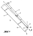
- the first axis is in Activity when the wing 2, starting from with the Frame 1 closed by a handle 5 Condition, swing opening. If a swing opening of about 90 ° is reached, the second oscillation axis occurs in function, which leaves the wing 2 further from the frame 1 takes off. After a swing opening movement of the Wing 2 of approx. 160 ° is wing 2 in the shown cleaning position, in which the outside 4 of the wing 2 directed against the frame 1 and thus from the lower roof interior 6 comfortably is accessible for cleaning purposes.
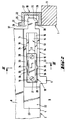
- a bolt housing 10 is located opposite the bolt 7, attached lying on the longitudinal leg 11 of the frame 1, at a short distance from the lower transverse leg 12 of the frame 1.
- the latch 7 has a flat rectangular circumference and is provided with a longitudinal recess 13 in the center.
- This longitudinal recess 13 comprises a receiving elongated hole 14, to which a guide slot 15 of smaller width adjoins to form edge strips 16 with sliding surfaces 17th
- the longitudinal recess 13 of the bolt 7 is of a T-shaped Enters guide piece 18, the crossbars 19th overlap the edge strips 16 and the receiving elongated hole Fill in 14 of the bar 7 flush.
- the side faces 20 of the longitudinal web 21 lie on the sliding surfaces 17th of the guide slot 15.
- the height of the longitudinal web 21 of the guide piece 18 is greater than the thickness of the edge strips 16, so that between the bottom 22 of the cutout 23 in the upper cross member 8 of the wing 2 and the floor 24 of the bolt 7 there is a game as in Fig. 3 shown the longitudinal displacement of the bolt 2 to facilitate.
- Lock housing 10 carries a lock opening 29, on the side adjacent to the frame 1 a web 30 is limited and the height between the Web 30 and the cover plate 32 is significantly larger than that Height of the locking tongue 25 together with the nose 26.
- the cover plate 32 carries an external, additional crossbar 31 in the plane of the web 30.
- Bolts 7 are notches 34 for working together with the locking cams 35 of the plastic Guide piece 18.
- the travel of the locking cams 35 is made possible by arranged in the area of the locking cams 36, the longitudinal slots 36 penetrating the transverse webs 19.
Landscapes
- Engineering & Computer Science (AREA)
- Mechanical Engineering (AREA)
- Architecture (AREA)
- Civil Engineering (AREA)
- Structural Engineering (AREA)
- Glass Compositions (AREA)
- Wing Frames And Configurations (AREA)
- Optical Head (AREA)
- Magnetic Heads (AREA)
- Window Of Vehicle (AREA)
- Liquid Crystal (AREA)
- Devices For Conveying Motion By Means Of Endless Flexible Members (AREA)
Description
- Fig. 1
- in schematischer Darstellung ein Dachfenster mit in Reinigungsstellung befindlichem Flügel,
- Fig. 2
- eine Ansicht in Pfeilrichtung aus Fig. 1 in vergrößertem Maßstab und
- Fig. 3
- einen Schnitt III-III durch Fig. 2, wiederum vergrößert.
Claims (7)
- Dachfenster mit einem Blendrahmen (1) und einem daran mittels eines insbesondere flügelhöhenmittig angeordneten Schwinglagers (3) angelenkten Flügel (2), der um eine Schwingachse so weit öffenbar ist, daß bei im Dach eingebautem Dachfenster die Außenseite (4) des Flügels (2) von der Raumseite (6) her zugänglich ist zu deren Reinigung und in dieser Reinigungsstellung der Flügel (2) gegen den Blendrahmen (1) mittels eines von Hand verschiebbaren Riegels (7) festlegbar ist, der sich am oberen, in Reinigungsstellung allerdings unten liegenden Querholm (8) befindet und mit einem am Längsschenkel (11) des Blendrahmens (1) nahe dessen unterem Querschenkel (12) angeordneten Schließgehäuses (10) zusammenwirkt, dadurch gekennzeichnet, daß die Schließzunge (25) des Riegels (7) mit einer Nase (26) versehen ist, die -unterstützt durch die aus dem Flügelgewicht resultierenden, die unten liegende obere Hälfte des Flügels (2) in Richtung des Rauminneren drängenden Reaktionskraft- einen die Schließöffnung (29) des Schließgehäuses (10) begrenzenden Steg (30) hintergreift, und daß die Höhe der Schließöffnung (29) größer ist als die Höhe der Schließzunge (25) im Bereich der Nase (26).
- Dachfenster nach Anspruch 1,
dadurch gekennzeichnet,
daß die Stirnseite (27) der Nase (26) mit einer Einführschräge (28) versehen ist. - Dachfenster nach mindestens einem der Ansprüche 1 und 2,
dadurch gekennzeichnet,
daß der flachrechteckige Riegel (7) mittig mit einer im Querschnitt abgesetzten Längsausnehmung (13) versehen ist unter Bildung eines Aufnahmelangloches (14) und eines von Randstreifen (16) begrenzten Führungslangloches (15), daß die Längsausnehmung (13) von einem T-förmigen Führungsstück (18) durchsetzt ist, dessen Querstege (19) die Randstreifen (16) übergreifen und im Aufnahmelangloch (14) angeordnet sind, während die Seitenflächen (20) des Längssteges (21) des Führungsstücks (18) zur Führung der Gleitflächen (17) des Führungslangloches (15) des Riegels (7) dienen und daß die Höhe des Längssteges (21) des Führungsstückes (18) größer ist als die Stärke der Randstreifen (16). - Dachfenster nach Anspruch 3,
dadurch gekennzeichnet,
daß der Riegel (7) mit dem Führungsstück (18) in mindestens den zwei Endschiebestellungen verrastbar ist. - Dachfenster nach Anspruch 4,
dadurch gekennzeichnet,
daß Rastkerben (34) in den Begrenzungswänden (33) des Aufnahmelangloches (14) angeordnet sind und das aus Kunststoff bestehende Führungsstück (18) im Bereich der zugeordneten Rastnocken (35) mit jeweils einem Längsschlitz (36) versehen ist. - Dachfenster nach mindestens einem der Ansprüche 1 bis 5,
dadurch gekennzeichnet,
daß der Riegel (7) flächenbündig in einer Ausfräsung (23) des Querholms (8) des Flügels (2) eingelassen angeordnet ist. - Dachfenster nach mindestens einem der Ansprüche 1 und 3,
dadurch gekennzeichnet,
daß das Schließgehäuse (10) mit einem zusätzlichen, außen liegenden Riegelsteg (31) versehen ist.
Applications Claiming Priority (2)
| Application Number | Priority Date | Filing Date | Title |
|---|---|---|---|
| DE9406933U DE9406933U1 (de) | 1994-04-26 | 1994-04-26 | Dachfenster |
| DE9406933U | 1994-04-26 |
Publications (2)
| Publication Number | Publication Date |
|---|---|
| EP0679777A1 EP0679777A1 (de) | 1995-11-02 |
| EP0679777B1 true EP0679777B1 (de) | 1999-08-04 |
Family
ID=6907864
Family Applications (1)
| Application Number | Title | Priority Date | Filing Date |
|---|---|---|---|
| EP95104541A Expired - Lifetime EP0679777B1 (de) | 1994-04-26 | 1995-03-28 | Dachfenster |
Country Status (4)
| Country | Link |
|---|---|
| EP (1) | EP0679777B1 (de) |
| AT (1) | ATE182946T1 (de) |
| DE (2) | DE9406933U1 (de) |
| DK (1) | DK0679777T3 (de) |
Family Cites Families (2)
| Publication number | Priority date | Publication date | Assignee | Title |
|---|---|---|---|---|
| DE2422570C3 (de) * | 1974-05-09 | 1982-04-15 | E.L. Hirz KG, 4130 Moers | Schrägdachfenster |
| DE8915013U1 (de) * | 1989-12-21 | 1990-03-22 | Mayer & Co., Salzburg | Halter, insbesondere für Flügel von Fenstern, Türen o.dgl. |
-
1994
- 1994-04-26 DE DE9406933U patent/DE9406933U1/de not_active Expired - Lifetime
-
1995
- 1995-03-28 EP EP95104541A patent/EP0679777B1/de not_active Expired - Lifetime
- 1995-03-28 DE DE59506503T patent/DE59506503D1/de not_active Expired - Lifetime
- 1995-03-28 DK DK95104541T patent/DK0679777T3/da active
- 1995-03-28 AT AT95104541T patent/ATE182946T1/de active
Also Published As
| Publication number | Publication date |
|---|---|
| ATE182946T1 (de) | 1999-08-15 |
| DK0679777T3 (da) | 2000-01-31 |
| EP0679777A1 (de) | 1995-11-02 |
| DE59506503D1 (de) | 1999-09-09 |
| DE9406933U1 (de) | 1994-08-04 |
Similar Documents
| Publication | Publication Date | Title |
|---|---|---|
| DE4239908C1 (de) | Drehfallenverschluß für Fahrzeuge, insbesondere zum Verriegeln einer Motorhaube von Kraftwagen | |
| EP0440987B2 (de) | Treibstangengetriebe | |
| EP0433623B1 (de) | Verriegelungsvorrichtung für ein Fenster, eine Tür od.dgl. | |
| EP0493689B1 (de) | Treibstangenbeschlag für Fenster, Türen od.dgl. | |
| DE8603031U1 (de) | Beschlag für einen wenigstens kippbaren Flügel eines Fensters, einer Tür od. dgl. | |
| EP1728956B1 (de) | Gegen ein Aushebeln von aussen sichernder Beschlag für eine Hebe-Schiebe-Tür | |
| CH653084A5 (en) | Locking device for sliding wings of windows or doors | |
| DE2658626B2 (de) | Schaltsperre für Treibstangenbeschläge | |
| EP0452890B1 (de) | Drehstangenverschluss | |
| EP0226698B1 (de) | Fehlbedienungssperre für Treibstangenbeschläge | |
| DE2209600A1 (de) | Winkelübertragungsglied für Fenster, Türen und dgl | |
| EP0572988A1 (de) | Schliessblech | |
| EP0679777A1 (de) | Dachfenster | |
| EP1231345B1 (de) | Gesteuerte Verriegelungsvorrichtung und Eckumlenkung | |
| AT390929B (de) | Verschlussvorrichtung zum loesbaren verbinden zweier teile eines lastfahrzeugaufbaues | |
| DE2745934A1 (de) | Ausstellvorrichtung fuer dreh-kipp- fluegel von fenstern, tueren o.dgl. | |
| DE3342661A1 (de) | Treibstangenbeschlag | |
| DE3008556C2 (de) | Kippriegel- und Verschlußvorrichtung für Drehkippflügel-Fenster und -Türen oder dgl. | |
| DE7901802U1 (de) | Schubriegel fuer fenster, tueren o.dgl. | |
| DE60201616T2 (de) | Feststeller für Tür, Fenster dgl. mit treibstangenverschlussartigen Beschlag | |
| EP0863282A2 (de) | Von Nutentiefen unabhängige Riegeleinrichtung für Flügel | |
| DE3215452A1 (de) | Eckumlenkung fuer treibstangenbeschlaege von fenstern, tueren od. dgl. | |
| EP0429981B1 (de) | Verdeckt im Falz angeordneter Beschlag für Kipp-Schwenk-flügelfenster oder -türen, insb. mit Holzrahmen | |
| DE8624314U1 (de) | Ausstellvorrichtung für den wenigstens drehbaren Flügel eines Fensters, einer Tür od.dgl. | |
| EP0280950B1 (de) | Beschlag für ein Fenster, eine Tür od. dgl. |
Legal Events
| Date | Code | Title | Description |
|---|---|---|---|
| PUAI | Public reference made under article 153(3) epc to a published international application that has entered the european phase |
Free format text: ORIGINAL CODE: 0009012 |
|
| AK | Designated contracting states |
Kind code of ref document: A1 Designated state(s): AT DE DK FR IT |
|
| 17P | Request for examination filed |
Effective date: 19960314 |
|
| 17Q | First examination report despatched |
Effective date: 19980513 |
|
| GRAG | Despatch of communication of intention to grant |
Free format text: ORIGINAL CODE: EPIDOS AGRA |
|
| GRAG | Despatch of communication of intention to grant |
Free format text: ORIGINAL CODE: EPIDOS AGRA |
|
| GRAH | Despatch of communication of intention to grant a patent |
Free format text: ORIGINAL CODE: EPIDOS IGRA |
|
| GRAH | Despatch of communication of intention to grant a patent |
Free format text: ORIGINAL CODE: EPIDOS IGRA |
|
| GRAA | (expected) grant |
Free format text: ORIGINAL CODE: 0009210 |
|
| AK | Designated contracting states |
Kind code of ref document: B1 Designated state(s): AT DE DK FR IT |
|
| REF | Corresponds to: |
Ref document number: 182946 Country of ref document: AT Date of ref document: 19990815 Kind code of ref document: T |
|
| REF | Corresponds to: |
Ref document number: 59506503 Country of ref document: DE Date of ref document: 19990909 |
|
| ET | Fr: translation filed | ||
| ITF | It: translation for a ep patent filed | ||
| REG | Reference to a national code |
Ref country code: DK Ref legal event code: T3 |
|
| PLBE | No opposition filed within time limit |
Free format text: ORIGINAL CODE: 0009261 |
|
| STAA | Information on the status of an ep patent application or granted ep patent |
Free format text: STATUS: NO OPPOSITION FILED WITHIN TIME LIMIT |
|
| 26N | No opposition filed | ||
| PGFP | Annual fee paid to national office [announced via postgrant information from national office to epo] |
Ref country code: DE Payment date: 20120220 Year of fee payment: 18 |
|
| PGFP | Annual fee paid to national office [announced via postgrant information from national office to epo] |
Ref country code: IT Payment date: 20120328 Year of fee payment: 18 |
|
| PGFP | Annual fee paid to national office [announced via postgrant information from national office to epo] |
Ref country code: FR Payment date: 20120416 Year of fee payment: 18 |
|
| PGFP | Annual fee paid to national office [announced via postgrant information from national office to epo] |
Ref country code: AT Payment date: 20120308 Year of fee payment: 18 |
|
| PGFP | Annual fee paid to national office [announced via postgrant information from national office to epo] |
Ref country code: DK Payment date: 20130307 Year of fee payment: 19 |
|
| REG | Reference to a national code |
Ref country code: AT Ref legal event code: MM01 Ref document number: 182946 Country of ref document: AT Kind code of ref document: T Effective date: 20130328 |
|
| REG | Reference to a national code |
Ref country code: FR Ref legal event code: ST Effective date: 20131129 |
|
| REG | Reference to a national code |
Ref country code: DE Ref legal event code: R119 Ref document number: 59506503 Country of ref document: DE Effective date: 20131001 |
|
| PG25 | Lapsed in a contracting state [announced via postgrant information from national office to epo] |
Ref country code: DE Free format text: LAPSE BECAUSE OF NON-PAYMENT OF DUE FEES Effective date: 20131001 Ref country code: FR Free format text: LAPSE BECAUSE OF NON-PAYMENT OF DUE FEES Effective date: 20130402 Ref country code: AT Free format text: LAPSE BECAUSE OF NON-PAYMENT OF DUE FEES Effective date: 20130328 |
|
| PG25 | Lapsed in a contracting state [announced via postgrant information from national office to epo] |
Ref country code: IT Free format text: LAPSE BECAUSE OF NON-PAYMENT OF DUE FEES Effective date: 20130328 |
|
| REG | Reference to a national code |
Ref country code: DK Ref legal event code: EBP Effective date: 20140331 |
|
| PG25 | Lapsed in a contracting state [announced via postgrant information from national office to epo] |
Ref country code: DK Free format text: LAPSE BECAUSE OF NON-PAYMENT OF DUE FEES Effective date: 20140331 |