EP0677780A2 - Verfahren zur Bearbeitung von Überlagerungsbildern - Google Patents
Verfahren zur Bearbeitung von Überlagerungsbildern Download PDFInfo
- Publication number
- EP0677780A2 EP0677780A2 EP95103748A EP95103748A EP0677780A2 EP 0677780 A2 EP0677780 A2 EP 0677780A2 EP 95103748 A EP95103748 A EP 95103748A EP 95103748 A EP95103748 A EP 95103748A EP 0677780 A2 EP0677780 A2 EP 0677780A2
- Authority
- EP
- European Patent Office
- Prior art keywords
- image
- radiation
- signal
- signals
- image signals
- Prior art date
- Legal status (The legal status is an assumption and is not a legal conclusion. Google has not performed a legal analysis and makes no representation as to the accuracy of the status listed.)
- Granted
Links
- 238000003672 processing method Methods 0.000 title claims description 217
- 230000005855 radiation Effects 0.000 claims abstract description 585
- 238000012545 processing Methods 0.000 claims description 311
- OAICVXFJPJFONN-UHFFFAOYSA-N Phosphorus Chemical compound [P] OAICVXFJPJFONN-UHFFFAOYSA-N 0.000 claims description 258
- 238000001914 filtration Methods 0.000 claims description 67
- 238000000034 method Methods 0.000 claims description 58
- 230000004044 response Effects 0.000 claims description 40
- 230000008569 process Effects 0.000 claims description 37
- 230000004936 stimulating effect Effects 0.000 claims description 28
- 238000009826 distribution Methods 0.000 claims description 19
- 206010073306 Exposure to radiation Diseases 0.000 claims description 10
- 238000007792 addition Methods 0.000 description 207
- 230000006870 function Effects 0.000 description 87
- 238000010586 diagram Methods 0.000 description 20
- 230000008859 change Effects 0.000 description 12
- 238000003745 diagnosis Methods 0.000 description 11
- QSIYTPCKNAPAJY-UHFFFAOYSA-N aluminum;ethoxy-oxido-oxophosphanium;2-(trichloromethylsulfanyl)isoindole-1,3-dione Chemical compound [Al+3].CCO[P+]([O-])=O.CCO[P+]([O-])=O.CCO[P+]([O-])=O.C1=CC=C2C(=O)N(SC(Cl)(Cl)Cl)C(=O)C2=C1 QSIYTPCKNAPAJY-UHFFFAOYSA-N 0.000 description 10
- 210000004072 lung Anatomy 0.000 description 8
- 238000001514 detection method Methods 0.000 description 7
- 230000004048 modification Effects 0.000 description 7
- 238000012986 modification Methods 0.000 description 7
- 101000920618 Homo sapiens Transcription and mRNA export factor ENY2 Proteins 0.000 description 6
- 102100031954 Transcription and mRNA export factor ENY2 Human genes 0.000 description 6
- 230000000694 effects Effects 0.000 description 5
- 101000798109 Homo sapiens Melanotransferrin Proteins 0.000 description 4
- 101000967073 Homo sapiens Metal regulatory transcription factor 1 Proteins 0.000 description 4
- 101001030197 Homo sapiens Myelin transcription factor 1 Proteins 0.000 description 4
- 102100040514 Metal regulatory transcription factor 1 Human genes 0.000 description 4
- 230000010355 oscillation Effects 0.000 description 4
- 101000967087 Homo sapiens Metal-response element-binding transcription factor 2 Proteins 0.000 description 3
- 102100040632 Metal-response element-binding transcription factor 2 Human genes 0.000 description 3
- 238000010521 absorption reaction Methods 0.000 description 3
- 230000002411 adverse Effects 0.000 description 3
- 238000004458 analytical method Methods 0.000 description 3
- 238000012546 transfer Methods 0.000 description 3
- 229910017435 S2 In Inorganic materials 0.000 description 2
- 230000008602 contraction Effects 0.000 description 2
- 229940039231 contrast media Drugs 0.000 description 2
- 239000002872 contrast media Substances 0.000 description 2
- 238000002347 injection Methods 0.000 description 2
- 239000007924 injection Substances 0.000 description 2
- 238000009877 rendering Methods 0.000 description 2
- NAWXUBYGYWOOIX-SFHVURJKSA-N (2s)-2-[[4-[2-(2,4-diaminoquinazolin-6-yl)ethyl]benzoyl]amino]-4-methylidenepentanedioic acid Chemical compound C1=CC2=NC(N)=NC(N)=C2C=C1CCC1=CC=C(C(=O)N[C@@H](CC(=C)C(O)=O)C(O)=O)C=C1 NAWXUBYGYWOOIX-SFHVURJKSA-N 0.000 description 1
- 229910052684 Cerium Inorganic materials 0.000 description 1
- RYGMFSIKBFXOCR-UHFFFAOYSA-N Copper Chemical compound [Cu] RYGMFSIKBFXOCR-UHFFFAOYSA-N 0.000 description 1
- NIXOWILDQLNWCW-UHFFFAOYSA-N acrylic acid group Chemical group C(C=C)(=O)O NIXOWILDQLNWCW-UHFFFAOYSA-N 0.000 description 1
- 230000008901 benefit Effects 0.000 description 1
- GWXLDORMOJMVQZ-UHFFFAOYSA-N cerium Chemical compound [Ce] GWXLDORMOJMVQZ-UHFFFAOYSA-N 0.000 description 1
- 238000006243 chemical reaction Methods 0.000 description 1
- 230000006835 compression Effects 0.000 description 1
- 238000007906 compression Methods 0.000 description 1
- 229910052802 copper Inorganic materials 0.000 description 1
- 239000010949 copper Substances 0.000 description 1
- 238000013461 design Methods 0.000 description 1
- 239000006185 dispersion Substances 0.000 description 1
- 239000000463 material Substances 0.000 description 1
- 238000005070 sampling Methods 0.000 description 1
- 230000035945 sensitivity Effects 0.000 description 1
- 239000000243 solution Substances 0.000 description 1
- 238000001228 spectrum Methods 0.000 description 1
- 230000000638 stimulation Effects 0.000 description 1
- 230000002123 temporal effect Effects 0.000 description 1
- 230000001131 transforming effect Effects 0.000 description 1
Images


Classifications
-
- G06T5/75—
-
- G—PHYSICS
- G06—COMPUTING; CALCULATING OR COUNTING
- G06T—IMAGE DATA PROCESSING OR GENERATION, IN GENERAL
- G06T5/00—Image enhancement or restoration
- G06T5/10—Image enhancement or restoration by non-spatial domain filtering
Definitions
- This invention relates to a superposition processing method for a radiation image, wherein an addition process is carried out on a plurality of image signals, which represent a radiation image of a single object or radiation images of the single object.
- This invention also relates to an energy subtraction processing method, wherein a subtraction process is carried out on a plurality of image signals representing radiation images of a single object.
- an X-ray image is recorded on an X-ray film having a small gamma value chosen according to the type of image processing to be carried out, the X-ray image is read out from the X-ray film and converted into an electric signal (i.e., an image signal), and the image signal is processed and then used for reproducing the X-ray image as a visible image on a photocopy, or the like.
- an electric signal i.e., an image signal
- stimulable phosphors in radiation image recording and reproducing systems. Specifically, a radiation image of an object, such as a human body, is recorded on a sheet provided with a layer of the stimulable phosphor (hereinafter referred to as a stimulable phosphor sheet).
- the stimulable phosphor sheet on which the radiation image has been stored, is then scanned with stimulating rays, such as a laser beam, which cause it to emit light in proportion to the amount of energy stored thereon during its exposure to the radiation.
- stimulating rays such as a laser beam
- Superposition processing is carried out in order to reduce the aforesaid noises markedly so that even small differences in the radiation energy absorption characteristics among structures of an object can be found accurately in a visible radiation image, which is reproduced finally, i.e. the detection performance of the radiation image can be improved markedly.
- Ordinary techniques and effects of the superposition processing are as described below.
- a radiation image is stored on each of a plurality of recording media, which have been placed one upon another. Thereafter, an image read-out operation is carried out for each of the recording media. A plurality of image signals, which have been obtained from the image read-out operations, are then superposed one upon another.
- noises described in (1) through (5) for the stimulable phosphor sheets exhibit different distributions for different radiation images stored on the stimulable phosphor sheets.
- the noises can be averaged. Therefore, the noises become imperceptible in a superposition image, which is obtained from superposition processing.
- an image signal having a high signal-to-noise ratio is obtained from superposition processing.
- S/N ratio signal-to-noise ratio
- the same effects can be obtained also when radiation images having been recorded on sheets of X-ray film are read out.
- most of the noises described in (1) through (5), particularly, the noise described in (1), which is one of dominant factors among the noises in a radiation image, can be approximated by the Poisson statistics.
- the level of the signal corresponding to a superposition image which is obtained by carrying out superposition processing on the two radiation images, becomes equal to S1+S2, and the level of noise in the superposition image is represented by Formula (1).
- the signal-to-noise ratios of the two radiation images prior to superposition processing are represented by the formulas S1/N1 and S2/N2.
- the signal-to-noise ratio of the resulting superposition image is represented by Formula (2). (S1 + S2)/ ⁇ N12 + N22 ⁇ Therefore, as a result of superposition processing, the signal-to-noise ratio can be improved.
- the values of the image signals may be weighted such that a markedly high signal-to-noise ratio can be obtained.
- two stimulable phosphor sheets have heretofore been housed in a cassette such that they overlap one upon the other. Radiation images of an object are then recorded on the two stimulable phosphor sheets housed in the cassette. Thereafter, an image read-out operation is carried out on each of the two stimulable phosphor sheets, and two image signals are thereby obtained.
- subtraction processing is carried out with either the so-called temporal (time difference) subtraction processing method or the so-called energy subtraction processing method.
- the image signal representing a radiation image obtained without injection of contrast media is subtracted from the image signal representing a radiation image in which the image of the specific structure of the object is enhanced by the injection of contrast media.
- an object is exposed to several kinds of radiation having different energy distributions.
- the energy distribution of the radiation carrying image information of an object is changed after it has been irradiated onto one of a plurality of radiation image recording media, after which the radiation impinges upon the second radiation image recording medium.
- the radiation image stored on the stimulable phosphor sheet is read out directly as an electric image signal. Therefore, with such radiation image recording and reproducing systems, the aforesaid subtraction processing can be carried out easily.
- radiation images may be stored on, for example, two stimulable phosphor sheets such that the parts of the radiation images corresponding to a specific structure may be different in the two radiation images.
- two-shot energy subtraction processing may be employed wherein the operation for recording a radiation image is carried out twice with two kinds of radiation having different energy distributions.
- one-shot energy subtraction processing may be employed wherein, for example, two stimulable phosphor sheets placed one upon the other (they may be in contact with each other or spaced away from each other) are simultaneously exposed to radiation, which has passed through an object, such that they may be exposed to radiation having different energy distributions.
- a method for photoelectrically detecting light emitted by a stimulable phosphor sheet As a method for photoelectrically detecting light emitted by a stimulable phosphor sheet, a method for detecting light emitted by two surfaces of a stimulable phosphor sheet has been proposed in, for example, U.S. Patent No. 4,346,295.
- two photoelectric read-out means are located on opposite sides of the stimulable phosphor sheet. The two surfaces or only one surface of the stimulable phosphor sheet is scanned with the stimulating rays, and the light emitted by the two surfaces of the stimulable phosphor sheet is photoelectrically detected by the two photoelectric read-out means.
- the proposed method for detecting light emitted by two surfaces of a stimulable phosphor sheet a single radiation image is stored on the stimulable phosphor sheet, and the light emitted by two surfaces of the stimulable phosphor sheet is detected on the two sides of the stimulable phosphor sheet. Therefore, the efficiency, with which the light emitted by the stimulable phosphor sheet is guided and detected, can be kept high, and a high signal-to-noise ratio can be obtained.
- the stimulable phosphor sheet is placed on a transparent holder, and two photoelectric read-out means are respectively located above and below the holder. Specifically, the light emitted from the front surface of the stimulable phosphor sheet is detected by the photoelectric read-out means, which is located above the holder. Also, the light emitted from the back surface of the stimulable phosphor sheet is detected by the photoelectric read-out means, which is located below the holder.
- the image signal which is obtained from a stimulable phosphor sheet located at the position remote from the radiation source, contains image information in the low frequency band as in the image signal, which is obtained from a stimulable phosphor sheet located at the position close to the radiation source.
- the frequency dependency in the high frequency band is lower than in the image signal, which is obtained from the stimulable phosphor sheet located at the position close to the radiation source.
- the image signal which is obtained from the stimulable phosphor sheet located at the position remote from the radiation source, as for the high frequency band
- the amount of image information becomes small, and the amount of the noise components due to the effects of scattered radiation, or the like, becomes large. Therefore, if the image signal, which is obtained from the stimulable phosphor sheet located at the position remote from the radiation source, and the image signal, which is obtained from the stimulable phosphor sheet located at the position close to the radiation source, are weighted in the same manner and added to each other, the image quality can be kept good in the low frequency band in the addition signal obtained from the addition process, but the noise components will be emphasized and adversely affect the image quality in the high frequency band.
- the response speed of a stimulable phosphor with respect to stimulating rays i.e. to increase the speed of light emission response of the stimulable phosphor with respect to the irradiation of the stimulating rays, with a method wherein, for example, cerium is added to the stimulable phosphor.
- cerium is added to the stimulable phosphor.
- the stimulating rays are moved very quickly on the stimulable phosphor sheet. Therefore, with certain kinds of stimulable phosphors constituting the stimulable phosphor sheets, the problems often occur in that the stimulable phosphor sheet cannot emit light immediately after being exposed to the stimulating rays, and a time lag occurs between when the stimulable phosphor sheet is exposed to the stimulating rays and when the stimulable phosphor sheet emits light.
- the amount of the light emitted by the stimulable phosphor sheet changes sharply. Therefore, the values of the image signal, which correspond to an image contour portion, or the like, should change sharply in the main scanning direction.
- the values of the obtained image signal which correspond to an image contour portion, or the like, will not change sharply in the main scanning direction.
- the visible image reproduced from the image signal becomes unsharp in the main scanning direction, and the sharpness of the reproduced image cannot be kept high.
- Noise contained in an image signal is also affected by the dose of radiation delivered to the stimulable phosphor sheet.
- the proportion of the fixed noise due to the structure of the stimulable phosphor sheet such as the state in which the stimulable phosphor is applied to the stimulable phosphor sheet, becomes higher than the proportion of the quantum noise of the radiation. Therefore, the ratio, in which a frequency band of the image signal is to be weighted such that the image quality of the reproduced image obtained from the addition signal or the subtraction signal may be kept best, varies for different doses of radiation delivered to the object.
- the primary object of the present invention is to provide a superposition processing method for a radiation image, wherein a superposition image having good image quality and containing little noise component is obtained.
- Another object of the present invention is to provide an energy subtraction processing method, wherein an energy subtraction image having good image quality and containing little noise component is obtained.
- a further object of the present invention is to provide a superposition processing method for a radiation image, wherein the addition process on image signals is carried out simply, at a low cost, quickly, and for each of different frequencies.
- a still further object of the present invention is to provide a superposition processing method for a radiation image, wherein a reproduced image having a high sharpness is obtained from image signals detected with operations for quickly reading out a radiation image.
- Another object of the present invention is to provide a superposition processing method for a radiation image, wherein the addition process on image signals is carried out simply, at a low cost, quickly, and for each of different frequencies, and wherein the components of a desired frequency band in an image signal are capable of being altered.
- a further object of the present invention is to provide an energy subtraction processing method, wherein the subtraction process on image signals is carried out simply, at a low cost, quickly, and for each of different frequencies, and wherein the components of a desired frequency band in an image signal are capable of being altered.
- a still further object of the present invention is to provide a superposition processing method for a radiation image, wherein a reproduced image having good image quality is obtained regardless of the dose of radiation delivered to an object, and wherein the addition process on image signals is carried out simply, at a low cost, quickly, and for each of different frequencies.
- Another object of the present invention is to provide an energy subtraction processing method, wherein a reproduced image having good image quality is obtained regardless of the dose of radiation delivered to an object, and wherein the subtraction process on image signals is carried out simply, at a low cost, quickly, and for each of different frequencies.
- the present invention provides a first superposition processing method for a radiation image, comprising the steps of:
- the present invention also provides a second superposition processing method for a radiation image, wherein the first superposition processing method for a radiation image in accordance with the present invention is modified such that the image superposition processing may be carried out by:
- the present invention further provides a third superposition processing method for a radiation image, wherein the first superposition processing method for a radiation image in accordance with the present invention is modified such that the image superposition processing may be carried out by:
- transform to multi-resolution space means a transform, such as a wavelet transform or a sub-band transform, wherein an image signal is decomposed into a plurality of signals of different frequency bands by using a filter, which is shorter than a filter employed in the Fourier transform.
- the wavelet transform has recently been developed as a frequency analysis method and has heretofore been applied to stereo pattern matching, signal compression, and the like.
- the wavelet transform is described in, for example, "Wavelets and Signal Processing,” by Olivier Rioul and Martin Vetterli, IEEE SP Magazine, pp. 14-38, October 1991; and "Zero-Crossings of a Wavelet Transform,” by Stephane Mallat, IEEE Transactions on Information Theory, Vol. 37, No. 4, pp. 1019-1033, July 1991.
- a signal is transformed into frequency signals, each being of one of a plurality of different frequency bands, by utilizing a function h, which is shown in Figure 22, as a basic function and in accordance with the formula wherein
- the present invention still further provides a fourth superposition processing method for a radiation image, wherein the third superposition processing method for a radiation image in accordance with the present invention is modified such that the transform to multi-resolution space may be carried out with a wavelet transform.
- the present invention also provides a fifth superposition processing method for a radiation image, wherein the first, third, or fourth superposition processing method for a radiation image in accordance with the present invention is modified such that the value of the weight factor with respect to a portion of the radiation image, to which a large dose of radiation reached during an operation for recording the radiation image, may be rendered larger than the value of the weight factor with respect to a portion of the radiation image, to which a small dose of radiation reached during the operation for recording the radiation image, in accordance with the portions of the object, the patterns of which are embedded in the radiation image.
- the present invention further provides a sixth superposition processing method for a radiation image, wherein the first, second, third, fourth, or fifth superposition processing method for a radiation image in accordance with the present invention is modified such that the plurality of the image signals are obtained by: exposing the two surfaces or either one of the two surfaces of a single stimulable phosphor sheet, on which the radiation image has been stored, to stimulating rays, which cause the stimulable phosphor sheet to emit light in proportion to the amount of energy stored thereon during its exposure to radiation, and photoelectrically detecting the emitted light independently on the opposite surface sides of the stimulable phosphor sheet.
- the present invention still further provides a seventh superposition processing method for a radiation image, wherein the first superposition processing method for a radiation image in accordance with the present invention is modified such that the plurality of the image signals may be analog image signals, and the image superposition processing may be carried out by:
- the present invention also provides an eighth superposition processing method for a radiation image, wherein the first superposition processing method for a radiation image in accordance with the present invention is modified such that the plurality of the image signals may be analog image signals, and the image superposition processing may be carried out by:
- the present invention further provides a ninth superposition processing method for a radiation image, wherein the first, second, third, fourth, fifth, seventh, or eighth superposition processing method for a radiation image in accordance with the present invention is modified such that the plurality of the image signals are obtained by: exposing each of at least two stimulable phosphor sheets, on each of which a radiation image has been stored, to stimulating rays, which cause the stimulable phosphor sheet to emit light in proportion to the amount of energy stored thereon during its exposure to radiation, and photoelectrically detecting the emitted light.
- the present invention still further provides a first energy subtraction processing method comprising the steps of:
- the expression of "with a plurality of kinds of radiation having different energy distributions” does not necessarily means a plurality of separate radiations but includes a plurality of kinds of radiations originated from a single radiation wherein, for example, one is a direct radiation from a radiation source, and the other is a radiation from the same radiation source, which has passed through a recording medium (e.g., a stimulable phosphor sheet) and/or a filter, or the like, and the low energy components of which have been filtered out. Therefore, the plurality of the radiation images can be formed one after another by using different radiations having different energy distributions.
- a recording medium e.g., a stimulable phosphor sheet
- the plurality of the radiation images can be formed simultaneously by using a single radiation and placing a plurality of recording media (e.g., stimulable phosphor sheets) one upon another with or without a filter interposed therebetween.
- a plurality of recording media e.g., stimulable phosphor sheets
- the stimulable phosphor sheet located closer to the radiation source serves as a filter for filtering out the low energy components of the radiation.
- the present invention also provides a second energy subtraction processing method, wherein the first energy subtraction processing method in accordance with the present invention is modified such that the difference signal may be obtained by:
- the present invention further provides a third energy subtraction processing method, wherein the first energy subtraction processing method in accordance with the present invention is modified such that the subtraction signal may be obtained by:
- the present invention still further provides a fourth energy subtraction processing method, wherein the third energy subtraction processing method in accordance with the present invention is modified such that the transform to multi-resolution space may be carried out with a wavelet transform.
- the present invention also provides a fifth energy subtraction processing method, wherein the first, third, or fourth energy subtraction processing method in accordance with the present invention is modified such that the value of the weight factor with respect to a portion of each radiation image, to which a large dose of radiation reached during an operation for recording the radiation image, may be rendered larger than the value of the weight factor with respect to a portion of the radiation image, to which a small dose of radiation reached during the operation for recording the radiation image, in accordance with the portions of the object, the patterns of which are embedded in the radiation image.
- the present invention further provides a sixth energy subtraction processing method, wherein the first energy subtraction processing method in accordance with the present invention is modified such that the plurality of the image signals may be analog image signals, and the difference signal may be obtained by:
- the present invention still further provides a seventh energy subtraction processing method, wherein the first energy subtraction processing method in accordance with the present invention is modified such that the plurality of the image signals may be analog image signals, and the difference signal may be obtained by:
- the value of the weight factor with respect to the frequency components, which have a low signal-to-noise ratio, is rendered smaller than the value of the weight factor with respect to the frequency components, which have a high signal-to-noise ratio, in accordance with the frequency characteristics of each of the image signals. Therefore, the addition signal, which is obtained from the addition process, has a high signal-to-noise ratio over the entire frequency bands. Accordingly, a superposition image having good image quality can be reproduced from the addition signal.
- the Fourier transform may be carried out on each of the image signals, and each of the image signals may thereby be decomposed into a plurality of Fourier transform factor signals, each being of one of different frequency bands.
- the weighted addition process may then be carried out on the Fourier transform factor signals, which are of a single frequency band, such that the values of the weight factors may be varied for the Fourier transform factor signals of the different frequency bands.
- the value of the weight factor with respect to the frequency components which have a low signal-to-noise ratio
- each of the image signals may be subjected to the transform to multi-resolution space, such as the wavelet transform or the sub-band transform, and may thereby be decomposed into a plurality of the transform factor signals, each being of one of different frequency bands.
- An addition signal may then be obtained from the transform factor signals.
- the image signal can be decomposed into the plurality of the frequency bands by using a short filter. Therefore, the apparatus for carrying out the superposition processing method for a radiation image in accordance with the present invention can be kept simple.
- the transform factor signals are obtained by transforming each of the image signals to multi-resolution space.
- Each of the transform factor signals thus obtained is constituted of an image signal contracted from the image signal before being transformed. Therefore, the dose of radiation, which reached to a portion of the radiation image during the operation for recording the radiation image, can be detected by carrying out, for example, an analysis of the probability density function of each of the transform factor signals. Thereafter, the value of the weight factor with respect to a portion of the radiation image, to which a large dose of radiation reached during the operation for recording the radiation image, can be rendered larger than the value of the weight factor with respect to a portion of the radiation image, to which a small dose of radiation reached during the operation for recording the radiation image. In this manner, an image having good image quality can be obtained.
- the plurality of the image signals may be taken as analog image signals.
- Filtering may be carried out on all of the analog image signals by using the filters, which have weights changing the frequency characteristics of the analog image signals. In this manner, the weighting process is effected on desired frequency bands of the analog image signals.
- filtering may be carried out on at least a single desired analog image signal, which is among the analog image signals, by using a filter, which has a weight changing the frequency characteristics of the desired analog image signal. In this manner, the weighting process is effected on a desired frequency band of the analog image signal.
- the addition signal may be obtained by carrying out the addition process on the image signals. In this manner, as in the aforesaid method utilizing the Fourier transform, the wavelet transform, or the sub-band transform, a superposition image having good image quality can be obtained from the addition signal.
- the high frequency components of the image signal which has been obtained from the back surface side of the stimulable phosphor sheet (i.e. the side of the stimulable phosphor sheet, which was remote from the radiation source during the operation for recording the radiation image), contain a large amount of noise components due to scattered radiation, or the like.
- the image signals are obtained by recording the radiation images respectively on a plurality of stimulable phosphor sheets placed one upon another
- the high frequency components of the image signal having been obtained from a stimulable phosphor sheet, which was remote from the radiation source during the operation for recording the radiation images contain a large amount of noise components due to scattered radiation, or the like.
- the value of the weight factor with respect to the high frequency components of the image signal which has been obtained from the side of the stimulable phosphor sheet remote from the radiation source or which has been obtained from the stimulable phosphor sheet remote from the radiation source, is rendered smaller than the value of the weight factor with respect to the high frequency components of the image signal, which has been obtained from the side of the stimulable phosphor sheet close to the radiation source or which has been obtained from the stimulable phosphor sheet close to the radiation source. In this manner, a superposition image containing little noise component can be obtained.
- the aforesaid process for varying the value of the weight factor for different frequency bands of the image signal can be applied to the energy subtraction processing method.
- the value of the weight factor with respect to the frequency components, which have a low signal-to-noise ratio is rendered smaller than the value of the weight factor with respect to the frequency components, which have a high signal-to-noise ratio, in accordance with the frequency characteristics of each of the image signals, which are to be subjected to the subtraction process.
- a subtraction signal which has been obtained from the subtraction process, contains little noise component, and a subtraction image having good image quality can be reproduced from the subtraction signal.
- the present invention also provides a tenth superposition processing method for a radiation image, comprising the steps of:
- the image processing may be carried out on all of the plurality of the image signals.
- the image processing may be the processing for carrying out the convolution of the desired image signal with a mask filter, which has predetermined frequency characteristics.
- the processing with the convolution may be carried out on all of the plurality of the image signals.
- the sum of the frequency characteristics of the mask filters employed for the plurality of the image signals may be equal to 1 at an arbitrary frequency.
- the tenth superposition processing method for a radiation image in accordance with the present invention should preferably be modified such that each of the plurality of the image signals may be obtained by scanning a stimulable phosphor sheet, on which the radiation image has been stored, with stimulating rays, which cause the stimulable phosphor sheet to emit light in proportion to the amount of energy stored thereon during its exposure to radiation, in the main scanning direction and the sub-scanning direction, the emitted light being detected photoelectrically, and the image processing is the processing for emphasizing the high frequency components of the desired image signal with respect to the main scanning direction.
- the processing should more preferably be the processing for carrying out the convolution of the desired image signal with respect to the main scanning direction with a mask filter, which has frequency characteristics capable of emphasizing the high frequency components of the desired image signal with respect to the main scanning direction.
- the image processing with the convolution may be carried out on each of the image signals by using a single mask filter.
- the present invention further provides an eleventh superposition processing method for a radiation image, comprising the steps of:
- the present invention still further provides an eighth energy subtraction processing method comprising the steps of:
- the image processing may be carried out on all of the plurality of the image signals.
- the image processing may be the processing for carrying out the convolution of the desired image signal with a mask filter, which has predetermined frequency characteristics.
- the processing with the convolution may be carried out on all of the plurality of the image signals.
- the tenth superposition processing method for a radiation image in accordance with the present invention at least a single desired image signal, which is among the plurality of the image signals, is subjected to the image processing, which changes the frequency characteristics of the desired image signal.
- the frequency characteristics of the desired image signal can be changed such that noise may be reduced. Therefore, the radiation image represented by the addition signal can have good image quality and little noise.
- the image processing, which changes the frequency characteristics of the image signal is carried out on the entire image signal. Therefore, it is not necessary to carry out a frequency transform, such as the wavelet transform or the Fourier transform.
- the amount of calculation can be kept small, and the apparatus for carrying out the superposition processing method for a radiation image in accordance with the present invention can be kept simple. As a result, a superposition image having good image quality can be obtained quickly and at a low cost.
- addition signals in which the responses with respect to various frequency bands have been emphasized, can be obtained by changing the frequency characteristics of the mask filter.
- the operation time can be kept short, and the addition process can be carried out quickly.
- the number of the mask filters, which are to be stored in an apparatus for carrying out the superposition processing method for a radiation image in accordance with the present invention can be kept small. Therefore, the apparatus can be kept simple.
- the difference signal between the two image signals is obtained.
- the convolution of the difference signal is carried out with either one of two mask filters, the sum of the frequency characteristics of the two mask filters being equal to 1 at an arbitrary frequency.
- the difference signal, which has been obtained from the convolution, and either one of the two image signals are then added to each other.
- each of the plurality of the image signals may be obtained by scanning a stimulable phosphor sheet, on which the radiation image has been stored, with stimulating rays, which cause the stimulable phosphor sheet to emit light in proportion to the amount of energy stored thereon during its exposure to radiation, in the main scanning direction and the sub-scanning direction, the emitted light being detected photoelectrically.
- the image processing may be the processing for carrying out the convolution of the desired image signal with respect to the main scanning direction with a mask filter, which has the frequency characteristics capable of emphasizing the high frequency components of the desired image signal with respect to the main scanning direction.
- the convolution of the desired image signal may be carried out with respect to the sub-scanning direction with a mask filter, which has predetermined frequency characteristics.
- a mask filter which has predetermined frequency characteristics.
- the high frequency components of the image signal with respect to the main scanning direction i.e. an image part, such as an contour part of the image, at which the values of the image signal change sharply, can be emphasized.
- the part, at which the value of the image signal should change sharply, but which has been rendered unsharp due to the quick image read-out operation can be emphasized.
- An image signal, in which the problems with regard to the unsharp change have been eliminated, can thus be obtained. Therefore, in cases where the image read-out operation is carried out quickly, the image signal can be prevented from becoming unsharp with respect to the main scanning direction, and a reproduced image having a high sharpness can be obtained.
- the processing carried out in the tenth or eleventh superposition processing method for a radiation image in accordance with the present invention can also be applied to the energy subtraction processing in the eighth energy subtraction processing method in accordance with the present invention. Therefore, with the eighth energy subtraction processing method in accordance with the present invention, a difference signal representing an image having good image quality and containing little noise can be obtained from the subtraction processing. Also, the image processing, which changes the frequency characteristics of the image signal, is carried out on the entire image signal. Therefore, it is not necessary to carry out a frequency transform, such as the wavelet transform or the Fourier transform. Accordingly, the amount of calculation can be kept small, and the apparatus for carrying out the eighth energy subtraction processing method in accordance with the present invention can be kept simple. As a result, a subtraction image having good image quality can be obtained quickly and at a low cost.
- the present invention still further provides a twelfth superposition processing method for a radiation image, comprising the steps of:
- the twelfth superposition processing method for a radiation image in accordance with the present invention should preferably be modified such that each of the plurality of the image signals may be obtained by scanning a sheet-like recording medium, on which the radiation image has been recorded, with a light beam in the main scanning direction and the sub-scanning direction, the radiation image being thereby read out photoelectrically, and the processed image signal may be obtained by carrying out the convolution of the desired image signal with the mask filter, which has different frequency characteristics with respect to the main scanning direction and the sub-scanning direction, such that the frequency response characteristics of the addition signal with respect to the main scanning direction and the frequency response characteristics of the addition signal with respect to the sub-scanning direction may become approximately identical with each other.
- the processing with the convolution may be carried out on all of the plurality of the image signals.
- the present invention also provides a ninth energy subtraction processing method comprising the steps of:
- the ninth energy subtraction processing method in accordance with the present invention should preferably be modified such that each of the plurality of the image signals may be obtained by scanning a sheet-like recording medium, on which the radiation image has been recorded, with a light beam in the main scanning direction and the sub-scanning direction, the radiation image being thereby read out photoelectrically, and the processed image signal may be obtained by carrying out the convolution of the desired image signal with the mask filter, which has different frequency characteristics with respect to the main scanning direction and the sub-scanning direction, such that the frequency response characteristics of the difference signal with respect to the main scanning direction and the frequency response characteristics of the difference signal with respect to the sub-scanning direction may become approximately identical with each other.
- the processing with the convolution may be carried out on all of the plurality of the image signals.
- the convolution of at least a single desired image signal is carried out with the mask filter, which has frequency characteristics capable of keeping the signal-to-noise ratio of the addition signal high and altering the response characteristics of the addition signal with respect to a desired frequency band.
- the processed image signal obtained from the convolution and the other image signals are then added to one another. Therefore, in the obtained addition signal, noise components can be reduced, and the response characteristics with respect to a desired frequency band can be altered. Accordingly, the radiation image represented by the addition signal can have good image quality and little noise. Further, in the radiation image, the desired frequency band has been altered.
- a superposition image can be obtained which has good image quality and can serve as an effective tool in, particularly, the efficient and accurate diagnosis of an illness.
- the processing with the convolution is carried out on the entire image signal. Therefore, it is not necessary to carry out a frequency transform, such as the wavelet transform or the Fourier transform. Also, it is not necessary to carry out filtering processing on the addition signal. Accordingly, the amount of calculation can be kept small, and the apparatus for carrying out the superposition processing method for a radiation image in accordance with the present invention can be kept simple. As a result, a superposition image having good image quality can be obtained quickly and at a low cost.
- each of the plurality of the image signals may be obtained by scanning the sheet-like recording medium, on which the radiation image has been recorded, with a light beam in two-dimensional directions.
- the processed image signal may then be obtained by carrying out the convolution of the desired image signal with the mask filter, which has different frequency characteristics with respect to the main scanning direction and the sub-scanning direction, such that the frequency response characteristics of the addition signal with respect to the main scanning direction and the frequency response characteristics of the addition signal with respect to the sub-scanning direction may become approximately identical with each other.
- the frequency characteristics with respect to the main scanning direction and the frequency characteristics with respect to the sub-scanning direction become well-balanced.
- a reproduced image can be obtained which has better image quality and can serve as a more effective tool in, particularly, the efficient and accurate diagnosis of an illness.
- the processing carried out in the twelfth superposition processing method for a radiation image in accordance with the present invention can also be applied to the energy subtraction processing in the ninth energy subtraction processing method in accordance with the present invention. Therefore, with the ninth energy subtraction processing method in accordance with the present invention, a difference signal representing an image having good image quality and containing little noise can be obtained from the subtraction processing, and the response characteristics with respect to a desired frequency band can be altered. Accordingly, the radiation image represented by the difference signal can have good image quality and little noise. Further, in the radiation image, the desired frequency band has been altered. As a result, a subtraction image can be obtained which has good image quality and can serve as an effective tool in, particularly, the efficient and accurate diagnosis of an illness.
- the processing with the convolution is carried out on the entire image signal. Therefore, it is not necessary to carry out a frequency transform, such as the wavelet transform or the Fourier transform. Also, it is not necessary to carry out filtering processing on the difference signal. Accordingly, the amount of calculation can be kept small, and the apparatus for carrying out the energy subtraction processing method in accordance with the present invention can be kept simple. As a result, a subtraction image having good image quality can be obtained quickly and at a low cost.
- a frequency transform such as the wavelet transform or the Fourier transform.
- filtering processing on the difference signal. Accordingly, the amount of calculation can be kept small, and the apparatus for carrying out the energy subtraction processing method in accordance with the present invention can be kept simple. As a result, a subtraction image having good image quality can be obtained quickly and at a low cost.
- the present invention further provides a thirteenth superposition processing method for a radiation image, comprising the steps of:
- the processing with the convolution may be carried out on all of the plurality of the image signals.
- the sum of the frequency characteristics of the mask filters employed for the plurality of the image signals may be equal to 1 at an arbitrary frequency.
- the thirteenth superposition processing method for a radiation image in accordance with the present invention may be modified such that the dose of radiation may be calculated for each of portions of the object, the patterns of which are embedded in the radiation image, the mask filter may be set for each of the portions of the object in accordance with the calculated dose of radiation, and the convolution of the desired image signal may be carried out with the mask filter, which has been set for each of the portions of the object.
- the image processing with the convolution may be carried out on each of the image signals by using a single mask filter.
- the present invention still further provides a tenth energy subtraction processing method comprising the steps of:
- the tenth energy subtraction processing method in accordance with the present invention may be modified such that the dose of radiation may be calculated for each of portions of the object, the patterns of which are embedded in the radiation image, the mask filter may be set for each of the portions of the object in accordance with the calculated dose of radiation, and the convolution of the desired image signal may be carried out with the mask filter, which has been set for each of the portions of the object.
- the processing with the convolution may be carried out on all of the plurality of the image signals.
- the sum of the frequency characteristics of the mask filters employed for the plurality of the image signals may be equal to 1 at an arbitrary frequency.
- the dose of radiation delivered to the object is calculated.
- the mask filter to be used for the convolution of at least a single desired image signal is set in accordance with the calculated dose of radiation. Therefore, the mask filter, which can yield the addition signal representing a radiation image having good image quality, can be set in accordance with the dose of radiation delivered to the object. As a result, a superposition image having good image quality can be obtained regardless of the dose of radiation delivered to the object.
- the processing for changing the frequency characteristics is carried out on the entire image signal.
- a frequency transform such as the wavelet transform or the Fourier transform. Accordingly, the amount of calculation can be kept small, and the apparatus for carrying out the superposition processing method for a radiation image in accordance with the present invention can be kept simple. As a result, a superposition image having good image quality can be obtained quickly and at a low cost.
- the sum of the frequency characteristics of the mask filters, which are employed for the plurality of the image signals is equal to 1 at an arbitrary frequency
- the weighting process it becomes unnecessary for the weighting process to be carried out such that the addition ratio of the image signals may be equal to 1. Therefore, the operation time can be kept short, and the addition process can be carried out quickly.
- the dose of radiation may be calculated for each of portions of the object, the patterns of which are embedded in the radiation image.
- the mask filter may then be set for each of the portions of the object in accordance with the calculated dose of radiation.
- the number of the mask filters, which are to be stored in an apparatus for carrying out the superposition processing method for a radiation image in accordance with the present invention can be kept small. Therefore, the apparatus can be kept simple.
- the processing carried out in the thirteenth superposition processing method for a radiation image in accordance with the present invention can also be applied to the energy subtraction processing in the tenth energy subtraction processing method in accordance with the present invention. Therefore, with the tenth energy subtraction processing method in accordance with the present invention, a difference signal representing an image having good image quality and containing little noise in accordance with the dose of radiation delivered to the object can be obtained from the subtraction processing. Also, the image processing, which changes the frequency characteristics of the image signal, is carried out on the entire image signal. Therefore, it is not necessary to carry out a frequency transform, such as the wavelet transform or the Fourier transform.
- the amount of calculation can be kept small, and the apparatus for carrying out the tenth energy subtraction processing method in accordance with the present invention can be kept simple. As a result, a subtraction image having good image quality can be obtained quickly and at a low cost.
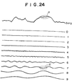
- Figure 1 shows how radiation 2, which has passed through a single object 1, is irradiated to two stimulable phosphor sheets 4A and 4B.
- the first stimulable phosphor sheet 4A and the second stimulable phosphor sheet 4B are superposed one upon the other, and a radiation source 3 is activated to produce the radiation 2.
- the radiation 2, which has been produced by the radiation source 3, passes through the object 1.
- the radiation 2, which has passed through the object 1, impinges upon the first stimulable phosphor sheet 4A and the second stimulable phosphor sheet 4B. In this manner, radiation images of the object 1 are stored on the first stimulable phosphor sheet 4A and the second stimulable phosphor sheet 4B.
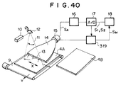
- the radiation images are read out from the first stimulable phosphor sheet 4A and the second stimulable phosphor sheet 4B by using an image read-out means shown in Figure 2, and image signals representing the radiation images are thereby obtained.
- the first stimulable phosphor sheet 4A is moved by a sub-scanning means 9 in the sub-scanning direction indicated by the arrow Y.
- the sub-scanning means 9 may be constituted of an endless belt, or the like.
- a laser beam 11, which serves as stimulating rays is produced by a laser beam source 10.
- the laser beam 11 is deflected by a scanning mirror 12 and caused to scan the stimulable phosphor sheet 4A in the main scanning directions indicated by the double-headed arrow X.
- the stimulable phosphor sheet 4A When the stimulable phosphor sheet 4A is exposed to the laser beam 11, it emits light 13 in proportion to the amount of energy stored thereon during its exposure to the radiation 2.
- the emitted light 13 enters a light guide member 14, which is made from a transparent acrylic plate, from its one edge face.
- the emitted light 13 is guided through repeated total reflection inside of the light guide member 14 and detected by a photomultiplier 15.
- the photomultiplier 15 generates an output signal SA corresponding to the amount of the emitted light 13, i.e. representing the radiation image stored on the stimulable phosphor sheet 4A.
- the output signal SA is logarithmically amplified by a logarithmic amplifier 16 and is then converted by an analog-to-digital converter 17 into a digital image signal S1.
- the digital image signal S1 is stored on a storage medium 18, such as a magnetic disk. Thereafter, the radiation image stored on the second stimulable phosphor sheet 4B is read out in the same manner as that described above, and an output signal SB representing the radiation image is thereby obtained.
- the output signal SB is logarithmically amplified by the logarithmic amplifier 16 and is then converted by the analog-to-digital converter 17 into a digital image signal S2.
- the digital image signal S2 is stored on the storage medium 18.
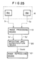
- FIG. 3 is a block diagram showing an apparatus for carrying out a first embodiment of the superposition processing method for a radiation image in accordance with the present invention.
- the image signals S1 and S2 are read from an image file 18A and an image file 18B in the storage medium 18 and fed into a wavelet transform means 19.
- the wavelet transform means 19 carries out a wavelet transform of each of the two image signals S1 and S2 and decomposes each of the two image signals S1 and S2 into a plurality of wavelet transform factor signals, each of which is of one of a plurality of different frequency bands. How the wavelet transform is carried out will be described hereinbelow.
- Figure 4 is a flow chart showing how the wavelet transform is carried out on each of the image signals S1 and S2. As an aid in facilitating the explanation, how the wavelet transform of the image signal S1 is carried out will be described hereinbelow.
- an orthogonal wavelet transform in which the respective wavelet transform factors are orthogonal, is carried out.
- the orthogonal wavelet transform is described in the aforesaid literature of Marc Antonini, et al.
- filtering processing is carried out with a function g and a function h, which are obtained from the basic wavelet function, on the image signal components of the image signal S1 representing picture elements in the radiation image, which are located along the main scanning direction.
- the filtering processing on the image signal components of the image signal S1 representing each row of the picture elements, which are arrayed along the main scanning direction is carried out with the function g and the function h each time the position of the filtering processing is shifted by a single picture element in the sub-scanning direction.
- wavelet transform factor signals Wg0 and Wh0 with respect to the main scanning direction of the image signal S1 are obtained.
- the function g and the function h can be uniquely obtained from the basic wavelet function.
- the function h has the characteristics shown in Table 1 below.
- a function h' is the one which is used when an inverse wavelet transform is carried out on an image signal having been subjected to the wavelet transform.
- the function g can be obtained from the function h', and a function g' to be used during the inverse wavelet transform can be obtained from the function h.
- Filtering processing is then carried out with the function g and the function h on the signal components of the thinned-out wavelet transform factor signals Wg0 and Wh0, which signal components represent picture elements located along the sub-scanning direction. From the filtering processing, wavelet transform factor signals WW U0 , WV U0 , VW U0 , and VV U0 are obtained.
- the signal components representing the picture elements located along the sub-scanning direction are thinned out alternately.
- the number of the picture elements located along the sub-scanning direction is reduced to 1/2.
- the number of the picture elements represented by each of the wavelet transform factor signals WW U0 , WV U0 , VW U0 , and VV U0 becomes equal to 1/4 of the number of the picture elements represented by the image signal S1.
- Filtering processing is then carried out with the function g and the function h on the signal components of the wavelet transform factor signal VV U0 , which represent picture elements located along the main scanning direction.
- the filtering processing on the image signal components of the wavelet transform factor signal VV U0 representing each row of the picture elements, which are arrayed along the main scanning direction is carried out with the function g and the function h each time the position of the filtering processing is shifted by a single picture element in the sub-scanning direction.
- wavelet transform factor signals Wg1 and Wh1 with respect to the main scanning direction of the wavelet transform factor signal VV U0 are obtained.
- the number of the picture elements represented by the wavelet transform factor signal VV U0 is equal to 1/2 of the number of the picture elements, which are represented by the original image signal, both in the main scanning direction and in the sub-scanning direction. Therefore, the resolution of the image represented by the wavelet transform factor signal VV U0 is equal to 1/2 of the resolution of the image represented by the original image signal. Accordingly, as a result of the filtering processing carried out with the function g and the function h on the wavelet transform factor signal VV U0 , the wavelet transform factor signals Wg1 and Wh1 representing the frequency components, which are lower than the frequency components represented by the wavelet transform factor signal VV U0 and which are among the frequency components of the original image signal, are obtained.
- the wavelet transform factor signals Wg1 and Wh1 are obtained in the manner described above. Thereafter, for each of the wavelet transform factor signals Wg1 and Wh1, the signal components representing the picture elements located along the main scanning direction are thinned out alternately. In this manner, the number of the picture elements located along the main scanning direction is reduced even further to 1/2. Filtering processing is then carried out with the function g and the function h on the signal components of the thinned-out wavelet transform factor signals Wg1 and Wh1, which signal components represent picture elements located along the sub-scanning direction. From the filtering processing, wavelet transform factor signals WW U1 , WV U1 , VW U1 , and VV U1 are obtained.
- the signal components representing the picture elements located along the sub-scanning direction are thinned out alternately.
- the number of the picture elements located along the sub-scanning direction is reduced to 1/2.
- the number of the picture elements represented by each of the wavelet transform factor signals WW U1 , WV U1 , VW U1 , and VV U1 becomes equal to 1/16 of the number of the picture elements represented by the image signal S1.
- filtering processing is carried out with the function g and the function h on the signal components of the thinned-out wavelet transform factor signal VV U1 , which represent picture elements located along the main scanning direction. Then, for each of the wavelet transform factor signals, which have thus been obtained, the signal components representing the picture elements located along the main scanning direction are thinned out alternately. Filtering processing is then carried out with the function g and the function h on the signal components of the thinned-out wavelet transform factor signals, which signal components represent picture elements located along the sub-scanning direction. From the filtering processing, wavelet transform factor signals WW U2 , WV U2 , VW U2 , and VV U2 are obtained.
- the wavelet transform described above is iterated N number of times, and wavelet transform factor signals WW U0 through WW UN , WV U0 through WV UN , VW U0 through VW UN , and VV UN are thereby obtained.
- the number of the picture elements represented by each of the wavelet transform factor signals WW UN , WV UN , VW UN , and VV UN which are obtained from the N'th wavelet transform, is equal to (1/2) N of the number of the picture elements, which are represented by the original image signal, both in the main scanning direction and in the sub-scanning direction. Therefore, as the value of N becomes larger, each wavelet transform factor signal is of a lower frequency band and represents lower frequency components among the frequency components of the original image signal.
- the wavelet transform factor signal WW Ui becomes a lower frequency signal.
- a wavelet transform factor signal WV Ui represents a change in the frequency of the image signal S1 in the main scanning direction.
- the wavelet transform factor signal WV Ui becomes a lower frequency signal.
- a wavelet transform factor signal VW Ui represents a change in the frequency of the image signal S1 in the sub-scanning direction.
- the wavelet transform factor signal VW Ui becomes a lower frequency signal.
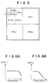
- Figure 5 shows images represented by the wavelet transform factor signals for the respective frequency bands.
- the wavelet transform factor signal WW U3 represents an image, which is obtained by reducing the original image to (1/2)3 in each of the main scanning direction and the sub-scanning direction.
- wavelet transforms are carried out on the image signal S2 in the same manner as that described above. From the wavelet transforms, wavelet transform factor signals WW L0 through WW LN , WV L0 through WV LN , VW L0 through VW LN , and VV LN are thereby obtained for the respective frequency bands.
- the wavelet transform factor signals which have thus been obtained by carrying out the wavelet transforms on the image signals S1 and S2, are fed into a weighting and superposition means 20.
- a weighting process is carried out such that the value of the weight factor with respect to the frequency band, which has a low signal-to-noise ratio, may be rendered smaller than the value of the weight factor with respect to the frequency band, which has a high signal-to-noise ratio. How the value of the weight factor is determined will be described below.
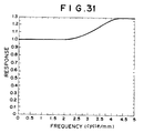
- the MTF can be obtained by recording a contrast transfer function chart (CTF chart) and represents the level of the resolution of the image signal with respect to each frequency band.
- CTF chart contrast transfer function chart
- the MTF1 of the image signal S1 which has been obtained from the stimulable phosphor sheet 4A located at the position closer to the radiation source during the image recording operation, takes a large value up to the high frequency band.
- the image signal S1 carries the information up to the high frequency band.
- the MTF2 of the image signal S2 which has been obtained from the stimulable phosphor sheet 4B located at the position remote from the radiation source during the image recording operation, takes a smaller value on the side of the high frequency band than the MTF1 of the image signal S1.
- the amount of information in the high frequency band is small. This indicates that the information in the high frequency band of the image signal S2 contains noise, due to scattered radiation during the image recording operation, or the like, and that the fine information on the high frequency band side has been rendered unsharp due to the location of the stimulable phosphor sheet 4B remote from the radiation source.
- the wavelet transform factor signals which are of a single frequency band, are weighted with the weight factors, such that the values of the weight factors may be varied in accordance with the MTF.
- the weighted wavelet transform factor signals, which are of a single frequency band, are then added to one another. How the values of the weight factors for the wavelet transform factor signals are determined will be described hereinbelow.
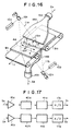
- the frequency characteristics MTF1 and MTF2 of the image signals shown in Figures 6A and 6B are calculated. Also, as illustrated in Figures 7A and 7B, frequency characteristics Winer 1 and Winer 2 of noise of the image signals are calculated.
- Each of the Winer 1 and the Winer 2 represents the amount of dispersion of the noise image signal, which has been obtained by recording an image of only the noise, i.e. by carrying out the image recording operation without the object lying, with respect to each frequency.
- the image of only the noise is recorded, and a noise image signal Image (X1) is obtained from the upper stimulable phosphor sheet 4A.
- a DQE index is defined by Formula (6).
- DQE ⁇ (MTF)2/Winer Formula (6) indicates that a higher DQE value represents better image quality.
- the DQE is calculated for each frequency.
- the image signals, Image 1 (X) and Image 2 (X), for each frequency band, which are obtained when the MTF1 and MTF2 are obtained, are added to each other, and an addition image signal add(t) is thereby obtained.
- the calculation is carried out with Formula (7).
- add(t) t ⁇ Image 1 (X) + (1-t) ⁇ Image 2 (X)
- the value of t is changed between 0 and 1, and a plurality of addition image signals add(t) are thereby obtained.
- the DQE is calculated for each of the addition image signals add(t) and plotted on the graph, in which the value of t is plotted on the horizontal axis, and the DQE is plotted on the vertical axis.
- Figures 8A, 8B, and 8C are graphs showing the relationship between t and DQE having been obtained for each of the plurality of frequency bands.
- the weight table shown in Figure 9 can be obtained.
- the wavelet transform factor signals, which are of a single frequency band, are weighted in accordance with the weight table shown in Figure 9, and the weighted wavelet transform factor signals, which are of a single frequency band, are then added to one another.
- the weighted additions of the wavelet transform factor signals are carried out with Formula (8)
- WW i t ⁇ WW Ui + (1 - t)
- VW Li t ⁇ VW Ui + (1 - t)
- VV i t ⁇ VV Ui + (1 - t) VV Li
- the wavelet transform factor signal WW L1 contains more noise and a smaller amount of information than the wavelet transform factor signal WW U1 . Therefore, when an addition wavelet transform factor signal WW1 for the high frequency band is to be obtained, the value of t is set to be large.
- the addition wavelet transform factor signal WW1 is calculated with Formula (9).
- WW1 0.8 ⁇ WW U1 + 0.2 ⁇ WW L1
- the weighting may be carried out in the same manner as that for the addition wavelet transform factor signal WW1.
- the differences in the amount of noise and the amount of information between the wavelet transform factor signals WW L2 and WW U2 are no so large as the differences between the wavelet transform factor signals WW L1 and WW U1 . Therefore, in cases where an addition wavelet transform factor signal WW2 for a frequency band lower than the frequency band of the addition wavelet transform factor signal WW1 is to be obtained, the value of t is set to be approximately 0.6.
- the addition wavelet transform factor signal WW2 is thus calculated with Formula (10).
- WW2 0.6 ⁇ WW U2 + 0.4 ⁇ WW L2
- the weighting may be carried out in the same manner as that for the addition wavelet transform factor signal WW2.
- the wavelet transform factor signals WW L3 and WW U3 represent approximately the same amounts of information. Therefore, in cases where an addition wavelet transform factor signal WW3 for a frequency band lower than the frequency band of the addition wavelet transform factor signal WW2 is to be obtained, the value of t is set to be 0.5.
- the weighting may be carried out in the same manner as that for the addition wavelet transform factor signal WW3.
- the wavelet transform factor signals WW L4 and WW U4 , the wavelet transform factor signals WW L5 and WW U5 , ..., the wavelet transform factor signals WW LN and WW UN respectively represent approximately the same amounts of information. Therefore, in cases where addition wavelet transform factor signals WW4, WW5, ..., WW N for frequency bands lower than the frequency band of the addition wavelet transform factor signal WW3 are to be obtained, the value of t is set to be 0.5.
- the values of the weight factors are determined in the manner described above. Therefore, regardless of the characteristics of the MTF and the Winer of the original image, appropriate values of the weight factors can be determined for each frequency.
- the addition wavelet transform factor signals WW1 through WW N , WV1 through WV N , VW1 through VW N , and VV1 through VV N are obtained in the weighting and superposition means 20. Thereafter, in an inverse wavelet transform means 21, an inverse wavelet transform is carried out on each of the addition wavelet transform factor signals. How the inverse wavelet transform is carried out will be described hereinbelow.
- Figure 10 is a flow chart showing how an inverse wavelet transform is carried out.
- each of the addition wavelet transform factor signals VV N , VW N , WV N , and WW N is subjected to the processing for leaving a space, which has a length equal to the length of a single picture element, between adjacent picture elements located along the sub-scanning direction.
- this processing is expressed as ⁇ 2.
- Filtering processing is then carried out with a function h', which is different from the aforesaid function h, on the signal components of the addition wavelet transform factor signal VV N provided with the spaces, which signal components represent picture elements located along the sub-scanning direction.
- filtering processing is carried out with a function g', which is different from the aforesaid function g, on the signal components of the addition wavelet transform factor signal VW N provided with the spaces, which signal components represent picture elements located along the sub-scanning direction.
- the filtering processing on the image signal components of the addition wavelet transform factor signal VV N representing each column of the picture elements, which are arrayed along the sub-scanning direction is carried out with the function h' each time the position of the filtering processing is shifted by a single picture element in the main scanning direction.
- the filtering processing on the image signal components of the addition wavelet transform factor signal VW N representing each column of the picture elements, which are arrayed along the sub-scanning direction is carried out with the function g' each time the position of the filtering processing is shifted by a single picture element in the main scanning direction.
- inverse wavelet transform factor signals are obtained from the addition wavelet transform factor signals VV N and VW N .
- the inverse wavelet transform factor signals are then doubled and added to each other. In this manner, an inverse wavelet transform factor signal WhN' is obtained.
- the function for the wavelet transform and the function for the inverse wavelet transform are different from each other. Specifically, it is difficult to design functions, which become identical in the wavelet transform and the inverse wavelet transform, i.e. which are the orthogonal functions. Therefore, it is necessary to relieve the conditions of orthogonality, continuity, shortness of function, or symmetry. Accordingly, in this embodiment, the conditions of orthogonality are relieved, and the functions satisfying the other conditions are thereby selected.
- the functions h and g for the wavelet transform and the functions h' and g' for the inverse wavelet transform are biorthogonal different functions. Therefore, the addition signal of the image signals S1 and S2 can be perfectly restored by subjecting the addition wavelet transform factor signals VV i , VW i , WV i , and WW i to the inverse wavelet transform with the functions h' and g'.
- filtering processing is carried out with the function h' on the signal components of the addition wavelet transform factor signal WV N , which represent picture elements located along the sub-scanning direction. Also, filtering processing is carried out with the function g' on the signal components of the addition wavelet transform factor signal WW N , which represent picture elements located along the sub-scanning direction.
- inverse wavelet transform factor signals are obtained from the addition wavelet transform factor signals WV N and WW N .
- the inverse wavelet transform factor signals are then doubled and added to each other. In this manner, an inverse wavelet transform factor signal WgN' is obtained.
- each of the inverse wavelet transform factor signals WhN' and WgN' is subjected to the processing for leaving a space, which has a length equal to the length of a single picture element, between adjacent picture elements located along the main scanning direction.
- Filtering processing is then carried out with the function h' on the signal components of the inverse wavelet transform factor signal WhN', which represent picture elements located along the main scanning direction.
- filtering processing is carried out with the function g' on the signal components of the inverse wavelet transform factor signal WgN', which represent picture elements located along the main scanning direction.
- inverse wavelet transform factor signals are obtained from the inverse wavelet transform factor signals WhN' and WgN'.
- the inverse wavelet transform factor signals, which have thus been obtained, are then doubled and added to each other. In this manner, an addition inverse wavelet transform factor signal VV N-1 ' is obtained.
- each of the addition inverse wavelet transform factor signal VV N-1 ' and the addition wavelet transform factor signals VW N-1 , WV N-1 , and WW N-1 is subjected to the processing for leaving a space, which has a length equal to the length of a single picture element, between adjacent picture elements located along the sub-scanning direction.
- Filtering processing is then carried out with the function h' on the signal components of the addition inverse wavelet transform factor signal VV N-1 ', which represent picture elements located along the sub-scanning direction.
- filtering processing is carried out with the function g' on the signal components of the addition wavelet transform factor signal VW N-1 , which represent picture elements located along the sub-scanning direction.
- the filtering processing on the image signal components of the addition inverse wavelet transform factor signal VV N-1 ' representing each column of the picture elements, which are arrayed along the sub-scanning direction is carried out with the function h' each time the position of the filtering processing is shifted by a single picture element in the main scanning direction. Also, the filtering processing on the image signal components of the addition wavelet transform factor signal VW N-1 representing each column of the picture elements, which are arrayed along the sub-scanning direction, is carried out with the function g' each time the position of the filtering processing is shifted by a single picture element in the main scanning direction.
- inverse wavelet transform factor signals are obtained from the addition inverse wavelet transform factor signal VV N-1 ' and the addition wavelet transform factor signal VW N-1 .
- the inverse wavelet transform factor signals, which have been obtained in this manner, are then doubled and added to each other. In this manner, an inverse wavelet transform factor signal WhN-1' is obtained.
- filtering processing is carried out with the function h' on the signal components of the addition wavelet transform factor signal WV N-1 , which represent picture elements located along the sub-scanning direction. Also, filtering processing is carried out with the function g' on the signal components of the addition wavelet transform factor signal WW N-1 , which represent picture elements located along the sub-scanning direction.
- inverse wavelet transform factor signals are obtained from the addition wavelet transform factor signals WV N-1 and WW N-1 .
- the inverse wavelet transform factor signals which have been obtained in this manner, are then doubled and added to each other. In this manner, an inverse wavelet transform factor signal WgN-1' is obtained.
- each of the inverse wavelet transform factor signals WhN-1' and WgN-1' is subjected to the processing for leaving a space, which has a length equal to the length of a single picture element, between adjacent picture elements located along the main scanning direction.
- Filtering processing is then carried out with the function h' on the signal components of the inverse wavelet transform factor signal WhN-1', which represent picture elements located along the main scanning direction.
- filtering processing is carried out with the function g' on the signal components of the inverse wavelet transform factor signal WgN-1', which represent picture elements located along the main scanning direction.
- inverse wavelet transform factor signals are obtained from the inverse wavelet transform factor signals WhN-1' and WgN-1'.
- the inverse wavelet transform factor signals, which have been obtained in this manner are then doubled and added to each other. In this manner, an addition inverse wavelet transform factor signal VV N-2 ' is obtained.
- the finally obtained addition inverse wavelet transform factor signal VV ⁇ 1' serves as an addition image signal Sadd of the image signals S1 and S2.
- the addition inverse wavelet transform factor signal VV ⁇ 1' which has thus been obtained, is subjected to predetermined image processing in an image processing means 22, fed into an image reproducing means 23, and used for the reproduction of a visible radiation image.
- the image reproducing means may be a display device, such as a cathode ray tube (CRT) display device, or a recording apparatus for recording an image on photosensitive film by scanning the photosensitive film with a light beam.
- a display device such as a cathode ray tube (CRT) display device
- a recording apparatus for recording an image on photosensitive film by scanning the photosensitive film with a light beam.
- the wavelet transform is carried out on each of the two image signals S1 and S2, and each of the two image signals S1 and S2 is thereby decomposed into a plurality of the wavelet transform factor signals, each of which is of one of a plurality of different frequency bands.
- the wavelet transform factor signals which are of a single frequency band, are weighted with the weight factors, such that the values of the weight factors may be varied for the wavelet transform factor signals of the different frequency bands.
- the value of the weight factor with respect to the image signal, which has been obtained from the stimulable phosphor sheet located at the position closer to the radiation source is set to be larger than the value of the weight factor with respect to the image signal, which has been obtained from the stimulable phosphor sheet located at the position remote from the radiation source.
- an addition wavelet transform factor signal in which the noise components contained in the image signal obtained from the stimulable phosphor sheet located at the position remote from the radiation source have been reduced.
- Each of the addition wavelet transform factor signals, which have thus been obtained is subjected to the inverse wavelet transform, and an addition signal is thereby obtained. From the addition signal thus obtained, an image having good image quality and containing little noise component can be reproduced.
- the functions having the characteristics shown in Table 1 are employed as the functions h and h' for the wavelet transform.
- the functions having the characteristics shown in Table 2 or Table 3 may be employed as the functions h and h' for the wavelet transform.
- any of other functions which can carry out the wavelet transform, may be employed.
- functions which are not biorthogonal nor symmetric, but which are orthogonal, may be employed.
- each of the two image signals S1 and S2 is decomposed by the wavelet transform into a plurality of the wavelet transform factor signals, each of which is of one of a plurality of different frequency bands.
- each of the two image signals S1 and S2 may be decomposed by a sub-band transform into a plurality of the transform factor signals, each of which is of one of a plurality of different frequency bands.
- the filtering processing of the image signal is carried out with a plurality of functions having different periods, and the plurality of the transform factor signals, each of which is of one of a plurality of different frequency bands, are thereby obtained with a single, simultaneous process.
- the filtering processing of the image signal is carried out with the function g and the function h, and the image signals for the plurality of the frequency bands are thereby obtained.
- the filtering processing of the image signal S1 is carried out with a plurality of functions g1, h1, g2, h2, ..., gN, hN such that the periods of the function g and the function h become two times, four times, ..., 2 n times.
- transform factor signals WW U1 , through WW UN , WV U1 through WV UN , VW U1 through VW UN , and VV U1 through VV UN are obtained for the plurality of frequency bands.
- transform factor signals WW L1 through WW LN , WV L1 through WV LN , VW L1 through VW LN , and VV L1 through VV LN are obtained for the plurality of frequency bands.
- the transform factor signals which are of a single frequency band, are weighted with the weight factors, such that the values of the weight factors may be varied for the transform factor signals of the different frequency bands.
- the weighted transform factor signals, which are of a single frequency band, are then added to one another, and an addition transform factor signal is thereby obtained for each of the different frequency bands.
- An inverse sub-band transform is then carried out on the addition transform factor signal. In this manner, as in the wavelet transform, an addition signal Sadd can be obtained from the weighted addition.
- the image signal is transformed into a plurality of image signals, each of which is of one of a plurality of different frequency bands.
- the image signal may be transformed into a plurality of image signals, each of which is of one of a plurality of different frequency bands, by carrying out a Fourier transform.
- long filters for different frequency bands must be employed in the Fourier transform. Therefore, even if a fast Fourier transform process is employed, the apparatus for carrying out the superposition processing method for a radiation image in accordance with the present invention will become comparatively complicated.
- the apparatus for carrying out the superposition processing method for a radiation image in accordance with the present invention can be kept simple.
- the frequency dependency characteristics of the image will also vary for different doses of radiation delivered to the stimulable phosphor sheet. Therefore, the middle dose of radiation may be detected from the image read-out apparatus during the image read-out operation. Reference may be made to addition ratio tables for different doses of radiation, and the addition ratio between the image signals may be determined for each of different frequency bands.
- the transform factor signals which have been obtained from the wavelet transform or the sub-band transform described above, constitute the image signals contracted from the original image signal.
- the transform factor signals obtained from the wavelet transform or the sub-band transform of the image signal represent the images contracted from the original image.
- the portions, which are to be used and therefore are required to have an appropriate image density in the reproduced image are the lung field patterns.
- lung field patterns 30, 30 are shown in the image represented by the transform factor signal WW U1 .
- the frequency dependency characteristics of the image vary for different doses of radiation delivered to the stimulable phosphor sheet. Therefore, the dose of radiation, which reached to each of portions of the radiation image during the operation for recording the radiation image, can be detected by carrying out, for example, an analysis of the probability density function of each of the transform factor signals, which have been obtained from the wavelet transform or the sub-band transform. Thereafter, the value of the weight factor with respect to the signal components of each transform factor signal representing a portion of the radiation image, to which a large dose of radiation reached during the operation for recording the radiation image, can be rendered larger than the value of the weight factor with respect to the signal components of each transform factor signal representing a portion of the radiation image, to which a small dose of radiation reached during the operation for recording the radiation image. In this manner, an image can be obtained which has good image quality and can serve as an effective tool in, particularly, the efficient and accurate diagnosis of an illness.
- the dose of radiation is calculated for each of the signal components of each transform factor signal.
- the signal components of each transform factor signal representing the picture elements in the lung field patterns to which a large dose of radiation reached, the value of the weight factor is set to be large.
- the superposition ratio of the signal components of the transform factor signal WW U1 , which represent the lung field patterns 30, 30, to the signal components of the transform factor signal WW L1 , which represent the lung field patterns 30, 30, is set to be 2:1.
- the superposition ratio of the signal components of the transform factor signal WW U1 , which represent a portion 31 other than the lung field patterns 30, 30, to the signal components of the transform factor signal WW L1 , which represent the portion 31, is set to be 1:1.
- the value of the weight factor with respect to the lung field patterns 30, 30, which are to be used and therefore are required to have an appropriate image density in the reproduced image, and to which a large dose of radiation reached during the operation for recording the radiation image, may be weighted even further, and the addition of the transform factor signals may thereby be carried out.
- the value of the weight factor during the addition may also be changed in accordance with the portions of the image.
- an addition signal can be obtained such that the value of the weight factor may be varied for different doses of radiation, which reached to portions of the radiation image during the operation for recording the radiation image. Therefore, an image can be obtained which has better image quality and can serve as a more effective tool in, particularly, the efficient and accurate diagnosis of an illness.
- the radiation images are recorded on the two stimulable phosphor sheets 4A and 4B.
- the image signals obtained from the two stimulable phosphor sheets 4A and 4B are then added to each other.
- the radiation image of the object 1 may be recorded on the single stimulable phosphor sheet 4A.
- two image signals to be added to each other may be obtained by detecting light emitted by the two surfaces of the stimulable phosphor sheet 4A. How the operation for detecting the light emitted by the two surfaces of the stimulable phosphor sheet 4A is carried out will be described hereinbelow.
- the stimulable phosphor sheet 4A is placed on endless belts 9a and 9b.
- the endless belts 9a and 9b are rotated by motors (not shown).
- a laser beam source 10 and a scanning mirror 12 are located above the stimulable phosphor sheet 4A.
- the laser beam source 10 produces a laser beam 11 serving as stimulating rays, which cause the stimulable phosphor sheet 4A to emit light in proportion to the amount of energy stored thereon during its exposure to the radiation.
- the scanning mirror 12 reflects and deflects the laser beam 11, which has been produced by the laser beam source 10, such that the laser beam 11 may scan the stimulable phosphor sheet 4A in main scanning directions.
- a light guide member 14a is located above and close to the position on the stimulable phosphor sheet 4A, which is being scanned with the laser beam 11.
- the light guide member 14a collects light, which is emitted by the stimulable phosphor sheet 4A when it is scanned with the laser beam 11, from above the stimulable phosphor sheet 4A.
- a light guide member 14b is located below the position on the stimulable phosphor sheet 4A, which is being scanned with the laser beam 11.
- the light guide member 14b is located perpendicularly to the stimulable phosphor sheet 4A and collects the light, which is emitted by the stimulable phosphor sheet 4A when it is scanned with the laser beam 11, from below the stimulable phosphor sheet 4A.
- the light guide members 14a and 14b are located such that they may respectively be in close contact with photomultipliers 15a and 15b, which photoelectrically detects the light emitted by the stimulable phosphor sheet 4A.
- the photomultipliers 15a and 15b are respectively connected to logarithmic amplifiers 16a and 16b.
- the logarithmic amplifiers 16a and 16b are respectively connected to analog-to-digital converters 17a and 17b.
- the analog-to-digital converters 17a and 17b are connected to a memory 18.
- the stimulable phosphor sheet 4A on which the radiation image has been stored, is set at a predetermined position on the endless belts 9a and 9b.
- the stimulable phosphor sheet 4A which has been set at the predetermined position, is conveyed by the endless belts 9a and 9b in a sub-scanning direction indicated by the arrow Y.
- the laser beam 11 is produced by the laser beam source 10.
- the laser beam 11, which has been produced by the laser beam source 10 is reflected and deflected by the scanning mirror 12.
- the laser beam 11, which has thus been reflected and deflected by the scanning mirror 12, impinges upon the stimulable phosphor sheet 4A and scans it in the main scanning directions indicated by the double headed arrow X.
- the main scanning directions are approximately normal to the sub-scanning direction indicated by the arrow Y.
- the exposed portion of the stimulable phosphor sheet 4A emits light in proportion to the amount of energy stored thereon during its exposure to the radiation.
- the light, which is emitted upwardly by the stimulable phosphor sheet 4A is represented by reference numeral 13a.
- the light, which is emitted downwardly by the stimulable phosphor sheet 4A, is represented by reference numeral 13b.
- the emitted light 13a is guided by the light guide member 14a and photoelectrically detected by the photomultiplier 15a.
- the emitted light 13a which has entered from the input end face of the light guide member 14a into the light guide member 14a, is guided through repeated total reflection inside of the light guide member 14a, emanates from the output end face of the light guide member 14a, and is received by the photomultiplier 15a.
- the amount of the emitted light 13a representing the radiation image is converted by the photomultiplier 15a into an electric signal.
- the emitted light 13b is guided by the light guide member 14b and is photoelectrically detected by the photomultiplier 15b.
- the photomultiplier 15a generates an analog output signal SA.
- the analog output signal SA is logarithmically amplified by the logarithmic amplifier 16a and converted into a digital image signal S1 by the analog-to-digital converter 17a.
- the digital image signal S1 is then fed into the memory 18.
- the photomultiplier 15b generates an analog output signal SB.
- the analog output signal SB is logarithmically amplified by the logarithmic amplifier 16b and converted into a digital image signal S2 by the analog-to-digital converter 17b.
- the digital image signal S2 is then fed into the memory 18.
- Each of the two image signals S1 and S2 is subjected to the wavelet transform or the sub-band transform and is thereby decomposed into a plurality of the transform factor signals, each of which is of one of a plurality of different frequency bands. Thereafter, in the same manner as that in the aforesaid embodiment, the transform factor signals, which are of a single frequency band, are weighted with the weight factors and added to each other.
- the transform factor signals for the high frequency band the value of the weight factor with respect to the image signal S1, which has been obtained from the front surface side of the stimulable phosphor sheet 4A (i.e.
- the side of the stimulable phosphor sheet 4A, which was closer to the radiation source during the operation for recording the radiation image is set to be larger than the value of the weight factor with respect to the image signal S2, which has been obtained from the back surface side of the stimulable phosphor sheet 4A (i.e. the side of the stimulable phosphor sheet 4A, which was remote from the radiation source during the operation for recording the radiation image).
- the addition transform factor signal, which has thus been obtained is then subjected to the inverse wavelet transform, the inverse sub-band transform, or the inverse Fourier transform. As in the aforesaid embodiment, an image having good image quality and containing little noise component can be reproduced from the addition signal, which has thus been obtained.
- the stimulable phosphor sheet 4A is scanned with the laser beam 11, which has been produced by the single laser beam source 10.
- a laser beam source 10a and a scanning mirror 12a may be located on the front surface side of the stimulable phosphor sheet 4A.
- a laser beam source 10b and a scanning mirror 12b may be located on the back surface side of the stimulable phosphor sheet 4A.
- the two surfaces of the stimulable phosphor sheet 4A may be scanned respectively with laser beams 11a and 11b, which have been produced by the laser beam sources 10a and 10b.
- the light emitted by the two surfaces of the stimulable phosphor sheet 4A may thus be detected, and two image signals may thereby be obtained.
- the value of the weight factor during the addition may be changed in accordance with the portions of the image.
- an addition signal can be obtained such that the value of the weight factor may be varied for different doses of radiation, which reached to different portions of the radiation image during the operation for recording the radiation image. Therefore, an image can be obtained which has better image quality and can serve as a more effective tool in, particularly, the efficient and accurate diagnosis of an illness.
- the processing for rendering the value of the weight factor with respect to the frequency components, which have a low signal-to-noise ratio, smaller than the value of the weight factor with respect to the frequency components, which have a high signal-to-noise ratio, in accordance with the frequency characteristics of each of the image signals S1 and S2 is carried out with the wavelet transform or the Fourier transform on the image signals S1 and S2 having been digitized by the analog-to-digital converter 17 or the analog-to-digital converters 17a and 17b.
- the processing described above may be carried out on the analog output signals SA and SB, which have been obtained from the stimulable phosphor sheets 4A and 4B in the radiation image read-out apparatus shown in Figure 2, or which have been obtained from the stimulable phosphor sheet 4A in the radiation image read-out apparatus shown in Figure 15 or Figure 16.
- FIG 17 is a block diagram showing how the processing is carried out on the analog output signals SA and SB.
- the analog output signals SA and SB are obtained from the stimulable phosphor sheets 4A and 4B in the radiation image read-out apparatus shown in Figure 2, or are obtained from the stimulable phosphor sheet 4A in the radiation image read-out apparatus shown in Figure 15 or Figure 16.
- the analog output signals SA and SB are respectively fed into logarithmic amplifiers 16a and 16b.
- the analog output signals SA and SB which have been logarithmically amplified by the logarithmic amplifiers 16a and 16b, are respectively fed into frequency processing circuits 40a and 40b. In the frequency processing circuits 40a and 40b, the processing described below is carried out.
- the high frequency components of the image signal which has been obtained from the back surface side of the stimulable phosphor sheet (i.e. the side of the stimulable phosphor sheet, which was remote from the radiation source during the operation for recording the radiation image), contain a large amount of noise components due to scattered radiation, or the like.
- the image signals are obtained by recording the radiation images respectively on a plurality of stimulable phosphor sheets placed one upon another
- the high frequency components of the image signal having been obtained from a stimulable phosphor sheet, which was remote from the radiation source during the operation for recording the radiation images contain a large amount of noise components due to scattered radiation, or the like.
- the value of the weight factor with respect to the high frequency components of the image signal which has been obtained from the side of the stimulable phosphor sheet remote from the radiation source or which has been obtained from the stimulable phosphor sheet remote from the radiation source, is rendered smaller than the value of the weight factor with respect to the high frequency components of the image signal, which has been obtained from the side of the stimulable phosphor sheet close to the radiation source or which has been obtained from the stimulable phosphor sheet close to the radiation source.
- the filtering processing for emphasizing the high frequency components of the output signal SA is carried out with a filter, which is shown in Figure 18.
- the filtering processing for reducing the high frequency components of the output signal SB is carried out with a filter, which is shown in Figure 19. Because the output signals SA and SB are the analog signals, the filtering processing described above is carried out only on the signal components of each of the output signals SA and SB with respect to the main scanning direction.
- the output signals SA and SB which have been subjected to the frequency processing in the frequency processing circuits 40a and 40b, are respectively fed into aliasing eliminating filters 41a and 41b.
- aliasing eliminating filters 41a and 41b errors due to aliasing are removed from the output signals SA and SB.
- the output signals SA and SB are fed into analog-to-digital converters 17a and 17b and converted into digital image signals S1 and S2.
- the digital image signals S1 and S2, which have thus been obtained, are added to each other.
- predetermined image processing is carried on the addition signal Sadd in the image processing means.
- the addition signal Sadd which has been obtained from the image processing, is then used for reproducing a visible image in the image reproducing means.
- the response of the means, such as the frequency processing circuit 40b and the aliasing eliminating filter 41b, for carrying out the filtering processing on the output signal SB, with respect to the high frequency components of the output signal SB at approximately 3 cycles/mm may be approximately 20% of the response with respect to the low frequency components of the output signal SB at 1 cycle/mm. Therefore, it is sufficient for the means, such as the frequency processing circuit 40b and the aliasing eliminating filter 41b, for carrying out the filtering processing on the output signal SB, to be constituted of circuits having a narrower processing range than in the means, which are ordinarily employed in apparatuses for carrying out the image read-out operations.
- the processing for rendering the value of the weight factor with respect to the frequency components, which have a low signal-to-noise ratio, smaller than the value of the weight factor with respect to the frequency components, which have a high signal-to-noise ratio, in accordance with the frequency characteristics of each of the output signals SA and SB is carried out on the analog output signals SA and SB.
- the addition signal having a high signal-to-noise ratio over the entire frequency bands can be obtained. Therefore, a superposition image having good image quality can be reproduced from the addition signal.
- the high frequency components of the output signal SB are reduced sufficiently, and therefore the cut-off frequency of the aliasing eliminating filter 41b can be set to be low.
- the aliasing can be reduced sufficiently during the analog-to-digital conversion carried out in the analog-to-digital converter 17b.
- the parts constituting the logarithmic amplifier 16b and the aliasing eliminating filter 41b for the output signal SB are not required to carry out quick processing. Therefore, these parts may be constituted of cheap parts, such as operational amplifiers and transistors, which cannot achieve quick processing. Accordingly, the cost of the apparatus can be kept low.
- the frequency processing is carried out by the frequency processing circuits 40a and 40b.
- the effects of the frequency processing circuits 40a and 40b for emphasizing the high frequency components of the output signal SA and reducing the high frequency components of the output signal SB may be achieved by changing the frequency characteristics of the logarithmic amplifiers 16a and 16b and the aliasing eliminating filters 41a and 41b.
- the processing is carried out on both of the analog output signals SA and SB.
- frequency processing may be carried out on either one of the analog output signals SA and SB.
- the processed analog output signal and the unprocessed analog output signal may be converted into digital image signals, and the digital image signals may then be added to each other.
- each of the image signals are decomposed into a plurality of the transform factor signals, each of which is of one of a plurality of different frequency bands.
- the transform factor signals are then weighted.
- the weighting may be carried out in the manner described above when energy subtraction processing is carried out on two image signals. How the image signals to be subjected to the energy subtraction processing are weighted will be described hereinbelow.
- Figure 20 shows an image recording apparatus for carrying out the so-called "one-shot energy subtraction processing", in which radiation 2 having passed through a single object 1 is delivered to a first stimulable phosphor sheet 4A, the energy distribution of the radiation 2 after having passed through the first stimulable phosphor sheet 4A is changed, and the radiation 2 now having the different energy distribution is delivered to a second stimulable phosphor sheet 4B.
- the first stimulable phosphor sheet 4A is located at the position close to a radiation source 3
- the second stimulable phosphor sheet 4B is located at the position slightly spaced from the first stimulable phosphor sheet 4A.
- a radiation energy converting filter 5, which may be constituted of a copper plate, is located between the two stimulable phosphor sheets 4A and 4B.
- the radiation source 3 is driven.
- a radiation image of the object 1 is recorded with the radiation 2 containing soft radiation.
- a radiation image of the object 1 is recorded with the radiation 2 free from soft radiation.
- the two radiation images in which different images of a specific structure of the object 1 are embedded, are stored on the two stimulable phosphor sheets 4A and 4B.
- the radiation images are respectively read out from the two stimulable phosphor sheets 4A and 4B by using the radiation image read-out apparatus shown in Figure 2.
- Two digital image signals S1 and S2 representing the radiation images are thereby obtained.
- the obtained image signals S1 and S2 are stored in the storage medium 18.
- FIG. 21 is a block diagram showing an apparatus for carrying out a first embodiment of the energy subtraction processing method in accordance with the present invention.
- the image signals S1 and S2 are read from an image file 18A and an image file 18B in the storage medium 18 and fed into a wavelet transform means 30.
- the wavelet transform means 30 carries out a wavelet transform of each of the two image signals S1 and S2.
- each of the two image signals S1 and S2 is thus decomposed into a plurality of wavelet transform factor signals, each of which is of one of a plurality of different frequency bands.
- wavelet transform factor signals WW U0 through WW UN , WV U0 through WV UN , VW U0 through VW UN , and VV UN are obtained from the image signal S1.
- wavelet transform factor signals WW L0 through WW LN , WV L0 through WV LN , VW L0 through VW LN , and VV LN are obtained from the image signal S2.
- the wavelet transform factor signals which have thus been obtained, are fed into a weighting and subtraction means 31.
- subtraction processing is carried out such that the value of the weight factor with respect to the frequency band, which contains much noise components, may be rendered smaller than the value of the weight factor with respect to the frequency band, which contains less noise components.
- the information in the high frequency band of the image signal S2 contains noise, due to scattered radiation during the image recording operation, or the like. Also, the information on the high frequency band side of the image signal S2 has been rendered unsharp due to the location of the stimulable phosphor sheet 4B remote from the radiation source. Therefore, the two image signals S1 and S2 have the frequency characteristics shown in Figures 6A and 6B.
- the values of the weight factors are determined in accordance with the weight table shown in Figure 9.
- the wavelet transform factor signals, which are of a single frequency band, are weighted in accordance with the weight table shown in Figure 9, and the weighted wavelet transform factor signals, which are of a single frequency band, are then subtracted from one another.
- the weighted subtractions of the wavelet transform factor signals are carried out with Formula (13)
- WW i t ⁇ WW Ui - (1 - t)
- VW Li t ⁇ VW Ui - (1 - t)
- VV i t ⁇ VV Ui - (1 - t) VV Li
- subtraction wavelet transform factor signals WW1 through WW N , WV1 through WV N , VW1 through VW N , and VV1 through VV N are obtained in the weighting and subtraction means 31.
- an inverse wavelet transform is carried out on each of the subtraction wavelet transform factor signals.
- a subtraction signal which has been obtained from the inverse wavelet transform, is subjected to predetermined image processing in an image processing means 33, fed into an image reproducing means 34, and used for the reproduction of a visible radiation image.
- the wavelet transform is carried out on each of the two image signals S1 and S2, and each of the two image signals S1 and S2 is thereby decomposed into a plurality of the wavelet transform factor signals, each of which is of one of a plurality of different frequency bands.
- the wavelet transform factor signals which are of a single frequency band, are weighted with the weight factors, such that the values of the weight factors may be varied for the wavelet transform factor signals of the different frequency bands.
- the value of the weight factor with respect to the image signal, which has been obtained from the stimulable phosphor sheet located at the position closer to the radiation source is set to be larger than the value of the weight factor with respect to the image signal, which has been obtained from the stimulable phosphor sheet located at the position remote from the radiation source.
- a subtraction signal containing little noise can be obtained. From the subtraction signal thus obtained, an image having good image quality and containing little noise component can be reproduced.
- the so-called “one-shot energy subtraction processing” is carried out, in which the two radiation images are recorded on the stimulable phosphor sheets with a single, simultaneous exposure to the radiation, and the two image signals S1 and S2 are obtained from the stimulable phosphor sheets.
- two image signals may be obtained with the so-called “two-shot energy subtraction processing,” in which two stimulable phosphor sheets are exposed one after another to two kinds of radiation having different energy distributions.
- each of the two image signals obtained may be decomposed into a plurality of the transform factor signals, each of which is of one of a plurality of different frequency bands.
- the transform factor signals, which are of a single frequency band, may be weighted and subtracted from each other.
- the values of the weight factors may be determined in accordance with, for example, the MTF's which are obtained from the energy distributions of the two kinds of the radiation employed when the radiation images were recorded on the two stimulable phosphor sheets.
- each of the two image signals is decomposed by the wavelet transform into a plurality of the wavelet transform factor signals, each of which is of one of a plurality of different frequency bands.
- each of the two image signals may be decomposed by the sub-band transform or the Fourier transform into a plurality of the transform factor signals, each of which is of one of a plurality of different frequency bands.
- long filters for different frequency bands must be employed in the Fourier transform.
- the apparatus for carrying out the energy subtraction processing method in accordance with the present invention can be kept simple.
- the transform factor signals which have been obtained from the wavelet transform or the sub-band transform described above, constitute the image signals contracted from the original image signal.
- the transform factor signals obtained from the wavelet transform or the sub-band transform of the image signal represent the images contracted from the original image. Therefore, as in the aforesaid embodiment of the superposition processing method for a radiation image in accordance with the present invention, the value of the weight factor during the subtraction processing may also be changed in accordance with the portions of the image.
- a subtraction signal can be obtained such that the value of the weight factor may be varied for different doses of radiation, which reached to portions of the radiation image during the operation for recording the radiation image. Therefore, an image can be obtained which has better image quality and can serve as a more effective tool in, particularly, the efficient and accurate diagnosis of an illness.
- the analog output signals SA and SB may be subjected to the frequency processing with the filters shown in Figures 18 and 19 and may then be converted into digital image signals S1 and S2.
- the subtraction processing may then be carried out on the digital image signals S1 and S2.
- the processing is carried out on both of the analog output signals SA and SB.
- frequency processing may be carried out on either one of the analog output signals SA and SB.
- the processed analog output signal and the unprocessed analog output signal may be converted into digital image signals, and the digital image signals may then be subtracted from each other.
- FIG. 25 is a block diagram showing an apparatus for carrying out the second embodiment of the superposition processing method for a radiation image in accordance with the present invention.
- the image signals S1 and S2 are read from an image file 18A and an image file 18B in the storage medium 18 and fed into an image processing means 119.
- the image processing described below is carried out on the two image signals S1 and S2, which have been fed into the image processing means 119.
- the image signals, which have been obtained from the image processing are fed into a weighting and superposition means 120 and subjected to a weighted addition.
- An addition signal, which has been obtained from the weighting and superposition means 120 is fed into an image reproducing means 121, such as a CRT display device, and is used for reproducing a visible image.
- the optimum addition ratio which gives the largest DQE serving as an index of an image, varies for different frequencies.
- the image signal S1 carries the information up to the high frequency band.
- noise components are predominant in the information of the high frequency band. Therefore, as for the image signal S1, the response with respect to the high frequency band is emphasized. As for the image signal S2, the response with respect to the high frequency band is reduced.
- the image signals S1 and S2 are then added to each other. In this manner, an addition signal can be obtained which represents a radiation image having good image quality.
- an unsharp mask signal Sus1 for the image signal S1 is calculated. How the unsharp mask signal Sus1 is calculated will be described hereinbelow.
- Figure 26 is an explanatory view showing picture elements in an image and image signal components of the image signal S1, which represent the picture elements.
- dots represent the picture elements
- the symbols, such as Si,j represent the image signal components of the image signal S1, which represent the corresponding picture elements.
- an unsharp mask signal S ij us for the picture element which is located in the middle of the region surrounded by the chained line, is calculated with the formula
- the unsharp mask signal Sus1 for the whole image is generated.
- the values of M and N are determined arbitrarily in accordance with the intervals, with which the image signal S1 is sampled, the characteristics of the radiation image, the type of the desired image processing, or the like.
- the process represented by Formula (15) is carried out on the image signal S1 by taking the value of ⁇ as the value for emphasizing the high frequency band of the image signal S1. In this manner, the high frequency band of the image signal S1 is emphasized.
- an unsharp mask signal Sus2 for the image signal S2 is calculated with Formula (14).
- the unsharp mask signal Sus2 is taken as a signal S2', which is to be added to the image signal S1.
- the image is made unsharp by carrying out the unsharp mask processing with Formula (14). In this manner, the response with respect to the high frequency band of the image signal S2 is reduced.
- the image signals S1 and S2 are processed in the manner described above, and image signals S1' and S2' are thereby obtained.
- the addition signal Sadd obtained in this manner is fed into an image reproducing means 121 and used for reproducing a visible image.
- the image reproducing means may be a display device, such as a cathode ray tube (CRT) display device, or a recording apparatus for recording an image on photosensitive film by scanning the photosensitive film with a light beam.
- a display device such as a cathode ray tube (CRT) display device
- a recording apparatus for recording an image on photosensitive film by scanning the photosensitive film with a light beam.
- the frequency emphasis processing is carried out on the image signal S1, and the image signal S1' is thereby obtained.
- the unsharp mask processing is carried out on the image signal S2, and the image signal S2' is thereby obtained.
- the image signals S1' and S2' are added to each other. This operation is substantially equivalent to the operation, in which the addition is carried out such that the addition ratio may be different between the low frequency band and the high frequency band of the image signals.
- the addition signal can be obtained such that the noise components obtained from the stimulable phosphor sheet, which was located at the position remote from the radiation source, may be reduced, and such that the information of the high frequency band obtained from the stimulable phosphor sheet, which was located at the position close to the radiation source, may be emphasized. Therefore, from the addition signal thus obtained, an image having good image quality and containing little noise component can be reproduced. Also, the amount of calculation is not so large as in the wavelet transform or the Fourier transform. Therefore, the apparatus for carrying out the second embodiment of the superposition processing method for a radiation image in accordance with the present invention can be kept simple. Further, the operation can be carried out quickly.
- the image processing is carried out on both of the image signals S1 and S2.
- the image processing described above may be carried out on either one of the image signals S1 and S2.
- an addition signal representing an image having better image quality can be obtained.
- the unsharp mask signal is calculated with Formula (14) by using the mean value of the values of the image signal components representing the picture elements located within the mask having a predetermined range.
- a weighted mean value of the values of the image signal components representing the picture elements located within the mask may be employed such that the frequency characteristics of the image signal can be controlled.
- any of values, which are representative of the values of the image signal components representing the picture elements located within the mask, such as the median in the mask may be employed.
- the frequency emphasis processing utilizing the unsharp mask signal and the unsharp mask processing are carried out.
- other types of frequency processing may be carried out. How the frequency processing is carried out on the image signals S1 and S2 in a modification of the second embodiment of the superposition processing method for a radiation image in accordance with the present invention will be described hereinbelow.
- F1(S1) represents the frequency emphasis processing of the image signal S1
- F2(S2) represents the unsharp mask processing of the image signal S2.
- the convolution of each of the image signals S1 and S2 may be carried out with masks having predetermined frequency characteristics. In this manner, signal-to-noise ratio of the addition signal can be kept high.
- the convolution of the image signal S2 is carried out with a filter F2 having the characteristics shown in Figure 27.
- the convolution of the image signal S1 is carried out with a filter F1 having the characteristics shown in Figure 28.
- the response with respect to the high frequency band of the image signal S2 can be restricted, and the response with respect to the high frequency band of the image signal S1 can be emphasized. Therefore, an addition signal representing an image having good image quality can be obtained.
- the filter F2 having the characteristics shown in Figure 27 is a one-dimensional filter and has the coefficients -2/122 -1/122 17/122 31/122 17/122 -1/122 -2/122 If the one-dimensional filter is expressed as A(i), and a two-dimensional filter is expressed as Aij, the following formula can obtain with respect to the image.
- Aij A(i) ⁇ A(j) / ⁇ A(n) Specifically, the convolution of the image signal is carried out with the one-dimensional filter A(i) with respect to the X direction, and thereafter the convolution is carried out with respect to the Y direction. Thereafter, the value obtained from the convolution is divided by the total sum of the one-dimensional filter. In this manner, the two-dimensional filter can be obtained.
- the image signals obtained from the processing are respectively multiplied by t and 1-t such that the energy of the signal values of the addition signal may become identical with the energy of the original image signals S1 and S2.
- the values of the filters F1 and F2 are set appropriately such that the image signals obtained from the processing are may not be multiplied by t and 1-t as shown in Formula (17).
- the median (31/122) of the filter F2 is altered to a value of (1 - median), and the signs of the other filter elements are reversed.
- the filter F1 having the values shown below can be obtained.
- the filter F1 has the characteristics shown in Figure 28.
- the median of the filter is altered to a value of (1 - median), and the signs of the other filter elements are reversed.
- a two-dimensional filter F1 having the values shown below can be obtained.
- the same results as those with Formula (19) can be obtained by calculating the difference between the image signals S1 and S2 and carrying out the convolution of the difference value with the filter F1 or the filter F2.
- the Fourier transform is carried out on an arbitrary value of the filter coefficient, and the frequency characteristics are investigated.
- the value of the filter coefficient is then altered, the Fourier transform is carried out on the new value of the filter coefficient, and the frequency characteristics are investigated.
- the value of the filter coefficient is thus finely adjusted, trial and error are repeated, and the filter is thereby determined such that it may have the desired frequency characteristics.
- equations are created from sets of desired frequencies and the responses by taking the filter coefficient as an undetermined value, and simultaneous linear equations are thereby obtained.
- the simultaneous linear equations can be obtained, where f0 represents the frequency, R(f0) represents the desired response, a(n) represents the filter coefficient, and T represents the sampling interval.
- the approximate solution of the filter coefficient a(n) satisfying the simultaneous linear equations is determined with the method of least squares.
- the radiation images are recorded on the two stimulable phosphor sheets 4A and 4B.
- the image signals obtained from the two stimulable phosphor sheets 4A and 4B are then added to each other.
- the radiation image of the object 1 may be recorded on the single stimulable phosphor sheet 4A.
- two image signals to be added to each other may be obtained by detecting light emitted by the two surfaces of the stimulable phosphor sheet 4A.
- the two image signals S1 and S2, which have been obtained from the analog-to-digital converters 17a and 17b in the same manner as that described above with reference to Figure 15, are added to each other in the same manner as that in the aforesaid second embodiment of the superposition processing method for a radiation image in accordance with the present invention.
- an image having good image quality and containing little noise component can be reproduced from the addition signal, which has thus been obtained.
- the two surfaces of the stimulable phosphor sheet 4A may be scanned respectively with laser beams 11a and 11b, which have been produced by the laser beam sources 10a and 10b.
- the light emitted by the two surfaces of the stimulable phosphor sheet 4A may thus be detected, and two image signals may thereby be obtained.
- the stimulating rays are moved very quickly on the stimulable phosphor sheet. Therefore, with certain kinds of stimulable phosphors constituting the stimulable phosphor sheets, the problems often occur in that the stimulable phosphor sheet cannot emit light immediately after being exposed to the stimulating rays, and a time lag occurs between when the stimulable phosphor sheet is exposed to the stimulating rays and when the stimulable phosphor sheet emits light. At an image contour portion, or the like, the amount of the light emitted by the stimulable phosphor sheet changes sharply.
- the values of the image signal, which correspond to an image contour portion, or the like should change sharply in the main scanning direction.
- the time lag occurs between when the stimulable phosphor sheet is exposed to the stimulating rays and when the stimulable phosphor sheet emits light
- the values of the obtained image signal, which correspond to an image contour portion, or the like will not change sharply in the main scanning direction.
- the visible image reproduced from the image signal becomes unsharp in the main scanning direction, and the sharpness of the reproduced image cannot be kept high.
- the sharpness of the reproduced image can be prevented from becoming low by changing the kinds of the filters. How the sharpness of the reproduced image is prevented from becoming low will be described hereinbelow.
- the radiation is delivered simultaneously to the two stimulable phosphor sheets 4A and 4B placed one upon the other as shown in Figure 1, the radiation images being thereby stored respectively on the stimulable phosphor sheets 4A and 4B, and the two image signals S1 and S2 are obtained respectively from the stimulable phosphor sheets 4A and 4B by using the radiation image read-out apparatus shown in Figure 2, the image signal S1 carries the information up to the high frequency band. However, in the image signal S2, noise components are predominant in the information of the high frequency band.
- each of the stimulable phosphor sheets 4A and 4B is quickly (e.g., at a read-out clock of at least 1.2 ⁇ s) scanned with the stimulating rays during the image read-out operation
- the change in the values of each of the image signals S1 and S2 will become unsharp in the main scanning direction (i.e., in the X direction).
- the visible image reproduced from the image signal becomes unsharp with respect to the main scanning direction.
- the problems with regard to the reproduced image becoming unsharp with respect to the main scanning direction occur particularly markedly with respect to the image signal S1.
- the convolution of the image signal S1 with respect to the main scanning direction and the convolution of the image signal S1 with respect to the sub-scanning direction are carried out with different filters such that the high frequency components of the image signal S1 carrying the information of the high frequency components can be emphasized even further with respect to the main scanning direction.
- the change in the values of the image signal S2 is more unsharp in both of the main scanning direction and the sub-scanning direction than in the image signal S1. Therefore, the convolution of the image signal S2 with respect to the main scanning direction and the convolution of the image signal S2 with respect to the sub-scanning direction are carried out with filters such that the response with respect to the high frequency components can be restricted.
- the convolution of the image signal S1 with respect to the main scanning direction is carried out with a filter F3 shown in Figure 29.
- the convolution of the image signal S2 with respect to the main scanning direction is carried out with a filter F4 shown in Figure 30.
- the convolution of the image signal S1 with respect to the sub-scanning direction is carried out with the filter F1 shown in Figure 28, and the convolution of the image signal S2 with respect to the sub-scanning direction is carried out with the filter F2 shown in Figure 27.
- the sum of the filters F3 and F4 shown in Figures 29 and 30 are F3+F4>1 .
- the convolution of the image signal S1 with respect to the main scanning direction is carried out with the filter F3 shown in Figure 29
- the convolution of the image signal S2 with respect to the main scanning direction is carried out with the filter F4 shown in Figure 30
- the image signals S1 and S2 obtained from the processing are then added to each other
- the high frequency band is emphasized markedly in the resulting addition signal with respect to the main scanning direction. Accordingly, even if the image signals S1 and S2 are unsharp in the main scanning direction, the high frequency components of the addition signal can be emphasized, and the sharpness with respect to the main scanning direction can be kept high. In this manner, the reproduced image can be prevented from becoming unsharp with respect to the main scanning direction, and the reproduced image having a high sharpness can be obtained.
- the convolution is carried out with the filters F3 and F4. In this manner, as in the superposition processing, the reproduced image can be prevented from becoming unsharp with respect to the main scanning direction, and the reproduced image having a high sharpness can be obtained.
- the two image signals are superposed one upon the other.
- the processing described above can also be carried out when energy subtraction processing is carried out on two image signals. How the image processing is carried out on the image signals to be subjected to the energy subtraction processing will be described hereinbelow.
- the two radiation images in which different images of a specific structure of the object 1 are embedded, are stored on the two stimulable phosphor sheets 4A and 4B.
- the radiation images are respectively read out from the two stimulable phosphor sheets 4A and 4B by using the radiation image read-out apparatus shown in Figure 2.
- Two digital image signals S1 and S2 representing the radiation images are thereby obtained.
- the obtained image signals S1 and S2 are stored in the storage medium 18.
- FIG. 32 is a block diagram showing an apparatus for carrying out a second embodiment of the energy subtraction processing method in accordance with the present invention.
- the image signals S1 and S2 are read from an image file 18A and an image file 18B in the storage medium 18 and fed into an image processing means 130.
- the two image signals S1 and S2 are subjected to teh processing, such as the unsharp mask processing, teh frequency emphasis processing, and the convolution with the mask, in the image processing means 130. Processed image signals S1' and S2' are thereby obtained.
- the image signals S1' and S2' thus obtained are fed into a weighting and subtraction means 131.
- subtraction processing is carried out on the image signals S1' and S2'.
- the subtraction signal Ssub is obtained from the weighting and subtraction means 131.
- the subtraction signal Ssub is fed into an image reproducing means 132 and used for reproducing a visible image.
- the one-shot energy subtraction processing is carried out.
- the aforesaid second embodiment of the energy subtraction processing method in accordance with the present invention is also applicable to the two-shot energy subtraction processing.
- the frequency emphasis processing, the unsharp mask processing, and the convolution with the filter are carried out on the two image signals S1 and S2.
- the subtraction processing is carried out.
- This operation is substantially equivalent to the operation, in which the subtraction is carried out such that the subtraction ratio may be different between the low frequency band and the high frequency band of the image signals.
- the subtraction signal can be obtained such that the noise components obtained from the stimulable phosphor sheet, which was located at the position remote from the radiation source, may be reduced, and such that the information of the high frequency band obtained from the stimulable phosphor sheet, which was located at the position close to the radiation source, may be emphasized.
- the apparatus for carrying out the second embodiment of the energy subtraction processing method in accordance with the present invention can be kept simple. Further, the operation can be carried out quickly.
- Image signals S1 and S2 are obtained in the same manner as that described above with reference to Figures 1 and 2. Thereafter, a superposition processing is carried out on the image signals S1 and S2.
- Figure 33 is a block diagram showing an apparatus for carrying out the third embodiment of the superposition processing method for a radiation image in accordance with the present invention.
- the image signals S1 and S2 are read from an image file 18A and an image file 18B in the storage medium 18 and fed into an image processing means 219.
- the image processing with a filter described below is carried out on the two image signals S1 and S2, which have been fed into the image processing means 219.
- the image signals, which have been obtained from the image processing are fed into an addition means 220 and subjected to an addition.
- An addition signal, which has been obtained from the addition means 220 is fed into an image reproducing means 221, such as a CRT display device, and is used for reproducing a visible image.
- the optimum addition ratio which gives the largest DQE serving as an index of an image, varies for different frequencies.
- the image signal S1 carries the information up to the high frequency band.
- noise components are predominant in the information of the high frequency band.
- desired frequency components of the addition signal can be emphasized. Therefore, the convolution of the image signal S1 and the convolution of the image signal S2 are carried out with filters, which are capable of emphasizing the response with respect to the high frequency band of the image signal S1, capable of reducing the response with respect to the high frequency band of the image signal S2, and capable of emphasizing the desired frequency components of the addition signal.
- the resulting image signals S1 and S2 are added to each other. In this manner, an addition signal can be obtained which represents a radiation image having good image quality.
- the following filter F2 may be employed as a filter for reducing the high frequency components of the image signal S2.
- the filter F2 has the frequency characteristics shown in Figure 34.
- the median (16/104) of the filter F2 is altered to a value of (1 - median), and teh signs of the other filter elements are reversed.
- the filter F1 having the values shown below may be obtained.
- the filter F1 has the frequency characteristics obtained by subtracting the characteristics shown in Figure 34 from a value of 1.
- the values of the filters F1 and F2 are altered such that the addition signal, which is obtained by adding the images signals resulting from the convolution of the image signal S1 with the filter F1 and the convolution of the image signal S2 with the filter F2, may have the characteristics shown in Figure 35, i.e. such that F1+F2 may have the frequency characteristics of the filter F3.
- the filter F1' has the values shown below and the frequency characteristics shown in Figure 36.
- the filter F2' has the values shown below and the frequency characteristics shown in Figure 37.
- the filters F1' and F2' are stored in the image processing means 219.
- the convolution of the image signal S1, which has been fed into the image processing means 219, is carried out with the filter F1'.
- the convolution of the image signal S2, which has been fed into the image processing means 219 is carried out with the filter F2'.
- processed image signals S1' and S2' are obtained.
- the processed image signals S1' and S2' are fed into an addition means 220 and added to each other.
- Sadd F1' * S1 + F2' * S2
- the addition signal Sadd obtained in this manner is fed into an image reproducing means 221 and used for reproducing a visible image.
- the image reproducing means 221 may be a display device, such as a cathode ray tube (CRT) display device, or a recording apparatus for recording an image on photosensitive film by scanning the photosensitive film with a light beam.
- a display device such as a cathode ray tube (CRT) display device
- a recording apparatus for recording an image on photosensitive film by scanning the photosensitive film with a light beam.
- the convolution of the image signal S1 is carried out with the filter F1' described above.
- the convolution of the image signal S2 is carried out with the filter F2' described above.
- the image signals obtained from the convolution are then added to each other.
- the addition signal can be obtained such that the noise components obtained from the stimulable phosphor sheet, which was located at the position remote from the radiation source, may be reduced, such that the information of the high frequency band obtained from the stimulable phosphor sheet, which was located at the position close to the radiation source, may be emphasized, and such that the addition signal may have the desired frequency characteristics. Therefore, from the addition signal thus obtained, an image having the desired frequency characteristics and good image quality and containing little noise component can be reproduced.
- the amount of calculation is not so large as in the wavelet transform or the Fourier transform. Therefore, the apparatus for carrying out the third embodiment of the superposition processing method for a radiation image in accordance with the present invention can be kept simple. Further, the operation can be carried out quickly.
- the image processing is carried out on both of the image signals S1 and S2.
- the image processing described above may be carried out on either one of the image signals S1 and S2.
- an addition signal representing an image having better image quality can be obtained.
- the image signals S1 and S2 are obtained by scanning the stimulable phosphor sheets 4A and 4B, on which the radiation images have been stored, in the main scanning direction and sub-scanning direction. Therefore, the frequency characteristics of each of the image signals S1 and S2 vary for the main scanning direction and the sub-scanning direction. Specifically, with respect to the sub-scanning direction, in each of the image signals S1 and S2, the response becomes high for the frequency band due to the rotation speed of the scanning mirror 12 shown in Figure 2 and the speed, with which each of the stimulable phosphor sheets 4A and 4B is conveyed.
- the convolution of each of the image signals S1 and S2 is carried out with a filter capable of reducing the response for the aforesaid frequency band. Also, with respect to the main scanning direction, the convolution of each of the image signals S1 and S2 is carried out with a filter capable of emphasizing the response for the aforesaid frequency band.
- the resulting image signals are then added to each other. From the addition signal thus obtained, an image can be reproduced which has the well-balanced frequency characteristics with respect to the main scanning direction and the sub-scanning direction, and which has good image quality and can serve as an effective tool in, particularly, the efficient and accurate diagnosis of an illness.
- the filter F2 may be determined with one of the two techniques for determining the filter F2, which have been described above with reference to the aforesaid modification of the second embodiment of the superposition processing method for a radiation image in accordance with the present invention.
- the radiation images are recorded on the two stimulable phosphor sheets 4A and 4B.
- the image signals obtained from the two stimulable phosphor sheets 4A and 4B are then added to each other.
- the radiation image of the object 1 may be recorded on the single stimulable phosphor sheet 4A.
- two image signals to be added to each other may be obtained by detecting light emitted by the two surfaces of the stimulable phosphor sheet 4A.
- the two image signals S1 and S2, which have been obtained from the analog-to-digital converters 17a and 17b in the same manner as that described above with reference to Figure 15, are added to each other in the same manner as that in the aforesaid third embodiment of the superposition processing method for a radiation image in accordance with the present invention.
- an image having the desired frequency characteristics and good image quality and containing little noise component can be reproduced from the addition signal, which has thus been obtained.
- the two surfaces of the stimulable phosphor sheet 4A may be scanned respectively with laser beams 11a and 11b, which have been produced by the laser beam sources 10a and 10b.
- the light emitted by the two surfaces of the stimulable phosphor sheet 4A may thus be detected, and two image signals may thereby be obtained.
- the two image signals are superposed one upon the other.
- the processing described above can also be carried out when energy subtraction processing is carried out on two image signals. How the image processing is carried out on the image signals to be subjected to the energy subtraction processing will be described hereinbelow.
- the two radiation images in which different images of a specific structure of the object 1 are embedded, are stored on the two stimulable phosphor sheets 4A and 4B.
- the radiation images are respectively read out from the two stimulable phosphor sheets 4A and 4B by using the radiation image read-out apparatus shown in Figure 2.
- Two digital image signals S1 and S2 representing the radiation images are thereby obtained.
- the obtained image signals S1 and S2 are stored in the storage medium 18.
- FIG. 39 is a block diagram showing an apparatus for carrying out a third embodiment of the energy subtraction processing method in accordance with the present invention.
- the image signals S1 and S2 are read from an image file 18A and an image file 18B in the storage medium 18 and fed into an image processing means 230.
- the two image signals S1 and S2 are subjected to the processing, such as the convolution with the mask, in the image processing means 230. Processed image signals S1' and S2' are thereby obtained.
- the image signals S1' and S2' thus obtained are fed into a subtraction means 231.
- subtraction processing is carried out on the image signals S1' and S2'.
- the subtraction signal Ssub is obtained from the subtraction means 231.
- the subtraction signal Ssub is fed into an image reproducing means 232 and used for reproducing a visible image.
- the one-shot energy subtraction processing is carried out.
- the aforesaid third embodiment of the energy subtraction processing method in accordance with the present invention is also applicable to the two-shot energy subtraction processing.
- the convolution of the image signal S1 is carried out with the filter F1.
- the convolution of the image signal S2 is carried out with the filter F2.
- the image signals obtained from the convolution are then subtracted from each other.
- the subtraction signal can be obtained such that the noise components obtained from the stimulable phosphor sheet, which was located at the position remote from the radiation source, may be reduced, such that the information of the high frequency band obtained from the stimulable phosphor sheet, which was located at the position close to the radiation source, may be emphasized, and such that the subtraction signal may have the desired frequency characteristics. Therefore, from the subtraction signal thus obtained, an image having the desired frequency characteristics and good image quality and containing little noise component can be reproduced. Also, the amount of calculation is not so large as in the wavelet transform or the Fourier transform. Therefore, the apparatus for carrying out the third embodiment of the energy subtraction processing method in accordance with the present invention can be kept simple. Further, the operation can be carried out quickly.
- Image signals S1 and S2 are obtained in the same manner as that described above with reference to Figures 1 and 2.
- a radiation dose calculating means 319 calculates the dose of radiation delivered to the object 1 in accordance with the values of the output signals SA and SB and the read-out sensitivity and latitude in the photomultiplier 15.
- a signal SM representing the calculated dose of radiation is stored on the storage medium 18 together with the image signals S1 and S2.
- FIG. 41 is a block diagram showing an apparatus for carrying out the fourth embodiment of the superposition processing method for a radiation image in accordance with the present invention.
- the image signals S1 and S2 and the signal SM are read from an image file 18A and an image file 18B in the storage medium 18 and fed into an image processing means 320.
- the image processing with a filter described below is carried out on the two image signals S1 and S2, which have been fed into the image processing means 320.
- the image signals, which have been obtained from the image processing are fed into an addition means 321 and subjected to an addition.
- An addition signal Sadd which has been obtained from the addition means 321, is fed into an image reproducing means 322, such as a CRT display device, and is used for reproducing a visible image.
- the optimum addition ratio which gives the largest DQE serving as an index of an image, varies for different frequencies.
- the image signal S1 carries the information up to the high frequency band.
- noise components are predominant in the information of the high frequency band.
- the frequency band, in which the noise components are predominant in the image signal varies for different doses of radiation delivered to the object 1. Therefore, the dose of radiation delivered to the object 1 is taken into consideration, and a mask filter is obtained which is capable of emphasizing the response with respect to the high frequency band of the image signal S1. Also, a mask filter is obtained which is capable of reducing the response with respect to the high frequency band of the image signal S2.
- each of the image signals S1 and S2 is carried out with the corresponding mask filter. Thereafter, the resulting image signals S1 and S2 are added to each other. In this manner, an addition signal can be obtained which represents a radiation image having good image quality.
- the filters F1 and F2 to be used for the convolutions of the image signals S1 and S2 are determined in accordance with the dose of radiation delivered to the object 1.
- the proportion of the fixed noise which is due to the structure of the stimulable phosphor sheet, such as the state in which the stimulable phosphor is applied to the stimulable phosphor sheet, becomes higher than the proportion of the quantum noise of the radiation.
- the correlation of the quantum noise of the radiation is small, but the correlation of the fixed noise is large.
- the proportion of the noise components becomes high in the high frequency components of the image signal S2, which is obtained from the stimulable phosphor sheet 4B located at the position remote from the radiation source during the image recording operation.
- a filter F2 having the frequency characteristics shown in Figure 42 is set.
- a filter F2 having the frequency characteristics shown in Figure 43 is set.
- a filter F2 having the frequency characteristics shown in Figure 44 is set.
- the convolution of the image signal S1 is carried out with the filter F1
- the convolution of the image signal S2 is carried out with the filter F2.
- the filter F2 having the frequency characteristics shown in Figure 42, the filter F2 having the frequency characteristics shown in Figure 43, and the filter F2 having the frequency characteristics shown in Figure 44 can respectively be represented by Formulas (34), (35), and (36).
- the medians of the filters F2 shown in Formulas (34), (35), and (36) are altered to a value of (1 - median), and the signs of the other filter elements are reversed. In this manner, the filters F1 are obtained which are represented by Formulas (37), (38), and (39).
- the three kinds of filters are set for each of the image signals S1 and S2 in accordance with the dose of radiation delivered to the object 1.
- the filter F1 can be determined by calculating the elements of the filter F1 with the linear interpolation, or the like.
- the calculation is represented by Formula (40). If 1 ⁇ X ⁇ 10, the filter F1 can be determined by calculating the elements of the filter F1 with the linear interpolation, or the like.
- the calculation is represented by Formula (41). In the same manner, the filter F2 is determined.
- the convolution of the image signal S1 is carried out with the filter F1. Also, the convolution of the image signal S2 is carried out with the filter F2. In this manner, processed image signals S1' and S2' are obtained.
- the processed image signals S1' and S2' are fed into an addition means 321 and added to each other.
- the addition signal Sadd obtained in this manner is fed into an image reproducing means 322 and used for reproducing a visible image.
- the image reproducing means 322 may be a display device, such as a cathode ray tube (CRT) display device, or a recording apparatus for recording an image on photosensitive film by scanning the photosensitive film with a light beam.
- a display device such as a cathode ray tube (CRT) display device
- a recording apparatus for recording an image on photosensitive film by scanning the photosensitive film with a light beam.
- the convolution of the image signal S1 is carried out with the filter F1 described above.
- the convolution of the image signal S2 is carried out with the filter F2 described above.
- the image signals obtained from the convolution are then added to each other.
- the addition signal can be obtained such that the noise components obtained from the stimulable phosphor sheet, which was located at the position remote from the radiation source, may be reduced, such that the information of the high frequency band obtained from the stimulable phosphor sheet, which was located at the position close to the radiation source, may be emphasized, and such that the dose of radiation delivered to the object may be taken into consideration.
- the apparatus for carrying out the fourth embodiment of the superposition processing method for a radiation image in accordance with the present invention can be kept simple. Further, the operation can be carried out quickly.
- the image processing is carried out on both of the image signals S1 and S2.
- the image processing described above may be carried out on either one of the image signals S1 and S2.
- an addition signal representing an image having better image quality can be obtained.
- the filter F2 may be determined with one of the two techniques for determining the filter F2, which have been described above with reference to the aforesaid modification of the second embodiment of the superposition processing method for a radiation image in accordance with the present invention.
- the entire dose of radiation delivered to the object 1 is calculated, and the filters F1 and F2 are set in accordance with the calculated dose of radiation.
- the dose of radiation delivered to the object 1 may be calculated for each of different portions of the object 1, the patterns of which are embedded in the radiation image represented by each of the image signals S1 and S2, in accordance with, for example, the values of the respective image signal components of each of the image signals S1 and S2 or the unsharp mask signal of each of the image signals S1 and S2.
- Each of the filters F1 and F2 may be set for each of the portions of the object in accordance with the calculated dose of radiation. Thereafter, the convolution of each of the image signals S1 and S2 with the filter, which has been set for each of the portions of the object.
- it is necessary to carry out a predetermined weighting process such that the energy of the signal values of the addition signal Sadd may become identical with the energy of the original image signals S1 and S2.
- the addition signal Sadd it is necessary for the addition signal Sadd to be calculated with Formula (45).
- the radiation images are recorded on the two stimulable phosphor sheets 4A and 4B.
- the image signals obtained from the two stimulable phosphor sheets 4A and 4B are then added to each other.
- the radiation image of the object 1 may be recorded on the single stimulable phosphor sheet 4A.
- two image signals to be added to each other may be obtained by detecting light emitted by the two surfaces of the stimulable phosphor sheet 4A.
- the two image signals S1 and S2, which have been obtained from the analog-to-digital converters 17a and 17b in the same manner as that described above with reference to Figure 15, are added to each other in the same manner as that in the aforesaid fourth embodiment of the superposition processing method for a radiation image in accordance with the present invention.
- an image having good image quality and containing little noise component can be reproduced from the addition signal, which has thus been obtained.
- the two surfaces of the stimulable phosphor sheet 4A may be scanned respectively with laser beams 11a and 11b, which have been produced by the laser beam sources 10a and 10b.
- the light emitted by the two surfaces of the stimulable phosphor sheet 4A may thus be detected, and two image signals may thereby be obtained.
- the two image signals are superposed one upon the other.
- the processing described above can also be carried out when energy subtraction processing is carried out on two image signals. How the image processing is carried out on the image signals to be subjected to the energy subtraction processing will be described hereinbelow.
- the two radiation images in which different images of a specific structure of the object 1 are embedded, are stored on the two stimulable phosphor sheets 4A and 4B.
- the radiation images are respectively read out from the two stimulable phosphor sheets 4A and 4B by using the radiation image read-out apparatus shown in Figure 2.
- Two digital image signals S1 and S2 representing the radiation images are thereby obtained.
- the obtained image signals S1 and S2 are stored in the storage medium 18.
- FIG. 45 is a block diagram showing an apparatus for carrying out a fourth embodiment of the energy subtraction processing method in accordance with the present invention.
- the image signals S1 and S2 are read from an image file 18A and an image file 18B in the storage medium 18 and fed into an image processing means 330.
- the two image signals S1 and S2 are subjected to the processing, such as the convolution with the mask, in the image processing means 330. Processed image signals S1' and S2' are thereby obtained.
- the image signals S1' and S2' thus obtained are fed into a subtraction means 331.
- subtraction processing is carried out on the image signals S1' and S2'.
- the subtraction signal Ssub is obtained from the subtraction means 331.
- the subtraction signal Ssub is fed into an image reproducing means 332 and used for reproducing a visible image.
- the one-shot energy subtraction processing is carried out.
- the aforesaid fourth embodiment of the energy subtraction processing method in accordance with the present invention is also applicable to the two-shot energy subtraction processing.
- the convolutions of the image signals S1 and S2 are carried out with the filters described above.
- the image signals obtained from the convolution are then subtracted from each other.
- the difference signal can be obtained such that the noise components obtained from the stimulable phosphor sheet, which was located at the position remote from the radiation source, may be reduced, such that the information of the high frequency band obtained from the stimulable phosphor sheet, which was located at the position close to the radiation source, may be emphasized, and such that the dose of radiation delivered to the object may be taken into consideration. Therefore, from the difference signal thus obtained, an image, which has good image quality and in which the noise components have been reduced in accordance with the dose of radiation delivered to the object, can be reproduced. Also, the amount of calculation is not so large as in the wavelet transform or the Fourier transform. Therefore, the apparatus for carrying out the fourth embodiment of the energy subtraction processing method in accordance with the present invention can be kept simple. Further, the operation can be carried out quickly.
Priority Applications (2)
| Application Number | Priority Date | Filing Date | Title |
|---|---|---|---|
| EP00127846A EP1107055B1 (de) | 1994-03-31 | 1995-03-15 | Verfahren zur Bearbeitung von Überlagerungsbildern |
| EP00127845A EP1132864A2 (de) | 1994-03-31 | 1995-03-15 | Verfahren zur Bearbeitung von Überlagerungsbildern |
Applications Claiming Priority (21)
| Application Number | Priority Date | Filing Date | Title |
|---|---|---|---|
| JP62476/94 | 1994-03-31 | ||
| JP6247694 | 1994-03-31 | ||
| JP6247694 | 1994-03-31 | ||
| JP7074894 | 1994-04-08 | ||
| JP70748/94 | 1994-04-08 | ||
| JP7074894 | 1994-04-08 | ||
| JP07703594A JP3454319B2 (ja) | 1994-04-15 | 1994-04-15 | 画像重ね合せ方法およびエネルギーサブトラクション方法 |
| JP7703594 | 1994-04-15 | ||
| JP77034/94 | 1994-04-15 | ||
| JP7703494 | 1994-04-15 | ||
| JP07703494A JP3454318B2 (ja) | 1994-04-15 | 1994-04-15 | 画像重ね合せ方法およびエネルギーサブトラクション方法 |
| JP77035/94 | 1994-04-15 | ||
| JP14938094 | 1994-06-30 | ||
| JP149380/94 | 1994-06-30 | ||
| JP14938094 | 1994-06-30 | ||
| JP24961494 | 1994-10-14 | ||
| JP249614/94 | 1994-10-14 | ||
| JP24961494A JP3370797B2 (ja) | 1994-03-31 | 1994-10-14 | 画像重ね合せ方法およびエネルギーサブトラクション方法 |
| JP25090994 | 1994-10-17 | ||
| JP250909/94 | 1994-10-17 | ||
| JP25090994A JP3432917B2 (ja) | 1994-04-08 | 1994-10-17 | 画像重ね合せ方法およびエネルギーサブトラクション方法 |
Related Child Applications (2)
| Application Number | Title | Priority Date | Filing Date |
|---|---|---|---|
| EP00127846A Division EP1107055B1 (de) | 1994-03-31 | 1995-03-15 | Verfahren zur Bearbeitung von Überlagerungsbildern |
| EP00127845A Division EP1132864A2 (de) | 1994-03-31 | 1995-03-15 | Verfahren zur Bearbeitung von Überlagerungsbildern |
Publications (3)
| Publication Number | Publication Date |
|---|---|
| EP0677780A2 true EP0677780A2 (de) | 1995-10-18 |
| EP0677780A3 EP0677780A3 (de) | 1995-12-27 |
| EP0677780B1 EP0677780B1 (de) | 2003-05-28 |
Family
ID=27565024
Family Applications (3)
| Application Number | Title | Priority Date | Filing Date |
|---|---|---|---|
| EP00127846A Expired - Lifetime EP1107055B1 (de) | 1994-03-31 | 1995-03-15 | Verfahren zur Bearbeitung von Überlagerungsbildern |
| EP95103748A Expired - Lifetime EP0677780B1 (de) | 1994-03-31 | 1995-03-15 | Verfahren zur Bearbeitung von Überlagerungsbildern |
| EP00127845A Withdrawn EP1132864A2 (de) | 1994-03-31 | 1995-03-15 | Verfahren zur Bearbeitung von Überlagerungsbildern |
Family Applications Before (1)
| Application Number | Title | Priority Date | Filing Date |
|---|---|---|---|
| EP00127846A Expired - Lifetime EP1107055B1 (de) | 1994-03-31 | 1995-03-15 | Verfahren zur Bearbeitung von Überlagerungsbildern |
Family Applications After (1)
| Application Number | Title | Priority Date | Filing Date |
|---|---|---|---|
| EP00127845A Withdrawn EP1132864A2 (de) | 1994-03-31 | 1995-03-15 | Verfahren zur Bearbeitung von Überlagerungsbildern |
Country Status (3)
| Country | Link |
|---|---|
| US (1) | US6016356A (de) |
| EP (3) | EP1107055B1 (de) |
| DE (2) | DE69533117T2 (de) |
Cited By (3)
| Publication number | Priority date | Publication date | Assignee | Title |
|---|---|---|---|---|
| US7123759B1 (en) * | 1999-06-30 | 2006-10-17 | Fuji Photo Film Co., Ltd. | Image transfer and output method and system using the same |
| US10438327B2 (en) | 2016-09-08 | 2019-10-08 | Fujifilm Corporation | Image processing apparatus, image processing method, and image processing program |
| US11792534B2 (en) | 2018-08-30 | 2023-10-17 | Sony Corporation | Signal processing device, signal processing method, and image capture device |
Families Citing this family (29)
| Publication number | Priority date | Publication date | Assignee | Title |
|---|---|---|---|---|
| US6965697B1 (en) * | 1998-07-15 | 2005-11-15 | Sony Corporation | Coding apparatus and method, decoding apparatus and method, data processing system, storage medium, and signal |
| US6580525B1 (en) | 1999-03-23 | 2003-06-17 | Fuji Photo Film Co., Ltd. | Method of and system reading out image signal |
| US6495851B1 (en) | 1999-06-30 | 2002-12-17 | Fuji Photo Film Co., Ltd. | Radiation image information read-out method and apparatus |
| US6628434B1 (en) * | 1999-07-12 | 2003-09-30 | Fuji Photo Film Co., Ltd. | Method and system for image transfer and image signal output apparatus and terminal used therefor |
| US6993719B1 (en) | 2000-02-11 | 2006-01-31 | Sony Corporation | System and method for animated character photo-editing interface and cross-platform education icon |
| US7262778B1 (en) * | 2000-02-11 | 2007-08-28 | Sony Corporation | Automatic color adjustment of a template design |
| US7136528B2 (en) * | 2000-02-11 | 2006-11-14 | Sony Corporation | System and method for editing digital images |
| DE10008699C1 (de) * | 2000-02-24 | 2001-05-23 | Daimler Chrysler Ag | Verfahren und Vorrichtung zur Analog-Digital-Wandlung eines Signals |
| DE10028593C1 (de) * | 2000-06-14 | 2001-10-18 | Daimler Chrysler Ag | Verfahren und Vorrichtung zur Digital-Analog-Wandlung eines Signals |
| JP2002084459A (ja) | 2000-09-11 | 2002-03-22 | Fuji Photo Film Co Ltd | 放射線画像情報読取方法および装置 |
| US6421419B1 (en) * | 2000-11-08 | 2002-07-16 | Fuji Photo Film Co., Ltd. | Energy subtraction processing method and apparatus |
| US7177481B2 (en) * | 2000-12-19 | 2007-02-13 | Konica Corporation | Multiresolution unsharp image processing apparatus |
| JP3838163B2 (ja) * | 2002-06-13 | 2006-10-25 | 松下電器産業株式会社 | ノイズ低減装置 |
| FR2846830B1 (fr) * | 2002-10-31 | 2005-01-21 | Ge Med Sys Global Tech Co Llc | Procede de filtrage spatio-temporel du bruit fluoroscopique |
| JP4413504B2 (ja) * | 2003-02-13 | 2010-02-10 | 株式会社東芝 | 医用画像処理装置、医用画像処理方法および医用画像処理プログラム |
| US7274831B2 (en) * | 2003-04-03 | 2007-09-25 | Microsoft Corporation | High quality anti-aliasing |
| JP4095530B2 (ja) * | 2003-10-01 | 2008-06-04 | キヤノン株式会社 | 画像処理装置及び方法 |
| JP2005210384A (ja) * | 2004-01-22 | 2005-08-04 | Konica Minolta Medical & Graphic Inc | 画像処理方法および画像処理装置ならびに画像処理プログラム |
| US7834321B2 (en) * | 2006-07-14 | 2010-11-16 | Carestream Health, Inc. | Apparatus for asymmetric dual-screen digital radiography |
| US20080142745A1 (en) * | 2006-12-18 | 2008-06-19 | Eastman Kodak Company | Single sided dual scanning for computed radiography |
| US20090039288A1 (en) * | 2006-12-18 | 2009-02-12 | Kulpinski Robert W | Single sided dual scanning for computed radiography |
| US7622730B2 (en) * | 2006-12-18 | 2009-11-24 | Carestream Health, Inc. | Single sided dual scanning for computed radiography |
| JP5331721B2 (ja) * | 2010-02-02 | 2013-10-30 | アズビル株式会社 | 画像処理装置、画像処理方法および画像処理プログラム |
| WO2013027138A1 (en) * | 2011-08-19 | 2013-02-28 | Koninklijke Philips Electronics N.V. | Frequency dependent combination of x-ray images of different modalities |
| JP6071444B2 (ja) * | 2012-11-07 | 2017-02-01 | キヤノン株式会社 | 画像処理装置及びその作動方法、プログラム |
| WO2015037189A1 (ja) * | 2013-09-12 | 2015-03-19 | 日本電気株式会社 | ノイズ除去装置、方法およびプログラム |
| WO2015074916A1 (en) * | 2013-11-20 | 2015-05-28 | Koninklijke Philips N.V. | Processing dual energy spectral mammography images |
| JP2017018527A (ja) * | 2015-07-15 | 2017-01-26 | コニカミノルタ株式会社 | 放射線検出器、および、放射線撮像システム |
| JP7054329B2 (ja) | 2017-10-06 | 2022-04-13 | キヤノン株式会社 | 画像処理装置、画像処理方法及びプログラム |
Citations (3)
| Publication number | Priority date | Publication date | Assignee | Title |
|---|---|---|---|---|
| EP0319303A2 (de) * | 1987-12-01 | 1989-06-07 | Center For Molecular Medicine And Immunology | Verbesserung eines szintillographischen Bildes eines zweifachen Isotops |
| EP0604291A1 (de) * | 1992-12-24 | 1994-06-29 | Sopha Medical | Verfahren zur Verarbeitung eines Bilddatensatzes |
| EP0629964A1 (de) * | 1993-01-27 | 1994-12-21 | Texas Instruments Incorporated | Verfahren zum Synthetisieren von optischen Bildern |
Family Cites Families (8)
| Publication number | Priority date | Publication date | Assignee | Title |
|---|---|---|---|---|
| US4346295A (en) * | 1978-12-26 | 1982-08-24 | Fuji Photo Film Co., Ltd. | Radiation image read out device |
| FR2461279B1 (fr) * | 1979-07-11 | 1987-01-02 | Fuji Photo Film Co Ltd | Procede de traitement d'une image radiographique |
| JPS60117212A (ja) * | 1983-11-29 | 1985-06-24 | Fuji Photo Film Co Ltd | 画像情報読取装置 |
| CA1226976A (en) * | 1984-03-30 | 1987-09-15 | Nobuyoshi Nakajima | Method and apparatus for automatically correcting subtraction image density |
| JPS6290615A (ja) * | 1985-10-17 | 1987-04-25 | Fuji Photo Film Co Ltd | 光走査装置 |
| JP2955873B2 (ja) * | 1989-08-10 | 1999-10-04 | 富士写真フイルム株式会社 | 画像処理装置 |
| US5325449A (en) * | 1992-05-15 | 1994-06-28 | David Sarnoff Research Center, Inc. | Method for fusing images and apparatus therefor |
| JP3002937B2 (ja) * | 1993-09-13 | 2000-01-24 | 富士写真フイルム株式会社 | エネルギーサブトラクション画像処理方法 |
-
1995
- 1995-03-15 DE DE69533117T patent/DE69533117T2/de not_active Expired - Lifetime
- 1995-03-15 DE DE69530887T patent/DE69530887T2/de not_active Expired - Lifetime
- 1995-03-15 EP EP00127846A patent/EP1107055B1/de not_active Expired - Lifetime
- 1995-03-15 EP EP95103748A patent/EP0677780B1/de not_active Expired - Lifetime
- 1995-03-15 EP EP00127845A patent/EP1132864A2/de not_active Withdrawn
-
1997
- 1997-10-24 US US08/959,970 patent/US6016356A/en not_active Expired - Lifetime
Patent Citations (3)
| Publication number | Priority date | Publication date | Assignee | Title |
|---|---|---|---|---|
| EP0319303A2 (de) * | 1987-12-01 | 1989-06-07 | Center For Molecular Medicine And Immunology | Verbesserung eines szintillographischen Bildes eines zweifachen Isotops |
| EP0604291A1 (de) * | 1992-12-24 | 1994-06-29 | Sopha Medical | Verfahren zur Verarbeitung eines Bilddatensatzes |
| EP0629964A1 (de) * | 1993-01-27 | 1994-12-21 | Texas Instruments Incorporated | Verfahren zum Synthetisieren von optischen Bildern |
Non-Patent Citations (1)
| Title |
|---|
| PROCEEDINGS OF THE SPIE - THE INTERNATIONAL SOCIETY FOR OPTICAL ENGINEERING, vol.1828, 15 November 1992, USA pages 124 - 131 AKERMANN A III 'Pyramidal Techniqes for Multisensor Fusion' * |
Cited By (4)
| Publication number | Priority date | Publication date | Assignee | Title |
|---|---|---|---|---|
| US7123759B1 (en) * | 1999-06-30 | 2006-10-17 | Fuji Photo Film Co., Ltd. | Image transfer and output method and system using the same |
| US7122821B2 (en) | 1999-06-30 | 2006-10-17 | Fuji Photo Film Co., Ltd. | Image transfer and output method and system using the same |
| US10438327B2 (en) | 2016-09-08 | 2019-10-08 | Fujifilm Corporation | Image processing apparatus, image processing method, and image processing program |
| US11792534B2 (en) | 2018-08-30 | 2023-10-17 | Sony Corporation | Signal processing device, signal processing method, and image capture device |
Also Published As
| Publication number | Publication date |
|---|---|
| EP1107055B1 (de) | 2004-06-02 |
| EP1132864A2 (de) | 2001-09-12 |
| US6016356A (en) | 2000-01-18 |
| EP0677780B1 (de) | 2003-05-28 |
| EP1107055A2 (de) | 2001-06-13 |
| EP0677780A3 (de) | 1995-12-27 |
| DE69530887D1 (de) | 2003-07-03 |
| EP1107055A3 (de) | 2001-07-04 |
| DE69533117D1 (de) | 2004-07-08 |
| DE69533117T2 (de) | 2005-10-20 |
| DE69530887T2 (de) | 2004-03-11 |
Similar Documents
| Publication | Publication Date | Title |
|---|---|---|
| EP0677780A2 (de) | Verfahren zur Bearbeitung von Überlagerungsbildern | |
| US4931644A (en) | Method of adjusting radiation image read-out conditions | |
| EP0527525B1 (de) | Verfahren und Vorrichtung zur Kontrastverbesserung von Bildern | |
| US4747052A (en) | Radiation image processing | |
| US5402338A (en) | Method for forming energy subtraction images | |
| US5535289A (en) | Method for reducing noise in energy subtraction images | |
| US5485371A (en) | Method for forming energy subtraction radiation images, and method and apparatus for smoothing radiation images | |
| EP0313042B1 (de) | Verfahren und Vorrichtung zur Strahlungsbildverarbeitung und Röntgenstrahlen-Bildverarbeitung | |
| EP0574969A2 (de) | Verfahren und Vorrichtung zur Geräuschunterdrückung | |
| US5291403A (en) | Method of and apparatus for processing radiation image | |
| US5301107A (en) | Method for forming energy subtraction images | |
| US5425113A (en) | Method and apparatus for performing various types of image processing in one operation | |
| US5694447A (en) | Energy subtraction processing method and apparatus | |
| JP3205417B2 (ja) | 画像処理方法 | |
| JP2754068B2 (ja) | 放射線画像信号生成方法および放射線画像読取装置 | |
| JP3370797B2 (ja) | 画像重ね合せ方法およびエネルギーサブトラクション方法 | |
| JP2715183B2 (ja) | 放射線画像処理方法 | |
| JPH06274614A (ja) | 画像処理方法 | |
| JP3432917B2 (ja) | 画像重ね合せ方法およびエネルギーサブトラクション方法 | |
| JP3454318B2 (ja) | 画像重ね合せ方法およびエネルギーサブトラクション方法 | |
| EP0418921A2 (de) | Verfahren und Gerät zur Energiesubtraktionsverarbeitung, Verfahren und Gerät zur Superpositionsverarbeitung, und Gerät zur Strahlungsbildauslesung | |
| EP0792061B1 (de) | Verfahren zur Generierung von Strahlungsbildsignalen und Strahlungsausleseapparat | |
| US6587594B1 (en) | Moire eliminating filter and image processing method and apparatus using the filter | |
| JP2715212B2 (ja) | 放射線画像の重ね合せ処理方法および装置 | |
| US5857037A (en) | Image processing method and apparatus |
Legal Events
| Date | Code | Title | Description |
|---|---|---|---|
| PUAI | Public reference made under article 153(3) epc to a published international application that has entered the european phase |
Free format text: ORIGINAL CODE: 0009012 |
|
| AK | Designated contracting states |
Kind code of ref document: A2 Designated state(s): DE FR NL |
|
| PUAL | Search report despatched |
Free format text: ORIGINAL CODE: 0009013 |
|
| AK | Designated contracting states |
Kind code of ref document: A3 Designated state(s): DE FR NL |
|
| 17P | Request for examination filed |
Effective date: 19960129 |
|
| 17Q | First examination report despatched |
Effective date: 19981223 |
|
| GRAH | Despatch of communication of intention to grant a patent |
Free format text: ORIGINAL CODE: EPIDOS IGRA |
|
| GRAH | Despatch of communication of intention to grant a patent |
Free format text: ORIGINAL CODE: EPIDOS IGRA |
|
| GRAA | (expected) grant |
Free format text: ORIGINAL CODE: 0009210 |
|
| AK | Designated contracting states |
Designated state(s): DE FR NL |
|
| REF | Corresponds to: |
Ref document number: 69530887 Country of ref document: DE Date of ref document: 20030703 Kind code of ref document: P |
|
| ET | Fr: translation filed | ||
| PLBE | No opposition filed within time limit |
Free format text: ORIGINAL CODE: 0009261 |
|
| STAA | Information on the status of an ep patent application or granted ep patent |
Free format text: STATUS: NO OPPOSITION FILED WITHIN TIME LIMIT |
|
| 26N | No opposition filed |
Effective date: 20040302 |
|
| REG | Reference to a national code |
Ref country code: FR Ref legal event code: TP Ref country code: FR Ref legal event code: CD |
|
| PGFP | Annual fee paid to national office [announced via postgrant information from national office to epo] |
Ref country code: FR Payment date: 20100324 Year of fee payment: 16 |
|
| PGFP | Annual fee paid to national office [announced via postgrant information from national office to epo] |
Ref country code: NL Payment date: 20100316 Year of fee payment: 16 Ref country code: DE Payment date: 20100219 Year of fee payment: 16 |
|
| REG | Reference to a national code |
Ref country code: NL Ref legal event code: V1 Effective date: 20111001 |
|
| REG | Reference to a national code |
Ref country code: FR Ref legal event code: ST Effective date: 20111130 |
|
| PG25 | Lapsed in a contracting state [announced via postgrant information from national office to epo] |
Ref country code: NL Free format text: LAPSE BECAUSE OF NON-PAYMENT OF DUE FEES Effective date: 20111001 Ref country code: FR Free format text: LAPSE BECAUSE OF NON-PAYMENT OF DUE FEES Effective date: 20110331 Ref country code: DE Free format text: LAPSE BECAUSE OF NON-PAYMENT OF DUE FEES Effective date: 20111001 |
|
| REG | Reference to a national code |
Ref country code: DE Ref legal event code: R119 Ref document number: 69530887 Country of ref document: DE Effective date: 20111001 |