EP0677334B2 - Beschichtungsverfahren - Google Patents
Beschichtungsverfahren Download PDFInfo
- Publication number
- EP0677334B2 EP0677334B2 EP95105671A EP95105671A EP0677334B2 EP 0677334 B2 EP0677334 B2 EP 0677334B2 EP 95105671 A EP95105671 A EP 95105671A EP 95105671 A EP95105671 A EP 95105671A EP 0677334 B2 EP0677334 B2 EP 0677334B2
- Authority
- EP
- European Patent Office
- Prior art keywords
- substrate
- liquid
- nozzle
- edge
- photoresist
- Prior art date
- Legal status (The legal status is an assumption and is not a legal conclusion. Google has not performed a legal analysis and makes no representation as to the accuracy of the status listed.)
- Expired - Lifetime
Links
Images


Classifications
-
- H—ELECTRICITY
- H10—SEMICONDUCTOR DEVICES; ELECTRIC SOLID-STATE DEVICES NOT OTHERWISE PROVIDED FOR
- H10P—GENERIC PROCESSES OR APPARATUS FOR THE MANUFACTURE OR TREATMENT OF DEVICES COVERED BY CLASS H10
- H10P72/00—Handling or holding of wafers, substrates or devices during manufacture or treatment thereof
- H10P72/04—Apparatus for manufacture or treatment
- H10P72/0448—Apparatus for applying a liquid, a resin, an ink or the like
-
- B—PERFORMING OPERATIONS; TRANSPORTING
- B05—SPRAYING OR ATOMISING IN GENERAL; APPLYING FLUENT MATERIALS TO SURFACES, IN GENERAL
- B05C—APPARATUS FOR APPLYING FLUENT MATERIALS TO SURFACES, IN GENERAL
- B05C11/00—Component parts, details or accessories not specifically provided for in groups B05C1/00 - B05C9/00
- B05C11/02—Apparatus for spreading or distributing liquids or other fluent materials already applied to a surface ; Controlling means therefor; Control of the thickness of a coating by spreading or distributing liquids or other fluent materials already applied to the coated surface
- B05C11/08—Spreading liquid or other fluent material by manipulating the work, e.g. tilting
-
- B—PERFORMING OPERATIONS; TRANSPORTING
- B05—SPRAYING OR ATOMISING IN GENERAL; APPLYING FLUENT MATERIALS TO SURFACES, IN GENERAL
- B05D—PROCESSES FOR APPLYING FLUENT MATERIALS TO SURFACES, IN GENERAL
- B05D1/00—Processes for applying liquids or other fluent materials
- B05D1/002—Processes for applying liquids or other fluent materials the substrate being rotated
- B05D1/005—Spin coating
-
- G—PHYSICS
- G03—PHOTOGRAPHY; CINEMATOGRAPHY; ANALOGOUS TECHNIQUES USING WAVES OTHER THAN OPTICAL WAVES; ELECTROGRAPHY; HOLOGRAPHY
- G03F—PHOTOMECHANICAL PRODUCTION OF TEXTURED OR PATTERNED SURFACES, e.g. FOR PRINTING, FOR PROCESSING OF SEMICONDUCTOR DEVICES; MATERIALS THEREFOR; ORIGINALS THEREFOR; APPARATUS SPECIALLY ADAPTED THEREFOR
- G03F7/00—Photomechanical, e.g. photolithographic, production of textured or patterned surfaces, e.g. printing surfaces; Materials therefor, e.g. comprising photoresists; Apparatus specially adapted therefor
- G03F7/16—Coating processes; Apparatus therefor
- G03F7/162—Coating on a rotating support, e.g. using a whirler or a spinner
Definitions
- the present invention relates to a coating method for coating a surface of a substrate with a predetermined liquid, such as a photoresist liquid. for coating a surface of a substrate.
- a substrate such as a rectangular glass substrate
- a photoresist liquid in order to manufacture a liquid crystal display (LCD).
- the devices shown in JP-A-Hei 4-61955, and JP-A-Hei 1-135565 apply liquid to a substrate.
- the substrate is horizontally held by a rotatable chuck
- the photoresist liquid is dropped down on the central portion of the upper surface of the substrate through a supply nozzle while the substrate is held in a stationary position by the chuck. Thereafter, the rotatable chuck is rotated thus rotating the substrate.
- the photoresist liquid As the substrate rotates, the photoresist liquid is spread over the whole area of the upper surface of the substrate by centrifugal force generated by the rotation of the substrate. Some of the photoresist fluid is thrown from the substrate's center by the centrifugal force, scatters around the periphery and is wasted.
- the quantity of photoresist fluid necessary to form a photoresist layer having a predetermined thickness on a substrate surface can be calculated based upon the thickness and size of the substrate. However, in the above described devices, such calculations are, for the most part, meaningless because of the amount of wasted liquid lost due to scattering around the periphery of the substrate during rotation.
- the treating liquid is discharged onto the substrate through a point-like nozzle movable across the substrate.
- a coating method known from DE-A-27 46 519 is also based on point-like nozzles.
- JP-A-63 209769 it is known to drip a coating solution onto a substrate in the vicinity of the center thereof and to spread the coating solution by spinning the substrate.
- One object of the present invention is provide a method which can apply a liquid, forming a thin layer of a predetermined liquid on the surface of a substrate using a minimal amount of liquid to reduce the amount of waste liquid in comparison with the prior art devices.
- Another object of the present invention is to provide a coating method which can form a thin layer of a predetermined liquid on the surface of a substrate by using a minimal amount of liquid to decrease waste as compared to prior art methods.
- the coating method according to the invention is as defined in claim 1.
- a photoresist coating device is depicted in a preferred embodiment of the invention and includes a substrate processing portion (1), a photoresist liquid apply portion (2) and a motor mechanism (26).
- a photoresist liquid is applied and a coating process carried out to coat a rectangular substrate P as shown in Figs. 2 and 8.
- the substrate processing portion (1) shown in Fig. 1, includes a substrate holding mechanism (4) that holds a rectangular shaped substrate P using a plurality of vacuum suction holes (not shown), and retains the substrate P such that the longest side of the substrate P is held in a first direction d 1 (see Fig. 2).
- the substrate processing portion (1) also includes a photoresist liquid supply portion (5) that supplies photoresist liquid to the substrate P retained by the substrate holding mechanism (4) as will be described further below.
- the substrate holding mechanism (4) is freely rotatable by motor mechanism (26). The motor mechanism (26) rotates the substrate holding mechanism (4).
- a cup shaped spatter guard (6) is located at the outside of the substrate holding mechanism (4) such that the rim is above the periphery of the substrate P to prevent scattering of the photoresist liquid during rotation of the substrate due to centrifugal force.
- the photoresist liquid supply portion (5) has a supply nozzle (7).
- the length of the nozzle (7) is disposed over the short side of the rectangular substrate P in a second direction d 2 perpendicular to the first direction d 1 .
- the cross section of the nozzle (7) is shaped like an inverted house.
- the bottom surface of the nozzle (7) is tapered to form an elongated point along the length of the nozzle at its lowest, most central point.
- the nozzle (7) is formed with a liquid path which includes a liquid supply inlet (31a), a storing chamber (31), and a liquid supply outlet (31b), as shown in Fig. 3.
- a slit shaped opening (20) is formed at the end of the liquid supply outlet (31b) and at the length-wise tip of the nozzle (7).
- the opening (20) is generally shorter than the width of the short side of the substrate P.
- the nozzle (7) is supported on a movable frame (9) via a nozzle support arm (8).
- the nozzle support arm (8) is movably supported on the movable frame (9) to move selectively up and down relative to the substrate P.
- the movement guide (10) extends along the first direction d 1 and supports movement frame (9) such that the movable frame (9), along with the support arm (8) and nozzle (7), can move freely in the first direction d 1 . Accordingly, the nozzle (7) moves along the upper surface of the substrate P in the first direction d 1 in order to supply photoresist liquid to a predetermined region smaller than the entire region of the upper surface of the substrate P.
- the liquid storing chamber (31 ) is formed with a width wider than outlet (31b) and the opening (20).
- the purpose of pro viding the liquid storing chamber (31 ) is to evenly diffuse the photoresist liquid supplied from a photoresist liquid supply pipe (16) (described below) through the nozzle (7) and on to the substrate P.
- the photoresist liquid apply portion (2) has a liquid tank (12), a pressure tank (11) and a pressure pipe (13).
- the pressure tank (11) is sealed to be airtight.
- the pressure pipe (13) connects the top of the pressure tank (11) to a nitrogen gas source (not shown).
- a 3-way supply/discharge valve (14) and a regulator (15) which are respectively arranged along the pressure pipe 13 a shown in Fig. 1.
- the 3-way valve (14) allows for nitrogen gas to be selectively supplied to the pressure tank (11) or expelled from it, as is shown in Fig. 1.
- One end of the photoresist liquid supply pipe (16) protrudes into the liquid tank (12), extending close to the bottom.
- the other end of the supply pipe (16) is connected to the nozzle (7).
- a flowrate meter (17) and photoresist liquid supply valve (18) are disposed in a mid-portion of the photoresist liquid supply pipe (16) between the liquid tank and the nozzle (7).
- the coating device includes a controller (23) which includes a microprocessor or a microcomputer.
- the substrate holding mechanism (4) which includes a vacuum chuck, the nozzle support arm (8) and a drive portion of the movably frame (9), the 3-way supply/discharge valve (14), the photoresist liquid supply valve (18) and the motor mechanism (26).
- various sensors are connected to the controller (23) and other I/O apparatus, which detect the position of the nozzle support arm (8) and the movable frame (9).
- the controller may be programmed to perform the steps described below.
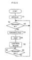
- step S1 of Fig. 5 the settings for the entire coating device are initialized.
- step S2 a transport mechanism (not shown) transports the substrate P to the substrate holding mechanism (4). After the substrate P is transported into position, the substrate P is held by vacuum suction by the substrate holding mechanism (4) in step S3.
- step S4 The coating process is carried out in step S4, shown in Fig. 6.
- step S4 the nozzle (7) is moved to a predetermined start position at step S10 in Fig. 6.
- the nozzle (7) is arranged at a predetermined distance from one edge of the substrate P, as shown in Fig. 7.
- step S11 photoresist liquid is released from the slit (20) of the nozzle (7) to the substrate P.
- the controller (23) adjusts the 3-way valve (14) to the supply setting and further opens the photoresist liquid supply valve (18) to supply photoresist liquid from the liquid tank (12) to the nozzle (7).
- step S12 the movement of the movable frame (9), support arm (8) and nozzle (7) begins horizontally relative to the movement guide (10) and, as shown in Fig. 2 and 3, photoresist liquid D is applied to the substrate P.
- step S13 it is determined whether or not the nozzle (7) has moved in the first direction d 1 a predetermined distance from right edge of substrate P.
- the 3-way valve (14) is switched to cut off the flow of nitrogen gas into the pressure tank (11), and the photoresist liquid supply valve (18) is closed stopping the supply of photoresist liquid D in step S14.
- step S15 movement of the nozzle (7) is stopped. Then, as shown in Fig. 6, the nozzle (7) is moved to a predetermined protective position away from the substrate P so as not to interfere with subsequent operations in step S16.
- step S17 the motor mechanism (26) rotates the substrate holding mechanism (4), and the substrate P, at a low speed in a direction shown by the arrow in Fig. 8.
- the substrate P is then rotated continuously for a predetermined time period.
- centrifugal force is created by the rotation of the substrate holding mechanism (4), the centrifugal force affecting the photoresist liquid D on the upper surface of the substrate P moving the fluid D in an outer peripheral direction.
- the photoresist liquid D diffuses evenly about the entire surface region of the substrate P forming a generally uniform photoresist liquid layer on the upper surface of the substrate P with an even thickness.
- the rotation of the substrate P is continued until a predetermined time has passed. Once the predetermined time has passed, the rotation of the motor mechanism (26) is stopped in step S19. Once rotation is stopped, the operation returns to the main routine in Fig. 5.
- step S5 of Fig. 5 the vacuum suction of substrate holding mechanism (4) is released. Thereafter, the transport mechanism (not shown) transfers the coated substrate P out and away from the substrate holding mechanism (4). Then the operation returns to step S2 and waits for the arrival of the next substrate P
- the substrate P is rectangular.
- the substrate W is preferable for the substrate W to be disc shaped.
- a nozzle (41) is disposed over a rotatable substrate holding mechanism (40).
- the nozzle (41) has a slit (42), the length of which is shorter than the diameter of a disc-shaped substrate W.
- the nozzle supplies a photoresist liquid (D) to a specified region smaller than the entire surface of the substrate W while the substrate holding mechanism (40) is rotated at a relatively low speed.
- the nozzle (41) is retracted to a predetermined position away from the substrate so as not to interfere with subsequent steps, and the substrate holding mechanism (40) is rotated at a relatively high speed. As shown in Fig. 10 (b), centrifugal force distribute the photoresist liquid D over the entire surface of the substrate W resulting in a photoresist layer having a predetermined thickness.
- the slit (20) of the nozzle (7) may be replaced with a plurality of needle-like liquid supply portions arranged in the longitudinal direction on the tip of the nozzle (7) or similarly with a plurality of narrow liquid supply holes H as is shown in Fig. 11.
- the rotation of the substrate holding mechanism causes movement of photoresist liquid D applied to the surface of the substrate P.
- the liquid is supplied to a region of the surface of the substrate that is smaller than the entire region of the substrate surface.
- the rotation of the substrate P causes the photoresist liquid D to evenly cover the entire surface of the substrate and a relatively small amount of excess liquid may be thrown from the substrate surface due to the rotation of the substrate P. Consequently, even though the amount of photoresist liquid applied to the surface of the substrate P is small, photoresist liquid can be diffused over the entire surface of the substrate, creating a photoresist layer having a specified thickness.
- the liquid supply nozzle of the present invention liquid can be easily supplied at a specified region.
- the coating device may be of simpler construction providing a method for moving the nozzle over the surface of the substrate, as opposed to a movable substrate holding portion.
- the nozzle has a liquid storing chamber the liquid can be more evenly supplied.
- liquid can easily be supplied to an entire specified surface.
Landscapes
- Physics & Mathematics (AREA)
- General Physics & Mathematics (AREA)
- Exposure Of Semiconductors, Excluding Electron Or Ion Beam Exposure (AREA)
- Application Of Or Painting With Fluid Materials (AREA)
- Coating Apparatus (AREA)
- Spray Control Apparatus (AREA)
Claims (1)
- Beschichtungsverfahren zur Beschichtung einer Oberfläche eines rechteckigen Substrats mit einer bestimmten Behandlungsflüssigkeit, welches folgende Verfahrensschritte aufweist:Anordnen eines rechteckigen Substrats in einer horizontalen Stellung;Durchführen eines Flüssigkeitsabgabevorgangs auf eine horizontale Oberfläche des Substrats durch Abgabe einer bestimmten Behandlungsflüssigkeit auf diese durch eine Flüssigkeitszuführdüse mit einem Auslaß, der durch einen langgestreckten Schlitz (20) gebildet ist, welcher sich parallel zu der Oberfläche und senkrecht zu einem ersten Rand des Substrats über eine Länge, die kürzer als die Breite des Substrats genommen in Richtung senkrecht zu dem ersten Rand ist, erstreckt, unter Bewegen der Düse relativ zum Substrat in eine Richtung parallel zu dem ersten Rand des Substrats, wobei die Abgabe von Behandlungsflüssigkeit auf das Substrat in einem Abstand weg von einem zweiten Rand des Substrats, der senkrecht zu dem ersten Rand ist, begonnen und in einem Abstand vor einem dritten Rand des Substrats, der parallel zu dem zweiten Rand ist, beendet wird, undrasches Drehen des Substrats mit der auf dieses abgegebenen Behandlungsflüssigkeit um eine vertikale Achse nach Abschluss des Abgabevorgangs.
Applications Claiming Priority (3)
| Application Number | Priority Date | Filing Date | Title |
|---|---|---|---|
| JP77653/94 | 1994-04-15 | ||
| JP6077653A JPH07284715A (ja) | 1994-04-15 | 1994-04-15 | 処理液塗布装置及び処理液塗布方法 |
| JP7765394 | 1994-04-15 |
Publications (3)
| Publication Number | Publication Date |
|---|---|
| EP0677334A1 EP0677334A1 (de) | 1995-10-18 |
| EP0677334B1 EP0677334B1 (de) | 2000-08-02 |
| EP0677334B2 true EP0677334B2 (de) | 2005-03-30 |
Family
ID=13639852
Family Applications (1)
| Application Number | Title | Priority Date | Filing Date |
|---|---|---|---|
| EP95105671A Expired - Lifetime EP0677334B2 (de) | 1994-04-15 | 1995-04-13 | Beschichtungsverfahren |
Country Status (6)
| Country | Link |
|---|---|
| US (1) | US5782978A (de) |
| EP (1) | EP0677334B2 (de) |
| JP (1) | JPH07284715A (de) |
| KR (1) | KR100205477B1 (de) |
| DE (1) | DE69518183T3 (de) |
| TW (1) | TW351684B (de) |
Families Citing this family (20)
| Publication number | Priority date | Publication date | Assignee | Title |
|---|---|---|---|---|
| DE19619678C1 (de) | 1996-05-15 | 1997-11-20 | Steag Hamatech Gmbh Machines | Verfahren und Vorrichtung zum Beschichten von scheibenförmigen Informationsspeichermedien |
| US6129042A (en) * | 1996-11-08 | 2000-10-10 | Coburn Optical Industries, Inc. | Process and machine for coating ophthalmic lenses |
| KR100271759B1 (ko) * | 1997-07-25 | 2000-12-01 | 윤종용 | 포토레지스트코팅장치및방법 |
| US6689215B2 (en) | 1998-09-17 | 2004-02-10 | Asml Holdings, N.V. | Method and apparatus for mitigating cross-contamination between liquid dispensing jets in close proximity to a surface |
| US6248171B1 (en) | 1998-09-17 | 2001-06-19 | Silicon Valley Group, Inc. | Yield and line width performance for liquid polymers and other materials |
| TW464970B (en) | 1999-04-21 | 2001-11-21 | Sharp Kk | Ultrasonic cleaning device and resist-stripping device |
| US6382849B1 (en) * | 1999-06-09 | 2002-05-07 | Tokyo Electron Limited | Developing method and developing apparatus |
| US6746826B1 (en) | 2000-07-25 | 2004-06-08 | Asml Holding N.V. | Method for an improved developing process in wafer photolithography |
| US6877972B2 (en) * | 2001-10-16 | 2005-04-12 | Lear Corporation | Spray urethane tool and system |
| DE102004053139A1 (de) * | 2004-11-03 | 2006-06-01 | Süss Microtec Lithography Gmbh | Drehbare Vorrichtung zum Halten eines Substrats |
| KR100780718B1 (ko) | 2004-12-28 | 2007-12-26 | 엘지.필립스 엘시디 주식회사 | 도포액 공급장치를 구비한 슬릿코터 |
| KR100700181B1 (ko) | 2004-12-31 | 2007-03-27 | 엘지.필립스 엘시디 주식회사 | 노즐대기부를 구비한 슬릿코터 및 이를 이용한 코팅방법 |
| KR100675643B1 (ko) | 2004-12-31 | 2007-02-02 | 엘지.필립스 엘시디 주식회사 | 슬릿코터 |
| KR100724190B1 (ko) | 2005-12-28 | 2007-05-31 | 동부일렉트로닉스 주식회사 | 포토레지스트 도포장치 |
| KR100819095B1 (ko) * | 2006-11-03 | 2008-04-02 | 삼성전자주식회사 | 포토스피너설비의 분사제어장치 |
| JP2012076045A (ja) * | 2010-10-04 | 2012-04-19 | Tokyo Ohka Kogyo Co Ltd | 塗布装置 |
| WO2012051485A1 (en) * | 2010-10-16 | 2012-04-19 | Cambridge Nanotech Inc. | Ald coating system |
| CN103246165B (zh) * | 2013-04-25 | 2015-03-25 | 深圳市华星光电技术有限公司 | 一种光阻涂布装置及其涂布方法 |
| JP6423672B2 (ja) * | 2014-09-26 | 2018-11-14 | 株式会社Screenホールディングス | 基板処理装置および基板処理方法 |
| CN114392880B (zh) * | 2021-12-13 | 2022-12-13 | 华玻视讯(珠海)科技有限公司 | 一种液晶屏生产用智能化对齐胶合装置 |
Citations (5)
| Publication number | Priority date | Publication date | Assignee | Title |
|---|---|---|---|---|
| JPS58170565A (ja) † | 1982-03-30 | 1983-10-07 | Fujitsu Ltd | レジスト塗布方法 |
| JPH02290277A (ja) † | 1989-02-17 | 1990-11-30 | Dainippon Printing Co Ltd | 粘性液体の塗布方法および塗布装置 |
| JPH04118073A (ja) † | 1990-09-06 | 1992-04-20 | Sharp Corp | コーティング装置 |
| JPH05158055A (ja) † | 1991-10-08 | 1993-06-25 | Tokyo Electron Ltd | 処理装置 |
| JPH0623313A (ja) † | 1992-01-31 | 1994-02-01 | Origin Electric Co Ltd | スピンコーティング方法およびその装置 |
Family Cites Families (20)
| Publication number | Priority date | Publication date | Assignee | Title |
|---|---|---|---|---|
| JPS5349955A (en) * | 1976-10-18 | 1978-05-06 | Fuji Photo Film Co Ltd | Spin coating method |
| JPS6053675B2 (ja) * | 1978-09-20 | 1985-11-27 | 富士写真フイルム株式会社 | スピンコ−テイング方法 |
| US4451507A (en) * | 1982-10-29 | 1984-05-29 | Rca Corporation | Automatic liquid dispensing apparatus for spinning surface of uniform thickness |
| US4851263A (en) * | 1986-10-23 | 1989-07-25 | Mitsubishi Kinzoku Kabushiki Kaisha | Method and apparatus for application of wax on wafers |
| JPS63209769A (ja) * | 1987-02-26 | 1988-08-31 | Asahi Glass Co Ltd | スピンナ塗布方法及びその装置 |
| JPH0669545B2 (ja) * | 1987-11-23 | 1994-09-07 | タツモ株式会社 | 塗布装置 |
| KR970007060B1 (ko) * | 1989-02-17 | 1997-05-02 | 다이닛뽕 인사쓰 가부시끼가이샤 | 점성액체의 도포방법 및 도포장치 |
| US5094884A (en) * | 1990-04-24 | 1992-03-10 | Machine Technology, Inc. | Method and apparatus for applying a layer of a fluid material on a semiconductor wafer |
| US5215622A (en) * | 1990-04-18 | 1993-06-01 | Krones Ag Hermann Kronseder Maschinenfabrik | Labeling machine for bottles or the like |
| US5234499A (en) * | 1990-06-26 | 1993-08-10 | Dainippon Screen Mgf. Co., Ltd. | Spin coating apparatus |
| JP2533401B2 (ja) * | 1990-06-26 | 1996-09-11 | 大日本スクリーン製造株式会社 | 回転式塗布装置 |
| JPH0499266A (ja) * | 1990-08-09 | 1992-03-31 | Toshiba Emi Ltd | 真空蒸着方法 |
| JP2892476B2 (ja) * | 1990-09-14 | 1999-05-17 | 東京エレクトロン株式会社 | 帯状液体ノズル及び液処理装置及び液処理方法 |
| KR100230753B1 (ko) * | 1991-01-23 | 1999-11-15 | 도꾜 일렉트론 큐슈리미티드 | 액도포 시스템 |
| JPH04332116A (ja) * | 1991-05-02 | 1992-11-19 | Mitsubishi Electric Corp | 回転塗布装置 |
| JP2633106B2 (ja) * | 1991-05-24 | 1997-07-23 | シャープ株式会社 | レジスト塗布装置 |
| US5156681A (en) * | 1991-05-28 | 1992-10-20 | Eaton Corporation | Process module dispense arm |
| JPH05136040A (ja) * | 1991-11-15 | 1993-06-01 | Toshiba Corp | フオトレジスト塗布装置 |
| JPH05166713A (ja) * | 1991-12-19 | 1993-07-02 | Toshiba Corp | 回転塗布装置 |
| NL9201824A (nl) * | 1992-10-21 | 1994-05-16 | Od & Me Bv | Inrichting voor het aanbrengen van een laklaag op een schijfvormige registratiedrager. |
-
1994
- 1994-04-15 JP JP6077653A patent/JPH07284715A/ja active Pending
-
1995
- 1995-04-13 EP EP95105671A patent/EP0677334B2/de not_active Expired - Lifetime
- 1995-04-13 DE DE69518183T patent/DE69518183T3/de not_active Expired - Lifetime
- 1995-04-13 KR KR1019950008723A patent/KR100205477B1/ko not_active Expired - Lifetime
- 1995-05-03 TW TW084104417A patent/TW351684B/zh not_active IP Right Cessation
-
1997
- 1997-06-16 US US08/876,866 patent/US5782978A/en not_active Expired - Lifetime
Patent Citations (5)
| Publication number | Priority date | Publication date | Assignee | Title |
|---|---|---|---|---|
| JPS58170565A (ja) † | 1982-03-30 | 1983-10-07 | Fujitsu Ltd | レジスト塗布方法 |
| JPH02290277A (ja) † | 1989-02-17 | 1990-11-30 | Dainippon Printing Co Ltd | 粘性液体の塗布方法および塗布装置 |
| JPH04118073A (ja) † | 1990-09-06 | 1992-04-20 | Sharp Corp | コーティング装置 |
| JPH05158055A (ja) † | 1991-10-08 | 1993-06-25 | Tokyo Electron Ltd | 処理装置 |
| JPH0623313A (ja) † | 1992-01-31 | 1994-02-01 | Origin Electric Co Ltd | スピンコーティング方法およびその装置 |
Also Published As
| Publication number | Publication date |
|---|---|
| DE69518183T3 (de) | 2006-01-12 |
| TW351684B (en) | 1999-02-01 |
| KR100205477B1 (ko) | 1999-07-01 |
| EP0677334A1 (de) | 1995-10-18 |
| DE69518183D1 (de) | 2000-09-07 |
| JPH07284715A (ja) | 1995-10-31 |
| KR950030213A (ko) | 1995-11-24 |
| US5782978A (en) | 1998-07-21 |
| DE69518183T2 (de) | 2001-04-05 |
| EP0677334B1 (de) | 2000-08-02 |
Similar Documents
| Publication | Publication Date | Title |
|---|---|---|
| EP0677334B2 (de) | Beschichtungsverfahren | |
| KR960002242B1 (ko) | 도포장치 및 방법 | |
| EP0110558B1 (de) | Verfahren und Einrichtung zur Verwendung beim Entwickeln von Schutzlackschichten | |
| CN100595887C (zh) | 涂敷设备和涂敷方法 | |
| EP0454314A2 (de) | Vorrichtung und Verfahren zum Beschichten von fliessfähigen Materialien auf Halbleiterscheibe | |
| KR100221698B1 (ko) | 기판 현상방법 및 그 장치 | |
| US7553374B2 (en) | Coating treatment apparatus and coating treatment method | |
| JP2006524131A (ja) | リニアレールコーティング装置及び方法 | |
| JPS59208831A (ja) | 塗布装置 | |
| JP2002151455A (ja) | 半導体ウエハ用洗浄装置 | |
| KR101097490B1 (ko) | 광학 제어기를 갖는 재순환 스핀 코터 | |
| EP0353280A1 (de) | Vorrichtung und verfahren zum beschichten interner hohlkörper | |
| JP3739225B2 (ja) | 基板処理装置 | |
| JP3458063B2 (ja) | 塗布装置及び塗布方法 | |
| US6752544B2 (en) | Developing apparatus and developing method | |
| JP2815064B2 (ja) | 半導体ウエハに液を塗布する塗布装置及び塗布方法 | |
| US12283499B2 (en) | Method and/or system for coating a substrate | |
| JPH09320950A (ja) | 基板処理装置 | |
| JP7506985B2 (ja) | 液処理装置及び液処理方法 | |
| JP3004824U (ja) | 流体塗布装置 | |
| JP2642434B2 (ja) | 塗布装置 | |
| JP3490283B2 (ja) | 厚膜形成装置及び厚膜形成方法 | |
| JP2001179157A (ja) | 液体の塗布ノズル及び塗布装置及び塗布方法 | |
| JP4001207B2 (ja) | 基板現像装置 | |
| JPS63294965A (ja) | 回転塗布装置 |
Legal Events
| Date | Code | Title | Description |
|---|---|---|---|
| PUAI | Public reference made under article 153(3) epc to a published international application that has entered the european phase |
Free format text: ORIGINAL CODE: 0009012 |
|
| AK | Designated contracting states |
Kind code of ref document: A1 Designated state(s): DE FR GB |
|
| 17P | Request for examination filed |
Effective date: 19960124 |
|
| 17Q | First examination report despatched |
Effective date: 19970916 |
|
| GRAG | Despatch of communication of intention to grant |
Free format text: ORIGINAL CODE: EPIDOS AGRA |
|
| GRAG | Despatch of communication of intention to grant |
Free format text: ORIGINAL CODE: EPIDOS AGRA |
|
| GRAG | Despatch of communication of intention to grant |
Free format text: ORIGINAL CODE: EPIDOS AGRA |
|
| GRAH | Despatch of communication of intention to grant a patent |
Free format text: ORIGINAL CODE: EPIDOS IGRA |
|
| GRAH | Despatch of communication of intention to grant a patent |
Free format text: ORIGINAL CODE: EPIDOS IGRA |
|
| GRAA | (expected) grant |
Free format text: ORIGINAL CODE: 0009210 |
|
| AK | Designated contracting states |
Kind code of ref document: B1 Designated state(s): DE FR GB |
|
| REF | Corresponds to: |
Ref document number: 69518183 Country of ref document: DE Date of ref document: 20000907 |
|
| ET | Fr: translation filed | ||
| PLAV | Examination of admissibility of opposition |
Free format text: ORIGINAL CODE: EPIDOS OPEX |
|
| PLBQ | Unpublished change to opponent data |
Free format text: ORIGINAL CODE: EPIDOS OPPO |
|
| PLBI | Opposition filed |
Free format text: ORIGINAL CODE: 0009260 |
|
| PLAV | Examination of admissibility of opposition |
Free format text: ORIGINAL CODE: EPIDOS OPEX |
|
| PLBF | Reply of patent proprietor to notice(s) of opposition |
Free format text: ORIGINAL CODE: EPIDOS OBSO |
|
| 26 | Opposition filed |
Opponent name: INSTITUTE OF TECHNOLOGICAL INFORMATION INC. Effective date: 20010502 |
|
| PLBF | Reply of patent proprietor to notice(s) of opposition |
Free format text: ORIGINAL CODE: EPIDOS OBSO |
|
| REG | Reference to a national code |
Ref country code: GB Ref legal event code: IF02 |
|
| PLBF | Reply of patent proprietor to notice(s) of opposition |
Free format text: ORIGINAL CODE: EPIDOS OBSO |
|
| PLBC | Reply to examination report in opposition received |
Free format text: ORIGINAL CODE: EPIDOSNORE3 |
|
| RTI2 | Title (correction) |
Free format text: COATING METHOD |
|
| PUAH | Patent maintained in amended form |
Free format text: ORIGINAL CODE: 0009272 |
|
| STAA | Information on the status of an ep patent application or granted ep patent |
Free format text: STATUS: PATENT MAINTAINED AS AMENDED |
|
| 27A | Patent maintained in amended form |
Effective date: 20050330 |
|
| AK | Designated contracting states |
Kind code of ref document: B2 Designated state(s): DE FR GB |
|
| ET3 | Fr: translation filed ** decision concerning opposition | ||
| REG | Reference to a national code |
Ref country code: DE Ref legal event code: R082 Ref document number: 69518183 Country of ref document: DE Representative=s name: KILIAN KILIAN & PARTNER, DE |
|
| PGFP | Annual fee paid to national office [announced via postgrant information from national office to epo] |
Ref country code: GB Payment date: 20140409 Year of fee payment: 20 |
|
| PGFP | Annual fee paid to national office [announced via postgrant information from national office to epo] |
Ref country code: FR Payment date: 20140409 Year of fee payment: 20 Ref country code: DE Payment date: 20140430 Year of fee payment: 20 |
|
| REG | Reference to a national code |
Ref country code: DE Ref legal event code: R071 Ref document number: 69518183 Country of ref document: DE |
|
| REG | Reference to a national code |
Ref country code: DE Ref legal event code: R071 Ref document number: 69518183 Country of ref document: DE |
|
| REG | Reference to a national code |
Ref country code: GB Ref legal event code: PE20 Expiry date: 20150412 |
|
| PG25 | Lapsed in a contracting state [announced via postgrant information from national office to epo] |
Ref country code: GB Free format text: LAPSE BECAUSE OF EXPIRATION OF PROTECTION Effective date: 20150412 |