EP0676776B1 - Kernanordnung für Ringkerntransformator - Google Patents
Kernanordnung für Ringkerntransformator Download PDFInfo
- Publication number
- EP0676776B1 EP0676776B1 EP95101724A EP95101724A EP0676776B1 EP 0676776 B1 EP0676776 B1 EP 0676776B1 EP 95101724 A EP95101724 A EP 95101724A EP 95101724 A EP95101724 A EP 95101724A EP 0676776 B1 EP0676776 B1 EP 0676776B1
- Authority
- EP
- European Patent Office
- Prior art keywords
- core
- wound core
- wound
- material strip
- coil
- Prior art date
- Legal status (The legal status is an assumption and is not a legal conclusion. Google has not performed a legal analysis and makes no representation as to the accuracy of the status listed.)
- Expired - Lifetime
Links
- 239000000463 material Substances 0.000 claims description 69
- 238000004804 winding Methods 0.000 description 49
- RYGMFSIKBFXOCR-UHFFFAOYSA-N Copper Chemical compound [Cu] RYGMFSIKBFXOCR-UHFFFAOYSA-N 0.000 description 21
- 238000010586 diagram Methods 0.000 description 19
- 238000000034 method Methods 0.000 description 10
- XEEYBQQBJWHFJM-UHFFFAOYSA-N Iron Chemical compound [Fe] XEEYBQQBJWHFJM-UHFFFAOYSA-N 0.000 description 6
- 210000003298 dental enamel Anatomy 0.000 description 6
- 229910000976 Electrical steel Inorganic materials 0.000 description 4
- 229910052802 copper Inorganic materials 0.000 description 3
- 239000010949 copper Substances 0.000 description 3
- 230000007547 defect Effects 0.000 description 3
- 230000004907 flux Effects 0.000 description 3
- 229910052742 iron Inorganic materials 0.000 description 3
- 238000005520 cutting process Methods 0.000 description 2
- 238000009413 insulation Methods 0.000 description 2
- 238000004519 manufacturing process Methods 0.000 description 2
- 238000000137 annealing Methods 0.000 description 1
- 230000007423 decrease Effects 0.000 description 1
- 230000003247 decreasing effect Effects 0.000 description 1
- 230000002542 deteriorative effect Effects 0.000 description 1
- 238000004904 shortening Methods 0.000 description 1
- 229910000859 α-Fe Inorganic materials 0.000 description 1
Images






Classifications
-
- H—ELECTRICITY
- H01—ELECTRIC ELEMENTS
- H01F—MAGNETS; INDUCTANCES; TRANSFORMERS; SELECTION OF MATERIALS FOR THEIR MAGNETIC PROPERTIES
- H01F27/00—Details of transformers or inductances, in general
- H01F27/24—Magnetic cores
- H01F27/25—Magnetic cores made from strips or ribbons
-
- H—ELECTRICITY
- H01—ELECTRIC ELEMENTS
- H01F—MAGNETS; INDUCTANCES; TRANSFORMERS; SELECTION OF MATERIALS FOR THEIR MAGNETIC PROPERTIES
- H01F41/00—Apparatus or processes specially adapted for manufacturing or assembling magnets, inductances or transformers; Apparatus or processes specially adapted for manufacturing materials characterised by their magnetic properties
- H01F41/02—Apparatus or processes specially adapted for manufacturing or assembling magnets, inductances or transformers; Apparatus or processes specially adapted for manufacturing materials characterised by their magnetic properties for manufacturing cores, coils, or magnets
- H01F41/0206—Manufacturing of magnetic cores by mechanical means
- H01F41/0213—Manufacturing of magnetic circuits made from strip(s) or ribbon(s)
Definitions
- the present invention relates to a core assembly for a toroidal transformer, the core assembly comprising a wound core being formed from shaped bands continuously cut from a material strip, a unit length of said shaped bands being wound around a jig, said wound core being longitudinally elongated in section and having no sharp corners, the core assembly comprising also a toroidal coil wound around said wound core.
- toroidal transformers employing toroidal windings, which are thin, light, and low in leakage flux, have often been used in audio equipment and in monitors of computer systems. It is required to provide wound cores that permit an improvement in the productivity of the toroidal transformers and allow the toroidal transformers to provide full performance.
- a wound core is made by winding several hundred turns of a grain-oriented silicon steel strip, about 0.2 to 0.3 mm thick, around a cylindrical jig.
- the wound core has a rectangular section with long longitudinal sides and an annular plan shape.
- the surface of the wound core is covered with an insulating film around which a copper wire such as an enameled wire is wound according to a toroidal winding technique, to form a transformer (toroidal transformer).
- the core for a toroidal transformer must be longitudinally elongated in section, to reduce the area occupied by the transformer.
- the diameter of the core must be short to reduce its weight.
- a core having a rectangular section produces a transformer which has a high ratio of iron and copper to its volume.
- the section of the wound core for the toroidal transformer is rectangular, and copper wire is wound around the wound core according to a toroidal winding technique, to form the toroidal coil. Therefore, spaces are formed between the wound core and the toroidal coil.
- the spaces between the wound core and the coil increase the size of the coil and increase the length of the copper wire, per turn, around the wound core, to increase the resistance of the coil.
- the spaces may cause noise and vibration.
- EP 0 269 347 describing a core assembly according to the preamble of claim 1 shows a wound core having a circular or an elliptic cross sections.
- This known wound core having circular or elliptic section employs a cylindrical coil bobbin for winding a wire (coil).
- This wound core comprises circular longitudinal ends and elliptic starting- and ending parts in section.
- WO-A-83/02194 discloses a wound core with a circular section having polygonal longitudinal ends and beveled corners in section.
- EP-A-0 586 246 disclosed a wound core with a circular section having polyonal starting part and ending part in section.
- DE-A-36 03 473 refers to a wound core having an elliptic section and FR-A-2 642 566 discloses a wound core having curved corners.
- a core assembly for a toroidal transformer comprising a wound core being formed from shaped bands continuously cut from a material strip, a unit length of said shaped bands being wound around a jig, said wound core being longitudinally elongated in section and having no sharp corners, the core assembly comprising also a toroidal coil wound around said wound core, in which the ratio of long side to short side of the core section is 1:0.9 to 0.3, and in which the toroidal coil is closely wound around the core without leaving any space between coil and core.
- a wound core for a toroidal transformer having an area occupied by the toroidal transformer being reduced by winding the coil closely around the core avoiding thereby any space between coil and core.
- the size of the coil can be minimized, a resistance of the coil can be suppressed, and noise and vibration of the toroidal transformer can be prevented.
- a wound core for a toroidal transformer wherein said jig is cylindrical and is turned around its axis to wind a unit length of said shaped bands around said jig, to form said wound core.
- a wound core for a toroidal transformer wherein a longitudinal center line of each said shaped bands is aligned with the widthwise center of said jig, and a unit length of said shaped bands is wound around said jig.
- a wound core for a toroidal transformer wherein said material strip is cut into said shaped bands with the maximum and minimum widths of a first band of said shaped bands being substantially adjacent to the minimum and maximum widths of a second band of said shaped bands.
- a wound core for a toroidal transformer wherein said material strip is cut into said shaped bands with a linear side-edge of said material strip serving, as it is, as a linear side-edge of one or two of said shaped bands.
- a wound core for a toroidal transformer wherein said material strip is cut into two shaped bands with each linear side-edge of said material strip serving as it is, as a linar side-edge of each said shaped bands, and with narrowed and widened parts of a first band of said sharped bands being substantially adjacent to widened and narrowed parts of a second band of said shaped bands, so that a remainder of said material strip between said first and second shaped bands is discarded.
- a wound core for a toroidal transformer comprising said toroidal winding and said woind core.
- Figure 1 shows a plan view of an example of a wound core for a toroidal transformer according to a prior art
- Fig. 1B shows a cross-section of the the wound core cut along a line 1B-1B shown in Fig. 1A.
- the wound core is made of a grain-oriented silicon steel strip and involves a starting part 111a of winding and an ending part 111b of winding.
- the wound core also involves an upper part 111c and a lower part 111d.
- the wound core has a toroidal winding (toroidal coil) 200.
- the wound core 111 is made by winding several hundred turns of a grain-oriented silicon steel strip, about 0.2 to 0.3 mm thick, around a cylindrical jig (with reference to Figs. 6A and 6B).
- the wound core 111 has a rectangular section with long longitudinal sides and an annular plan shape, as shown in Figs. 1A and 1B.
- the surface of the wound core 111 is covered with an insulating film around which a copper wire such as an enameled wire 200 is wound according to a toroidal winding technique, to form the transformer.
- An ideal sectional shape of a core of a winding is a circle.
- Many patent and utility model applications have disclosed wound cores having a circular section.
- JPP'289 corresponds to U.S. Patent Nos. 5,115,703 and 5,188,305.
- the core for a toroidal transformer must be longitudinally elongated in section, to reduce the area occupied by the transformer.
- the diameter of the core must be small to reduce its weight.
- a core having a rectangular section has a high ratio of iron and copper to the volume of the transformer. Accordingly, the ratio of long side to short side in section of the core is preferably 1:0.9 to 0.3. This is the reason why conventional toroidal transformers employ wound cores having a rectangular section such as one shown in Figs. 1A and 1B. Molded cores such as ferrite cores that are freely shaped according to molds are out of the scope of the present invention.
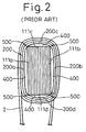
- Figure 2 shows a part of the wound core of Fig. 1B with a toroidal winding. Note that the sectional view of the wound core 111 of Fig. 2 corresponds to the right side of the wound core 111 of Fig. 1B.
- the section of the wound core 111 for the toroidal transformer is rectangular.
- a copper wire 2 is wound around the wound core 111 according to a toroidal winding technique, to form the toroidal coil 200.
- Spaces 400 are formed between the inner side (starting part) 111a of the wound core 111 and an innermost part 200a of the inner side of the coil 200, between the outside (ending part) 111b of the wound core 111 and an innermost part 200b of the outer side of the coil 200, between an upper part 111c of the wound core 111 and an innermost part 200c of the top of the coil 200, and between a lower part 111d of the wound core 111 and an innermost part 200d of the bottom of the coil 200.
- the spaces 400 between the wound core 111 and the coil 200 increase the size of the coil 200 and elongate the length of the copper wire per turn around the wound core 111, to increase the resistance of the coil.
- the spaces 400 may cause noise and vibration.
- the toroidal coil 200 is in contact with corners 500 of the wound core 111 and is bent at the corners.
- the wire 2 (coil 200) is forcibly attached to the wound core 111 by pulling the wire 2.
- the excessive stress applied to the wire 2 at the corners may damage an enamel coat of the wire 2 and cause strain in the wire 2.
- the strain increases the natural resistance of copper, to increase the resistance of the coil and to reduce the quality of the sound from audio equipment that uses the toroidal transformer.
- the coil winding is very important.
- An irregularly wound coil involves uneven winding density to cause a flux leakage. Accordingly, the coil winding work takes a long time. This problem is said to be unavoidable in manufacturing conventional toroidal transformers.
- the trouble may be solved if the corners of a wound core for the toroidal transformer are removed.
- Figure 3A shows a plan view of a first embodiment of a wound core 11 for a toroidal transformer (plan view) according to the present invention
- Fig. 3B shows a cross-section of the wound core cut along a line 3B-3B shown in Fig. 3A.
- the wound core 11 is made of a material strip (with reference to Fig. 5B).
- the wound core 11 has a starting part 11a of winding, an ending part 11b of winding, an upper part 11c, and a lower part 11d.
- a toroidal winding (toroidal coil) 20 is formed around the wound core 11.
- the wound core 11 is made by winding several hundred turns of a grain-oriented silicon steel strip, for example, 0.2 to 0.3 mm thick, around a cylindrical jig (Figs. 6A and 6B).
- the wound core 11 has semicircular longitudinal ends 11c and 11d in section.
- the present invention shapes the top 111c (11c) and bottom 111d (11d) of the conventional wound core 111 (11) each into a semicircle in section.
- the sectional shape of each of the starting and ending parts 11a and 11b of the wound core 11 is curved in accordance with the semicircular upper and lower parts 11c and 11d.
- the other parts of the wound core 11 are linear, similar to the conventional wound core 111 of Fig. 1B).
- the wound core 11 of the first embodiment has an annular plan view as shown in Fig. 3A.
- the surface of the wound core 11 is covered with an insulation film around which a copper wire such as an enameled wire 2 is wound according to a toroidal winding technique, to form the toroidal transformer.
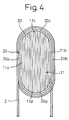
- Figure 4 shows a part of the wound core 11 of Fig. 3B with a toroidal coil 20. Note that, the wound core 11 of Fig. 4 corresponds to the right side of the wound core 11 of Fig. 3B.
- the wound core 11 has the semicircular longitudinal ends 11c and 11d in section.
- the coil 20 will never expand, and the size of the coil 20 is minimized.
- the length of the coil per turn around the wound core 11 is minimized to suppress the resistance of the winding. Since the wound core 11 is in tight contact with the coil 20, no noise nor vibration will occur.
- the present invention also solves the problems at the corners 500 of the conventional wound core 111 of Fig. 2.
- the first embodiment does not require that the coil 20 be pulled to forcibly attach the coil 20 to the wound core. Accordingly, the enamel coat of the copper wire 2 will not peel off, or the copper wire will not suffer internal strain to increase the resistance thereof. As a result, the toroidal transformer achieves full performance, and audio equipment that employs the toroidal transformer provides the expected sound quality.
- the wound core according to the first embodiment of the present invention solves the intrinsic problems of conventional toroidal transformers. Namely, the wound core of the first embodiment enables a coil to be neatly formed around the core, to realize uniform winding density, prevent a flux leakage, and shorten a winding time. The first embodiment improves the productivity of toroidal transformers.
- Figure 5A schematically shows a cross-section of the wound core of the first embodiment shown in Figs. 3A to 4, and Fig. 5B shows an example of a material strip having patterns to cut the material strip into shaped bands to form a plurality of wound cores of Fig. 5A.
- the wound core 11 of Fig. 5A corresponds to the wound core 11 of Figs. 3B and 4.
- the material strip of Fig. 5B is longitudinally scaled down by about 1/200. The same scaling down takes place also in Figs. 7B, 8B, 9B, and 10B.
- the material strip 31 is continuously cut along two cut lines 311 and 312 into shaped bands 31a and 31b.
- the wound core 11 of Fig. 5A of the first embodiment is formed by winding a predetermined unit length 310 of the shaped band 31a several hundred times around a jig 4 to be explained later.
- the jig 4 continuously forms wound cores, to improve the productivity of toroidal transformers.
- a plurality (two in Fig. 5B) of the shaped bands 31a and 31b are cut out of the material strip 31 such that the maximum and minimum widths MAX and MIN of the shaped band 31a are adjacent to the minimum and maximum widths MIN and MAX of the other band 31b.
- This arrangement improves the efficiency of use of the material strip 31. Namely, this reduces the quantity of a remainder 31c which must be discarded after the shaped bands 31a and 31b are cut out of the material strip 31. According to the first embodiment, only one part 31c is discarded.
- the shaped bands 31a and 31b are cut out of the material strip 31 such that a linear edge of the material strip 31 is used as it is as a linear edge of the shaped band 31a. This reduces the number of cut lines on the material strip 31.
- the two shaped bands 31a and 31b are cut along the two cut lines 311 and 312.
- one or two shaped bands 31a and 31b are cut out of one material strip 31 (32; 33; 34; 35). It is possible to cut many (three, four, five, and so on) shaped bands out of a single material strip.
- Figure 6 schematically shows a state of winding a shaped band around a jig to form a wound core for a toroidal transformer according to the present invention
- Fig. 6B is a diagram for explaining a winding process to form the wound core of Fig. 6A.
- Fig. 6A is a front view
- Fig. 6B is a side view seen from a reference mark B of Fig. 6A.
- a predetermined unit length 310 of the shaped band 31a of Fig. 5B is wound around the cylindrical jig 4, to form the wound core 11 for a toroidal transformer.
- the jig 4 is turned around an axis thereof, and centering guide rollers 41 (42) align the longitudinal center line 31a' of the shaped band 31a with the widthwise center 4' of the jig 4. Accordingly, even if the shaped band 31a or 31b is curved, it is correctly wound around the jig 4, to form the wound core 11 having the symmetrical upper and lower parts 11c and 11d with respect to the center line 31a' (4').
- Each side-edge of the shaped band 31a (310) is supported by the guide rollers 41 and 42, so that the center line 31a' of the shaped band 31a aligns with the center 4' of the jig 4.
- the width of the jig 4 is longer than the maximum width MAX of the shaped band 31a (310).
- the width of the jig 4 may be equal to or shorter than the maximum width of a band to be wound.
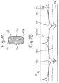
- Figure 7A schematically shows a cross-section of the wound core of a second embodiment of the present invention
- Fig. 7B shows an example of a material strip having patterns to cut the material strip into shaped bands to form a plurality of wound cores of Fig. 7A.
- the wound core 12 of the second embodiment has elliptic longitudinal ends 12c and 12d in section.
- a starting part 12a of winding and an ending part 12b of winding of the wound core 12 are elliptic.
- This configuration improves the attachment of a coil 20 to the wound core 12, thereby minimizing the size of the coil 20, suppressing the resistance of the coil, and preventing noise and vibration. It is not necessary to forcibly attach the coil 20 to the wound core 12, so that an enamel coat of the coil is not damaged, and a copper wire of the coil suffer no internal strain that may increase the resistance thereof.
- a material strip 32 is continuously cut along two cut lines 321 and 322, to form two shaped bands 32a and 32b.
- the wound core 12 is formed by aligning the center line 32b' of the shaped band 32b with the center 4' of the jig 4 (Figs 6A and 6B) and by winding each unit length 320 of the shaped band 32b around the jig 4.
- a plurality (two in Fig. 7B) of the shaped bands 32a and 32b are cut out of the material strip 32 such that the widest and narrowest portions of the band 32a are adjacent to the narrowest and widest portions of the shaped band 32b.
- a remainder 32c, between the shaped bands 32a and 32b of the material strip 32, is discarded.
- This configuration improves the efficiency of use of the material strip. Namely, the quantity of the portion 32c to be discarded after the shaped bands 32a and 32b are cut out of the material strip 32 is decreased. According to the second embodiment, only one strip 32c must be discarded.
- Fig. 7B the material strip 32 is cut such that each linear side-edge of the material strip 32 is used as one of the side-edges of each of the shaped bands 32a and 32b. This decreases the number of cut lines on the material strip 32. According to the embodiment of Fig. 7B, the two cut lines 321 and 322 are sufficient to cut the two shaped bands 32a and 32b.
- Figure 8A schematically shows a cross-section of the wound core of a third embodiment of the present invention
- Fig. 8B shows an example of a material strip having patterns to cut the material strip into shaped bands to form a plurality of wound cores of Fig. 8A.
- the wound core 13 of the third embodiment has an elliptic section.
- the wound core 13 has elliptic longitudinal ends 13c and 13d.
- a starting part 13a of winding and an ending part 13b of winding of the wound core 13 are also elliptic in section.
- This configuration further improves the attachment a coil 20 to the wound core 13, thereby minimizing the size of the coil 20, suppressing the resistance of the coil, and preventing noise or vibration.
- the coil 20 is never forcibly attached to the wound core 13, so that the enamel coat of the coil 20 is not broken, nor does the copper wire of the coil suffer internal strain that may increase the resistance thereof.
- a material strip 33 is continuously cut along three cut lines 331, 332, and 333 into two shaped bands 33a and 33b.
- the wound core 13 is formed by winding a predetermined unit length 330 of the shaped band 33a around the jig 4 (Figs. 6A and 6B) while aligning the center line 33a' of the shaped band 33a with the center 4' of the jig 4.
- a plurality (two in Fig. 8B) of the shaped bands 33a and 33b are cut out of the material strip 33 such that the maximum and minimum widths MAX and MIN of the shaped band 33a are adjacent to the minimum and maximum widths MIN and MAX of the other shaped band 33b.
- This configuration improves the efficiency of use of the material strip 33. Namely, the remainders 33c and 33d, to be discarded after the shaped bands 33a and 33b are cut out of the material strip 33, are minimized. According to the third embodiment, there are two remainders 31c and 31d to be discarded. If the material strip 33 has defects on each edge, the defects may be positioned in the parts 31c and 31d to be discarded. Namely, the shaped bands 33a and 33b will not involve the defects, to maintain the quality of the wound core 13.
- Figure 9A schematically shows a cross-section of the wound core of a fourth embodiment of the present invention
- Fig. 9B shows an example of a material strip having patterns to cut the material strip into shaped bands to form a plurality of wound cores of Fig. 9A.
- the wound core 14 has curved corners 14e, 14f, 14g, 14h in section.
- This configuration improves the attachment of a coil 20 to the wound core 13 further than the prior art of Figs. 1A to 2, thereby minimizing the size of the coil 20, suppressing the resistance of the coil, and preventing noise and vibration. It is not necessary to forcibly attach the coil 20 to the wound core 13, so that the enamel coat of the coil 20 is not damaged, or a copper wire of the coil suffer no internal strain that may increase the resistance thereof.
- the material strip 34 is continuously cut along a cut line 341 into a shaped band 34a.
- the wound core 14 is formed by winding a predetermined unit length 340 of the shaped band 34a around the jig 4 (Figs. 6A and 6B) with the center line 34a' of the shaped band 34a being aligned with the center 4' of the jig 4.
- the fourth embodiment cuts the shaped band 34a out of the material strip 34 such that a linear side-edge of the material strip 34 is left as it is as a linear side-edge of the shaped band 34a. This results in reducing the number of cut lines on the material strip 34. According to the embodiment of Fig. 9B, the single cut line 341 is sufficient to cut the shaped band 34a out of the material strip 34.
- Figure 10A schematically shows a cross-section of the wound core of a fifth embodiment of the present invention
- Fig. 10B shows an example of a material strip having patterns to cut the material strip into shaped bands to form a plurality of wound cores of Fig. 10A.
- the wound core 15 of the fifth embodiment has linearly beveled corners 15e, 15f, 15g, and 15h in section.
- the wound core 15 of the fifth embodiment has polygonal longitudinal ends 15c and 15d in section.
- a starting part 15a of winding and an ending part 15b of winding of the wound core 15 are also polygonal in section.
- the sectional shape of the wound core of this embodiment may be hexagonal, octagonal, dodecagonal, or any other suitable shape.
- a coil (toroidal coil) 20 to the wound core 15 is improved further than the prior art of Figs. 1A to 2, thereby minimizing the size of the coil 20, suppressing the resistance of the coil, and preventing noise and vibration. It is not necessary to forcibly attach the coil 20 to the wound core 15, so that an enamel coat of the coil is not damaged, and a copper wire of the coil does not suffer internal strain that may increase the resistance thereof.
- the fifth embodiment is suitable when the coil 20 must not be attached to the wound core too tightly, in order to reduce the electrostatic capacitance between the wound core and the coil, and at the same time, to solve the problems of the conventional wound core having a rectangular section.
- a material strip 35 is continuously cut along a cut line 351 into a shaped band 35a.
- the wound core 15 of the fifth embodiment of Fig. 10A is produced by winding a predetermined unit length 350 of the shaped band 35a around the jig 4 (Figs. 6A and 6B) with the center line 35a' of the band 35a being aligned with the center 4' of the jig 4.
- the fifth embodiment uses a linear side-edge of the material strip 35 as it is as a linear side-edge of the shaped band 35a. This reduces the number of cut lines on the material strip.35. According to the embodiment of Fig. 10B, the single cut line 351 is sufficient to cut the shaped band 35a from the material strip.
- This embodiment properly fits a copper wire of the coil around the wound core without applying excessive stress to the copper wire, thereby preventing distortion of the copper wire, shortening the length of the copper wire per turn, and neatly arranging the coil to improve the space factor.
- This embodiment is effective in solving the problems of the conventional wound core having a rectangular section, making the winding work easier, improving the productivity of wound cores, and allowing the toroidal transformer that employs this wound core to achieve full performance.
- a wound core according to the present invention has an improved shape to properly attach a coil to the wound core.
- This wound core allows a toroidal transformer that employs the wound core achieve to full performance, and improves the productivity of the toroidal transformers.
Landscapes
- Engineering & Computer Science (AREA)
- Power Engineering (AREA)
- Manufacturing & Machinery (AREA)
- Coils Or Transformers For Communication (AREA)
- Manufacturing Cores, Coils, And Magnets (AREA)
- Coils Of Transformers For General Uses (AREA)
Claims (7)
- Kernanordnung für einen Ringkerntransformator, wobei die Kernanordnung einen gewickelten Kern (11; 12; 13; 15) umfaßt, der aus Profilbändern (31a; 31b; 32a; 32b; 33a; 33b; 34a; 35a) gebildet ist, welche kontinuierlich aus einem Materialstreifen (31; 32; 33; 34; 35) ausgeschnitten werden, wobei eine Einheitslänge (310; 320; 330; 340; 350) der Profilbänder (31a; 31b; 32a; 32b; 33a; 33b; 34a; 35a) um eine Vorrichtung (4) herumgewickelt ist, wobei der gewickelte Kern (11; 12; 13; 15) dem Querschnitt nach in Längsrichtung in die Länge gezogen ist und keine scharfen Ecken aufweist, wobei die Kernanordnung des weiteren eine Ringspule (20) umfaßt, die um den gewickelten Kern (11; 12; 13; 15) gewickelt ist, dadurch gekennzeichnet, daß das Verhältnis von langer Seite zu kurzer Seite des Kernquerschnittes 1:0,9 bis 0,3 beträgt und daß die Ringspule (20) eng um den Kern (11; 12; 13; 15) gewickelt ist, ohne zwischen Spule (20) und Kern (11; 12; 13; 15) einen Zwischenraum freizulassen.
- Kernanordnung nach Anspruch 1; wobei die Vorrichtung (4) zylindrisch ist und um ihre Achse gedreht wird, um eine Einheitslänge (310; 320; 330; 340; 350) der Profilbänder (31a; 31b; 32a; 32b; 33a; 33b; 34a; 35a) um die Vorrichtung (4) zu wickeln, um den gewickelten Kern zu bilden.
- Kernanordnung nach Anspruch 1 oder 2, wobei eine in Längsrichtung verlaufende Mittellinie (31a'; 32b'; 33a'; 34a'; 35a') jedes der Profilbänder (31a; 31b; 32a; 32b; 33a; 33b; 34a; 35a) mit der breitenbezogenen Mitte (4') der Vorrichtung (4) ausgefluchtet wird und eine Einheitslänge (310; 320; 330; 340; 350) der Profilbänder (31a; 31b; 32a; 32b; 33a; 33b; 34a; 35a) um die Vorrichtung (4) gewickelt wird.
- Kernanordnung nach einem beliebigen der Ansprüche 1 bis 3, wobei der Materialstreifen (31; 33) zu den Profilbändern (31a, 31; 33a, 33b) zerschnitten wird, wobei die Höchst- und die Mindestbreite eines ersten Bandes (31a; 33a) der Profilbänder (31a; 31b; 32a; 32b; 33a; 33b; 34a; 35a) der Mindest- und der Höchstbreite eines zweiten Bandes (31b; 33b) der Profilbänder (31a; 31b; 32a; 32b; 33a; 33b; 34a; 35a) im wesentlichen benachbart liegen.
- Kernanordnung nach einem beliebigen der Ansprüche 1 bis 4, wobei der Materialstreifen (31, 32) zu den Profilbändern (31a, 31b; 32a, 32b) zerschnitten wird, wobei eine geradlinige Seitenkante des Materialstreifens (31; 32) so wie sie ist als geradlinige Seitenkante eines oder zwei der Profilbänder (31a; 32a, 32b) dient.
- Kernanordnung nach Anspruch 5, wobei der Materialstreifen (32) zu zwei Profilbändern (32a, 32b) zerschnitten wird, wobei jede der geradlinigen Seitenkanten des Materialstreifens (32) so wie sie ist als geradlinige Seitenkante je eines der Profilbänder dient, und wobei die verengten und erweiterten Teile eines ersten Bandes (32a) der Profilbänder (32a, 32b) den erweiterten und verengten Teilen eines zweiten Bandes (32b) der Profilbänder (32a, 32b) im wesentlichen gegenüberliegt, so daß ein Rest (32c) des Materialstreifens (32) zwischen dem ersten und dem zweiten Profilband (32a, 32b) weggeworfen wird.
- Ringkerntransformator, umfassend die Ringspule (20) und den gewickelten Kern (11; 12; 13; 15) gemäß einem der vorhergehenden Ansprüche.
Applications Claiming Priority (3)
| Application Number | Priority Date | Filing Date | Title |
|---|---|---|---|
| JP4601794 | 1994-03-16 | ||
| JP6046017A JP2771109B2 (ja) | 1994-03-16 | 1994-03-16 | 巻鉄心 |
| JP46017/94 | 1994-03-16 |
Publications (2)
| Publication Number | Publication Date |
|---|---|
| EP0676776A1 EP0676776A1 (de) | 1995-10-11 |
| EP0676776B1 true EP0676776B1 (de) | 1999-07-21 |
Family
ID=12735288
Family Applications (1)
| Application Number | Title | Priority Date | Filing Date |
|---|---|---|---|
| EP95101724A Expired - Lifetime EP0676776B1 (de) | 1994-03-16 | 1995-02-09 | Kernanordnung für Ringkerntransformator |
Country Status (8)
| Country | Link |
|---|---|
| US (1) | US6407655B1 (de) |
| EP (1) | EP0676776B1 (de) |
| JP (1) | JP2771109B2 (de) |
| KR (1) | KR0155447B1 (de) |
| CN (2) | CN1058803C (de) |
| DE (1) | DE69510852T2 (de) |
| ES (1) | ES2133596T3 (de) |
| TW (1) | TW335498B (de) |
Cited By (1)
| Publication number | Priority date | Publication date | Assignee | Title |
|---|---|---|---|---|
| US7124977B2 (en) | 2003-10-15 | 2006-10-24 | Actown Electrocoil, Inc. | Magnetic core winding apparatus |
Families Citing this family (16)
| Publication number | Priority date | Publication date | Assignee | Title |
|---|---|---|---|---|
| JP3794928B2 (ja) | 2000-04-17 | 2006-07-12 | 東京精電株式会社 | 低騒音・低損失リアクトル |
| US6601312B1 (en) | 2001-09-29 | 2003-08-05 | Ahmed M. Phuly | Method and apparatus for universal shape cutting of pipes |
| US6865622B2 (en) * | 2002-05-13 | 2005-03-08 | Intel Corporation | System including real-time data communication features |
| TWI276122B (en) | 2003-11-05 | 2007-03-11 | Tdk Corp | Coil device |
| US7551053B2 (en) | 2003-11-05 | 2009-06-23 | Tdk Corporation | Coil device |
| US7501955B2 (en) * | 2004-09-13 | 2009-03-10 | Avery Dennison Corporation | RFID device with content insensitivity and position insensitivity |
| KR200452287Y1 (ko) * | 2009-03-03 | 2011-02-16 | (주)동일기연 | 원통형 코일조립체 |
| JP2009296015A (ja) * | 2009-09-18 | 2009-12-17 | Sumitomo Electric Ind Ltd | 車載用電力変換装置 |
| CN101800127B (zh) * | 2010-04-12 | 2012-12-26 | 东莞市高鑫机电科技服务有限公司 | 卷绕铁芯制备方法及实施该方法制成的铁芯 |
| JP2011249699A (ja) * | 2010-05-31 | 2011-12-08 | Sht Co Ltd | 磁気コア装置及びこれを用いたコイル装置 |
| JP5757407B2 (ja) * | 2011-04-25 | 2015-07-29 | 日立金属株式会社 | カットコア |
| CN102185393B (zh) * | 2011-05-09 | 2012-12-19 | 镇江中船现代发电设备有限公司 | 大容量低压发电机定子 |
| CN102426908A (zh) * | 2011-12-19 | 2012-04-25 | 苏州博远特种变压器有限公司 | 变压器铁芯 |
| JP6491835B2 (ja) * | 2014-08-08 | 2019-03-27 | 株式会社日立製作所 | 静止誘導電器 |
| DE102017126473A1 (de) * | 2017-11-10 | 2019-05-16 | Abb Schweiz Ag | Transformator zur Verwendung in einem Schienenfahrzeug |
| JP2021119588A (ja) * | 2020-01-30 | 2021-08-12 | 岡谷電機産業株式会社 | 磁性コア |
Family Cites Families (36)
| Publication number | Priority date | Publication date | Assignee | Title |
|---|---|---|---|---|
| FR1107583A (fr) * | 1954-06-18 | 1956-01-03 | Cem Comp Electro Mec | Procédé de fabrication de circuits magnétiques à tôles enroulées |
| US3201734A (en) * | 1960-08-03 | 1965-08-17 | Fed Pacific Electric Co | Transformer core and winding |
| US3149296A (en) * | 1961-01-03 | 1964-09-15 | Gulton Ind Inc | Shielded transformer |
| US3465273A (en) | 1967-12-14 | 1969-09-02 | Hunterdon Transformer Co | Toroidal inductor |
| JPS5258818A (en) * | 1975-11-08 | 1977-05-14 | Matsushita Electric Ind Co Ltd | Core for wound-core type transformer and its preparation |
| JPS5384118A (en) * | 1976-12-29 | 1978-07-25 | Matsushita Electric Ind Co Ltd | Curve slit system and its apparatus |
| JPS5837681B2 (ja) | 1978-06-28 | 1983-08-18 | 株式会社ダイヘン | 内鉄形変圧器 |
| JPS6028375B2 (ja) | 1978-08-31 | 1985-07-04 | 昭和電線商事株式会社 | 巻鉄心製造装置 |
| NZ191840A (en) | 1978-10-19 | 1983-06-14 | L Manderson | Transformer core construction |
| JPS55132027A (en) * | 1979-04-02 | 1980-10-14 | Kitamura Kikai:Kk | Rolled core material forming device and rolled core forming device |
| JPS5680113A (en) | 1979-12-05 | 1981-07-01 | Kitamura Kikai:Kk | Cutting of band material for circular cross-sectional winding core |
| JPS5837681A (ja) * | 1981-08-31 | 1983-03-04 | セイコーインスツルメンツ株式会社 | 学習器 |
| FR2518306B1 (fr) * | 1981-12-11 | 1986-11-28 | Transfix Soc Nouv | Transformateur electrique et procede pour sa fabrication |
| JPS58201568A (ja) | 1982-05-20 | 1983-11-24 | Mitsubishi Electric Corp | 始動電動機の起動方法 |
| DE3232025A1 (de) | 1982-08-27 | 1984-03-01 | Siemens AG, 1000 Berlin und 8000 München | Ringkern fuer elektrische ringspulen und uebertrager |
| JPS59111019U (ja) * | 1983-01-17 | 1984-07-26 | 広畑電磁鋼センタ−株式会社 | 変成器用巻き鉄芯 |
| JPS6037510B2 (ja) | 1983-06-17 | 1985-08-27 | 富士通株式会社 | ロ−マ字漢字変換方式 |
| JPS603108A (ja) * | 1983-06-20 | 1985-01-09 | Kyushu Henatsuki Kk | 電気機器用鉄心 |
| JPS60111021U (ja) * | 1983-12-28 | 1985-07-27 | 北芝電機株式会社 | 巻鉄心 |
| IT1184115B (it) * | 1984-01-26 | 1987-10-22 | Gen Electric | Metodo ed apparato per dividere o tagliare un foglio di metallo amorfo |
| US4605558A (en) * | 1984-04-20 | 1986-08-12 | Wallace Shrimpton | Process for cell separation |
| DE3603473A1 (de) * | 1986-02-05 | 1987-08-06 | Flowtec Ag | Verfahren und vorrichtung zum herstellen von magnetischen ringkernen |
| JPS62247511A (ja) * | 1986-08-21 | 1987-10-28 | Kitamura Kikai:Kk | 巻鉄芯の成形装置 |
| JPS63132408A (ja) * | 1986-11-22 | 1988-06-04 | Kitamura Kiden Kk | 巻鉄心 |
| US4848684A (en) | 1986-11-22 | 1989-07-18 | Kitamura Kiden Co., Ltd. | Wound core having circular and elliptic outer surface portions |
| DE3784888T2 (de) | 1986-12-29 | 1993-06-24 | Kitamura Kiden Kk | Verfahren und vorrichtung zur herstellung eines gewickelten kernes. |
| JPS63188916A (ja) * | 1987-01-31 | 1988-08-04 | Kitamura Kiden Kk | 帯材走行位置制御装置 |
| JPH01206610A (ja) * | 1988-02-13 | 1989-08-18 | Kitamura Kiden Kk | 段付巻鉄心用帯材の切抜方法 |
| US5188305A (en) | 1988-09-27 | 1993-02-23 | Kitamura Kiden Co., Ltd. | Apparatus for cutting winding strips for use in a wound core |
| JPH0289304A (ja) * | 1988-09-27 | 1990-03-29 | Kitamura Kiden Kk | 巻鉄心用帯材の切抜方法 |
| JPH0622182B2 (ja) | 1988-10-22 | 1994-03-23 | 電気鉄芯工業株式会社 | 略円形断面巻鉄芯材料の切抜き方法 |
| GB2227888A (en) * | 1989-01-30 | 1990-08-08 | Elektrosvarki Im E O Patona Ak | Ring transformer for welding pipes |
| JPH0541327A (ja) * | 1991-08-05 | 1993-02-19 | Denki Tetsushin Kogyo Kk | 巻鉄心の製法 |
| JP2575258B2 (ja) | 1992-02-19 | 1997-01-22 | 住友ゴム工業株式会社 | 印刷用オフセットブランケット |
| JP2901413B2 (ja) * | 1992-04-22 | 1999-06-07 | 北村機電株式会社 | 巻鉄心用帯材の切り抜き装置 |
| JP2838627B2 (ja) * | 1992-09-03 | 1998-12-16 | 電気鉄芯工業株式会社 | 巻鉄心 |
-
1994
- 1994-03-16 JP JP6046017A patent/JP2771109B2/ja not_active Expired - Lifetime
-
1995
- 1995-02-09 ES ES95101724T patent/ES2133596T3/es not_active Expired - Lifetime
- 1995-02-09 DE DE69510852T patent/DE69510852T2/de not_active Expired - Fee Related
- 1995-02-09 EP EP95101724A patent/EP0676776B1/de not_active Expired - Lifetime
- 1995-02-18 TW TW084101511A patent/TW335498B/zh active
- 1995-02-27 KR KR1019950003911A patent/KR0155447B1/ko not_active Expired - Fee Related
- 1995-02-28 CN CN95100442A patent/CN1058803C/zh not_active Expired - Lifetime
- 1995-02-28 CN CN95203652U patent/CN2259674Y/zh not_active Expired - Fee Related
-
1997
- 1997-02-27 US US08/807,518 patent/US6407655B1/en not_active Expired - Fee Related
Cited By (3)
| Publication number | Priority date | Publication date | Assignee | Title |
|---|---|---|---|---|
| US7124977B2 (en) | 2003-10-15 | 2006-10-24 | Actown Electrocoil, Inc. | Magnetic core winding apparatus |
| US7154368B2 (en) | 2003-10-15 | 2006-12-26 | Actown Electricoil, Inc. | Magnetic core winding method, apparatus, and product produced therefrom |
| US7159816B2 (en) | 2003-10-15 | 2007-01-09 | Actown Electricoil, Inc. | Magnetic core winding method |
Also Published As
| Publication number | Publication date |
|---|---|
| KR0155447B1 (ko) | 1998-11-16 |
| JPH07254515A (ja) | 1995-10-03 |
| EP0676776A1 (de) | 1995-10-11 |
| ES2133596T3 (es) | 1999-09-16 |
| TW335498B (en) | 1998-07-01 |
| JP2771109B2 (ja) | 1998-07-02 |
| CN2259674Y (zh) | 1997-08-13 |
| CN1111801A (zh) | 1995-11-15 |
| US6407655B1 (en) | 2002-06-18 |
| DE69510852D1 (de) | 1999-08-26 |
| US20020063618A1 (en) | 2002-05-30 |
| HK1010419A1 (en) | 1999-06-17 |
| DE69510852T2 (de) | 1999-11-25 |
| KR950027856A (ko) | 1995-10-18 |
| CN1058803C (zh) | 2000-11-22 |
Similar Documents
| Publication | Publication Date | Title |
|---|---|---|
| EP0676776A1 (de) | Wickelkern für Ringkerntransformator | |
| US6512438B1 (en) | Inductor core-coil assembly and manufacturing thereof | |
| JP4350890B2 (ja) | セグメント化された変圧器コア | |
| CA2412346C (en) | Winding for a transformer or a coil | |
| WO1993015515A1 (en) | Three phase transformer with frame shaped winding assemblies | |
| US5168255A (en) | Three phase transformer | |
| HK1010419B (en) | Core assembly for toroidal transformer | |
| CN1038209C (zh) | 非晶合金薄带矩形铁心的制造方法 | |
| US20230411062A1 (en) | Choke coil | |
| JPS608408Y2 (ja) | フライバツクトランスの高圧ボビン | |
| WO2014117073A1 (en) | Forming amorphous metal transformer cores | |
| JPS5919394Y2 (ja) | 環状磁芯を用いた変成器 | |
| EP0657064B1 (de) | Wicklungsträgerkörper für transformatoren/drosselspulen mit supraleitern | |
| KR920007123Y1 (ko) | 트로이달 코어형 변압기 | |
| JP3079446U (ja) | 大電流用コイル。 | |
| JP2523560B2 (ja) | トランス | |
| JPH07201588A (ja) | Isdn用パルストランス | |
| JPH043474Y2 (de) | ||
| JP2874056B2 (ja) | リード付インダクターとその製造方法 | |
| JPH0429542Y2 (de) | ||
| JPH07201587A (ja) | Isdn用パルストランス | |
| CA1055128A (en) | Inductive device with bobbin and method of manufacture | |
| JP2513698Y2 (ja) | トランス | |
| JPH0670519A (ja) | コンデンサ誘導電動機 | |
| JPH0555056A (ja) | 巻鉄心 |
Legal Events
| Date | Code | Title | Description |
|---|---|---|---|
| PUAI | Public reference made under article 153(3) epc to a published international application that has entered the european phase |
Free format text: ORIGINAL CODE: 0009012 |
|
| AK | Designated contracting states |
Kind code of ref document: A1 Designated state(s): BE CH DE ES FR GB IE IT LI SE |
|
| 17P | Request for examination filed |
Effective date: 19951109 |
|
| 17Q | First examination report despatched |
Effective date: 19960125 |
|
| GRAG | Despatch of communication of intention to grant |
Free format text: ORIGINAL CODE: EPIDOS AGRA |
|
| GRAG | Despatch of communication of intention to grant |
Free format text: ORIGINAL CODE: EPIDOS AGRA |
|
| GRAH | Despatch of communication of intention to grant a patent |
Free format text: ORIGINAL CODE: EPIDOS IGRA |
|
| GRAH | Despatch of communication of intention to grant a patent |
Free format text: ORIGINAL CODE: EPIDOS IGRA |
|
| GRAA | (expected) grant |
Free format text: ORIGINAL CODE: 0009210 |
|
| AK | Designated contracting states |
Kind code of ref document: B1 Designated state(s): BE CH DE ES FR GB IE IT LI SE |
|
| PG25 | Lapsed in a contracting state [announced via postgrant information from national office to epo] |
Ref country code: LI Free format text: LAPSE BECAUSE OF FAILURE TO SUBMIT A TRANSLATION OF THE DESCRIPTION OR TO PAY THE FEE WITHIN THE PRESCRIBED TIME-LIMIT Effective date: 19990721 Ref country code: CH Free format text: LAPSE BECAUSE OF FAILURE TO SUBMIT A TRANSLATION OF THE DESCRIPTION OR TO PAY THE FEE WITHIN THE PRESCRIBED TIME-LIMIT Effective date: 19990721 Ref country code: BE Free format text: LAPSE BECAUSE OF FAILURE TO SUBMIT A TRANSLATION OF THE DESCRIPTION OR TO PAY THE FEE WITHIN THE PRESCRIBED TIME-LIMIT Effective date: 19990721 |
|
| REG | Reference to a national code |
Ref country code: CH Ref legal event code: EP |
|
| REF | Corresponds to: |
Ref document number: 69510852 Country of ref document: DE Date of ref document: 19990826 |
|
| ET | Fr: translation filed | ||
| REG | Reference to a national code |
Ref country code: ES Ref legal event code: FG2A Ref document number: 2133596 Country of ref document: ES Kind code of ref document: T3 |
|
| REG | Reference to a national code |
Ref country code: IE Ref legal event code: FG4D |
|
| ITF | It: translation for a ep patent filed | ||
| REG | Reference to a national code |
Ref country code: CH Ref legal event code: PL |
|
| PG25 | Lapsed in a contracting state [announced via postgrant information from national office to epo] |
Ref country code: IE Free format text: LAPSE BECAUSE OF NON-PAYMENT OF DUE FEES Effective date: 20000209 |
|
| PLBE | No opposition filed within time limit |
Free format text: ORIGINAL CODE: 0009261 |
|
| STAA | Information on the status of an ep patent application or granted ep patent |
Free format text: STATUS: NO OPPOSITION FILED WITHIN TIME LIMIT |
|
| 26N | No opposition filed | ||
| REG | Reference to a national code |
Ref country code: IE Ref legal event code: MM4A |
|
| REG | Reference to a national code |
Ref country code: GB Ref legal event code: IF02 |
|
| PGFP | Annual fee paid to national office [announced via postgrant information from national office to epo] |
Ref country code: ES Payment date: 20050204 Year of fee payment: 11 |
|
| PGFP | Annual fee paid to national office [announced via postgrant information from national office to epo] |
Ref country code: FR Payment date: 20050208 Year of fee payment: 11 |
|
| PGFP | Annual fee paid to national office [announced via postgrant information from national office to epo] |
Ref country code: GB Payment date: 20050209 Year of fee payment: 11 |
|
| PGFP | Annual fee paid to national office [announced via postgrant information from national office to epo] |
Ref country code: SE Payment date: 20050215 Year of fee payment: 11 |
|
| PGFP | Annual fee paid to national office [announced via postgrant information from national office to epo] |
Ref country code: DE Payment date: 20050426 Year of fee payment: 11 |
|
| PG25 | Lapsed in a contracting state [announced via postgrant information from national office to epo] |
Ref country code: GB Free format text: LAPSE BECAUSE OF NON-PAYMENT OF DUE FEES Effective date: 20060209 |
|
| PG25 | Lapsed in a contracting state [announced via postgrant information from national office to epo] |
Ref country code: SE Free format text: LAPSE BECAUSE OF NON-PAYMENT OF DUE FEES Effective date: 20060210 Ref country code: ES Free format text: LAPSE BECAUSE OF NON-PAYMENT OF DUE FEES Effective date: 20060210 |
|
| PGFP | Annual fee paid to national office [announced via postgrant information from national office to epo] |
Ref country code: IT Payment date: 20060228 Year of fee payment: 12 |
|
| PG25 | Lapsed in a contracting state [announced via postgrant information from national office to epo] |
Ref country code: DE Free format text: LAPSE BECAUSE OF NON-PAYMENT OF DUE FEES Effective date: 20060901 |
|
| EUG | Se: european patent has lapsed | ||
| GBPC | Gb: european patent ceased through non-payment of renewal fee |
Effective date: 20060209 |
|
| REG | Reference to a national code |
Ref country code: FR Ref legal event code: ST Effective date: 20061031 |
|
| REG | Reference to a national code |
Ref country code: ES Ref legal event code: FD2A Effective date: 20060210 |
|
| PG25 | Lapsed in a contracting state [announced via postgrant information from national office to epo] |
Ref country code: FR Free format text: LAPSE BECAUSE OF NON-PAYMENT OF DUE FEES Effective date: 20060228 |
|
| PG25 | Lapsed in a contracting state [announced via postgrant information from national office to epo] |
Ref country code: IT Free format text: LAPSE BECAUSE OF NON-PAYMENT OF DUE FEES Effective date: 20070209 |