EP0675633A2 - Bildverarbeitungsgerät und -verfahren - Google Patents
Bildverarbeitungsgerät und -verfahren Download PDFInfo
- Publication number
- EP0675633A2 EP0675633A2 EP95104549A EP95104549A EP0675633A2 EP 0675633 A2 EP0675633 A2 EP 0675633A2 EP 95104549 A EP95104549 A EP 95104549A EP 95104549 A EP95104549 A EP 95104549A EP 0675633 A2 EP0675633 A2 EP 0675633A2
- Authority
- EP
- European Patent Office
- Prior art keywords
- image
- output
- signal
- input
- images
- Prior art date
- Legal status (The legal status is an assumption and is not a legal conclusion. Google has not performed a legal analysis and makes no representation as to the accuracy of the status listed.)
- Granted
Links
- 238000012545 processing Methods 0.000 title claims abstract description 173
- 238000000034 method Methods 0.000 title claims description 23
- 238000012546 transfer Methods 0.000 claims description 32
- 238000003672 processing method Methods 0.000 claims 1
- 230000003287 optical effect Effects 0.000 description 16
- 230000006870 function Effects 0.000 description 12
- 101000994667 Homo sapiens Potassium voltage-gated channel subfamily KQT member 2 Proteins 0.000 description 8
- 102100034354 Potassium voltage-gated channel subfamily KQT member 2 Human genes 0.000 description 8
- 230000015572 biosynthetic process Effects 0.000 description 8
- 239000003086 colorant Substances 0.000 description 7
- 238000005259 measurement Methods 0.000 description 7
- 230000004044 response Effects 0.000 description 6
- 238000004891 communication Methods 0.000 description 5
- 238000011161 development Methods 0.000 description 4
- 238000010586 diagram Methods 0.000 description 4
- 230000001133 acceleration Effects 0.000 description 3
- 238000004140 cleaning Methods 0.000 description 3
- 230000000873 masking effect Effects 0.000 description 3
- 238000007781 pre-processing Methods 0.000 description 3
- 230000008569 process Effects 0.000 description 3
- 230000007704 transition Effects 0.000 description 3
- 102100040862 Dual specificity protein kinase CLK1 Human genes 0.000 description 2
- 101000749294 Homo sapiens Dual specificity protein kinase CLK1 Proteins 0.000 description 2
- 230000005856 abnormality Effects 0.000 description 2
- 238000003705 background correction Methods 0.000 description 2
- 230000005540 biological transmission Effects 0.000 description 2
- 239000002131 composite material Substances 0.000 description 2
- 238000012805 post-processing Methods 0.000 description 2
- 230000001360 synchronised effect Effects 0.000 description 2
- 102100040844 Dual specificity protein kinase CLK2 Human genes 0.000 description 1
- 101000749291 Homo sapiens Dual specificity protein kinase CLK2 Proteins 0.000 description 1
- 238000013459 approach Methods 0.000 description 1
- 238000012937 correction Methods 0.000 description 1
- 238000001514 detection method Methods 0.000 description 1
- 230000000694 effects Effects 0.000 description 1
- 239000011521 glass Substances 0.000 description 1
- 238000012986 modification Methods 0.000 description 1
- 230000004048 modification Effects 0.000 description 1
- 239000000843 powder Substances 0.000 description 1
- 230000002035 prolonged effect Effects 0.000 description 1
- 239000011347 resin Substances 0.000 description 1
- 229920005989 resin Polymers 0.000 description 1
- 230000000630 rising effect Effects 0.000 description 1
- 239000007787 solid Substances 0.000 description 1
Images


Classifications
-
- H—ELECTRICITY
- H04—ELECTRIC COMMUNICATION TECHNIQUE
- H04N—PICTORIAL COMMUNICATION, e.g. TELEVISION
- H04N1/00—Scanning, transmission or reproduction of documents or the like, e.g. facsimile transmission; Details thereof
- H04N1/32—Circuits or arrangements for control or supervision between transmitter and receiver or between image input and image output device, e.g. between a still-image camera and its memory or between a still-image camera and a printer device
- H04N1/32502—Circuits or arrangements for control or supervision between transmitter and receiver or between image input and image output device, e.g. between a still-image camera and its memory or between a still-image camera and a printer device in systems having a plurality of input or output devices
- H04N1/32507—Circuits or arrangements for control or supervision between transmitter and receiver or between image input and image output device, e.g. between a still-image camera and its memory or between a still-image camera and a printer device in systems having a plurality of input or output devices a plurality of input devices
- H04N1/32512—Circuits or arrangements for control or supervision between transmitter and receiver or between image input and image output device, e.g. between a still-image camera and its memory or between a still-image camera and a printer device in systems having a plurality of input or output devices a plurality of input devices of different type, e.g. internal and external devices
-
- H—ELECTRICITY
- H04—ELECTRIC COMMUNICATION TECHNIQUE
- H04N—PICTORIAL COMMUNICATION, e.g. TELEVISION
- H04N1/00—Scanning, transmission or reproduction of documents or the like, e.g. facsimile transmission; Details thereof
- H04N1/00912—Arrangements for controlling a still picture apparatus or components thereof not otherwise provided for
- H04N1/00915—Assigning priority to, or interrupting, a particular operation
-
- H—ELECTRICITY
- H04—ELECTRIC COMMUNICATION TECHNIQUE
- H04N—PICTORIAL COMMUNICATION, e.g. TELEVISION
- H04N1/00—Scanning, transmission or reproduction of documents or the like, e.g. facsimile transmission; Details thereof
- H04N1/00912—Arrangements for controlling a still picture apparatus or components thereof not otherwise provided for
- H04N1/0096—Simultaneous or quasi-simultaneous functioning of a plurality of operations
-
- H—ELECTRICITY
- H04—ELECTRIC COMMUNICATION TECHNIQUE
- H04N—PICTORIAL COMMUNICATION, e.g. TELEVISION
- H04N1/00—Scanning, transmission or reproduction of documents or the like, e.g. facsimile transmission; Details thereof
- H04N1/32—Circuits or arrangements for control or supervision between transmitter and receiver or between image input and image output device, e.g. between a still-image camera and its memory or between a still-image camera and a printer device
- H04N1/32502—Circuits or arrangements for control or supervision between transmitter and receiver or between image input and image output device, e.g. between a still-image camera and its memory or between a still-image camera and a printer device in systems having a plurality of input or output devices
-
- H—ELECTRICITY
- H04—ELECTRIC COMMUNICATION TECHNIQUE
- H04N—PICTORIAL COMMUNICATION, e.g. TELEVISION
- H04N1/00—Scanning, transmission or reproduction of documents or the like, e.g. facsimile transmission; Details thereof
- H04N1/32—Circuits or arrangements for control or supervision between transmitter and receiver or between image input and image output device, e.g. between a still-image camera and its memory or between a still-image camera and a printer device
- H04N1/32561—Circuits or arrangements for control or supervision between transmitter and receiver or between image input and image output device, e.g. between a still-image camera and its memory or between a still-image camera and a printer device using a programmed control device, e.g. a microprocessor
-
- H—ELECTRICITY
- H04—ELECTRIC COMMUNICATION TECHNIQUE
- H04N—PICTORIAL COMMUNICATION, e.g. TELEVISION
- H04N1/00—Scanning, transmission or reproduction of documents or the like, e.g. facsimile transmission; Details thereof
- H04N1/00127—Connection or combination of a still picture apparatus with another apparatus, e.g. for storage, processing or transmission of still picture signals or of information associated with a still picture
- H04N1/00204—Connection or combination of a still picture apparatus with another apparatus, e.g. for storage, processing or transmission of still picture signals or of information associated with a still picture with a digital computer or a digital computer system, e.g. an internet server
-
- H—ELECTRICITY
- H04—ELECTRIC COMMUNICATION TECHNIQUE
- H04N—PICTORIAL COMMUNICATION, e.g. TELEVISION
- H04N2201/00—Indexing scheme relating to scanning, transmission or reproduction of documents or the like, and to details thereof
- H04N2201/0077—Types of the still picture apparatus
- H04N2201/0081—Image reader
-
- H—ELECTRICITY
- H04—ELECTRIC COMMUNICATION TECHNIQUE
- H04N—PICTORIAL COMMUNICATION, e.g. TELEVISION
- H04N2201/00—Indexing scheme relating to scanning, transmission or reproduction of documents or the like, and to details thereof
- H04N2201/0077—Types of the still picture apparatus
- H04N2201/0082—Image hardcopy reproducer
-
- H—ELECTRICITY
- H04—ELECTRIC COMMUNICATION TECHNIQUE
- H04N—PICTORIAL COMMUNICATION, e.g. TELEVISION
- H04N2201/00—Indexing scheme relating to scanning, transmission or reproduction of documents or the like, and to details thereof
- H04N2201/0077—Types of the still picture apparatus
- H04N2201/0086—Image transceiver
-
- H—ELECTRICITY
- H04—ELECTRIC COMMUNICATION TECHNIQUE
- H04N—PICTORIAL COMMUNICATION, e.g. TELEVISION
- H04N2201/00—Indexing scheme relating to scanning, transmission or reproduction of documents or the like, and to details thereof
- H04N2201/0077—Types of the still picture apparatus
- H04N2201/0087—Image storage device
Definitions
- This invention relates to an image processing apparatus and method and, more particularly, to an image processing apparatus and method, which can perform a color image print operation based on a plurality of image sources.
- a composite image processing apparatus which has a plurality of functions, i.e., a copy function, print-out function, facsimile transmission/reception function, filing function, and the like, is commercially available.
- Most of conventional image processing apparatuses each having a plurality of functions are based on monochrome printers.
- a color composite image processing apparatus which comprises, e.g., an interface with external devices, and has a color image print function, has been proposed.
- an image processing apparatus comprising plurality of input means for inputting image signals, image forming means for forming plurality of images on the basis of the image signals input from the plurality of input means, and output means for sequentially outputting the plurality of images formed by the image forming means in units of pages.
- an image processing apparatus comprising first input means for inputting a first image signal, second input means for inputting a second image signal, image forming means for forming a first image based on the first image signal and forming a second image based on the second image signal, and output means for alternately outputting the first and second images formed by the image forming means in units of pages.
- the apparatus comprises priority comparison means for comparing the priority levels of the first and second input means, and the output means preferentially outputs an image input from the input means with higher priority on the basis of the comparison result of the priority comparison means.
- the apparatus comprises informing means for informing image information which is being output by the output means.
- the invention is particularly advantageous since images input from a plurality of image sources can be respectively recorded on a plurality of recording media simultaneously held on recording medium holding member. For this reason, images input from the plurality of image sources can be efficiently output, and the productivity of the image processing apparatus can be improved. In addition, since the output state is informed, improvements in operability can also be expected.
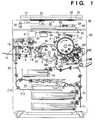
- Fig. 1 is a sectional view of a color image processing apparatus of this embodiment.
- the color image processing apparatus of this embodiment has a digital color image reader unit (to be referred to as a reader unit hereinafter) 50 in its upper portion, and a digital color image printer unit (to be referred to as a printer unit hereinafter) 60 in its lower portion.
- a digital color image reader unit to be referred to as a reader unit hereinafter
- a digital color image printer unit to be referred to as a printer unit hereinafter
- an original 30 is placed on an original glass plate 31, and is exposed and scanned by an exposure lamp 32.
- An optical image defined by light reflected by the original 30 is formed on a full-color sensor 34 by a lens 33 via mirrors 35 and 36, thus obtaining color-separated image signals.
- the color-separated image signals obtained by the full color sensor (comprising, e.g., a CCD; to be referred to as a CCD hereinafter) 34 are subjected to various image processing operations in an image processing unit 40 (to be described later) via an amplifier (not shown), and the processed signals are output to the printer unit 60.
- reference numeral 37 denotes a standard white plate, and a detailed description thereof will be given later.
- a photosensitive drum 1 as an image carrier is carried to be rotatable in the direction of an arrow in Fig. 1.
- a pre-exposure lamp 11, a corona charger 2, a laser exposure optical system (3a, 3b, and 3c), a potential sensor 12, four developers 4Y, 4C, 4M, and 4K of different colors, a drum light amount detector 13, a transfer drum 5, and a cleaning device 6 are arranged around the photosensitive drum 1.
- Each of the image signals obtained by the reader unit 50 is converted into an optical signal by a laser output unit 41.
- a laser beam output from a laser 42 is reflected by a polygonal mirror 3a, and is projected as an optical image 43 onto the surface of the photosensitive drum 1 via a lens 3b and a mirror 3c.
- the photosensitive drum 1 is rotated in the direction of the arrow in Fig. 1, the photosensitive drum 1, which has been discharged by the pre-exposure lamp 11, is uniformly charged by the charger 2, and an optical image 43 for each separated color is irradiated onto the drum surface, thus forming a latent image.
- the developer of a predetermined color is operated to develop the latent image on the photosensitive drum 1, thereby forming a resin-based toner image on the photosensitive drum 1.
- the developers alternatively approach the photosensitive drum 1 upon operation of eccentric cams 24Y, 24C, 24M, and 24K.
- the toner image on the photosensitive drum 1 is transferred onto a recording medium, which is fed from a recording medium cassette 7a, 7b, or 7c to a position opposing the photosensitive drum 1 via a convey system and the transfer drum 5.
- the transfer drum 5 is rotatably supported, and a recording medium carrier sheet cylindrically and integrally extends on the circumferential opening of the drum 5.
- a desired number of color images (toner images) on the photosensitive drum 1 are transferred on the recording medium carried on the recording medium carrier sheet by a charger and rollers (neither are shown), thus forming a full-color image.
- the recording medium is peeled from the transfer drum 5 upon operation of a peeling pawl 8a, a peeling push-up roller 8b, and a peeling charger 8c, and is discharged onto a tray 10 via a heat roller fixing device 9.
- the residual toner on the surface of the photosensitive drum 1 is cleaned by the cleaning device 6, and the drum 1 is subjected to the next image forming process.
- a convey path switching guide 19 is driven immediately after the recording medium exits the fixing device 9, and is temporarily guided to a reversal path 21a via a vertical convey path 20. Thereafter, upon rotating reversal rollers 21b in the opposite direction, the recording medium leaves the path with the trailing end, when it is fed into the path, leading, i.e., in a direction opposite to the feed direction, and is stored in an intermediate tray 22. Thereafter, an image is formed on the other surface of the recording medium by executing the above-mentioned image forming processing again.
- the transfer drum 5 is cleaned upon operation of a fur brush 14 and a backup brush 15 which opposes the brush 14 via the recording medium carrier sheet, or upon operation of an oil removal roller 16 and a backup brush 17 which opposes the roller 16 via the recording medium carrier sheet.
- This cleaning operation is performed before or after image formation, and is performed as needed when a jam (paper jam) has occurred.
- Reference numeral 39 denotes an image leading end sensor.
- signal plates 38a and 38b cross the sensor 39, an image leading end signal ITOP is generated.
- the plate 38a and 38b are located at opposing angular positions separated by 180°, and two signals ITOP are generated per revolution of the transfer drum 5.
- the image processing unit 40 shown in Fig. 1 will be described in detail below with reference to Fig. 2.
- Fig. 2 is a block diagram showing the detailed arrangement of the image processing unit 40 shown in Fig. 1.
- Image signals photoelectrically converted by the CCD 34 in Fig. 1 are subjected to gain control and offset adjustment in a CCD processor 201, and are converted by an A/D converter (not shown) into 8-bit digital image signals R, G, and B in units of color signals.
- the CCD processor 201 will be simply referred to as a CCD 201.
- the image signals are input to a shading correction unit 202, and are subjected to known shading correction in units of colors using a signal obtained by reading the standard white plate 37 shown in Fig. 1.
- any spatial deviation, in the sub-scanning direction, of the image signals is corrected by a sub-scanning synchronization processor 203 comprising a line delay element.
- Reference numeral 204 denotes an input masking unit, which corrects variations in R, G, and B filters of the CCD 34.
- Reference numeral 205 denotes a light amount/density converter, which comprises a look-up table ROM (or RAM), and converts luminance signals R, G, and B into density signals C, M, and Y.
- Reference numeral 206 denotes a known masking & UCR unit, which selects one of output signals Y, M, C, and Bk as a signal V1 from the input three primary signals Y, M, and C, and sequentially outputs the signal V1 of a predetermined bit length (e.g., 8 bits) in each reading operation. The detailed description of the unit 206 will be omitted.
- Reference numeral 207 denotes a selector for selecting an image signal to be recorded.
- the selector 207 selects one of the CCD reading image signal V1 and an image signal V2 from an external apparatus 219 (to be described later) at an arbitrary timing in accordance with a signal from a CPU 217.
- Reference numeral 208 denotes a known gamma correction unit for attaining image recording with a desired density/gradation in correspondence with the characteristics of the printer.
- Reference numeral 209 denotes a laser driver, which converts each digital image signal into, e.g., a pulse-modulated analog signal, and drives the laser output unit 41 shown in Fig. 1.
- Reference numeral 217 denotes a CPU, which drives a motor 221 for reciprocally moving an optical system, constituted by the lamp 32 and the mirrors 35 and 36 shown in Fig. 1, via a motor driver 216.
- the CPU 217 performs light amount control and ON/OFF control of the exposure lamp 32 via a CVR (Constant Voltage Regulator; lamp regulator) 214, and also controls an operation panel 213 via an I/O unit 212.
- the CPU includes known devices such as a RAM, ROM, and the like.
- a communication controller 211 controls communications with the motor driver 216 and an external apparatus 219.
- the communications with the external apparatus 219 include reception of information such as a paper size and color mode upon recording of an image signal, and a recording start/end command, and transmission of status data of the reader unit 50 and the printer unit 60 to the external apparatus 219.
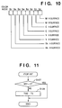
- Reference numeral 210 denotes a synchronization signal generator, which generates clocks CLK1 in units of pixels, line synchronization signals HSYNC1 and HSYNC2, and synchronization signals PSYNC1 and PSYNC2 in units of pages on the basis of the signals ITOP generated in synchronism with the rotation of the transfer drum 5 and a signal BD generated in synchronism with the rotation of a polygonal mirror.
- Reference numeral 220 denotes a speed converter for converting an image signal V2' which is supplied from the external apparatus 219 in synchronism with pixel clocks CLK2 and an image effective period signal LE for one line into an image signal V2 which is synchronized with the internal pixel clocks CLK1 and the line synchronization signal HSYNC1.
- a counter 215 has three counters for counting clocks CPU-CLK from the CPU 217 by predetermined counts, and generates interrupt signals TM1-INT, TM2-INT, and TM3-INT to be supplied to the CPU 217 and the motor driver 216. These signals will be described in detail later.
- Figs. 3A and 3B show the relationship between the signal ITOP output from the image leading end sensor 39 shown in Fig. 1 and an image.
- the end of the recording medium is clamped by grippers arranged on the transfer drum 5, thereby fixing the recording medium.
- the relationship between the signal ITOP and an image is as shown in Fig. 3A.
- one period of the signal ITOP represents one circumference of the transfer drum in a conventional image processing apparatus.
- Fig. 4 shows the conventional relationship between the signals ITOP and image forming operations from a plurality of image sources in the above-mentioned two-sheet attraction function.
- a recording operation of an image read from the CCD 201 upon operation of the operation panel 213 will be referred to as a copy or local copy operation hereinafter
- a recording operation of an image input from the external apparatus 219 will be referred to as a print or remote print operation hereinafter.
- Fig. 4 shows an example wherein a remote print request is issued during the recording operation for a local copy request of three pages.
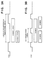
- Fig. 5A is a block diagram showing the detailed structure of the synchronization signal generator 210.
- the signal ITOP which is generated in synchronism with the rotation of the transfer drum 5 is synchronized with the line synchronization signal HSYNC1 by a latch 51, thus generating a signal PSYNC0.
- the signal PSYNC0 is input to AND gates 52 and 53 to be locally ANDed to two enable signals ENB1 and ENB2 supplied from the CPU 217, respectively, thus generating signals PSYNC1 and PSYNC2.
- the page synchronization signal PSYNC1 is used for an image from the CCD 201, i.e., the local copy operation, and the page synchronization signal PSYNC2 is used for recording of an image from the external apparatus 219, i.e., the remote print operation.
- Fig. 5B is a timing chart of the signals shown in Fig. 5A.
- the enable signals ENB1 and ENB2 supplied from the CPU 217 serve as gate signals of the signal PSYNC0, and are turned on or off after an elapse of a time T3 from the leading edge of the signal ITOP.
- the time T3 is equal to or longer than an AND period T2 of the signals ITOP and PSYNC0, and is equal to or shorter than an ITOP period time T1.
- the time T3 is measured by a timer TM2 arranged in the counter 215 shown in Fig. 2 from the leading edge of the signal ITOP, and is assured by an interrupt signal TM2-INT to the CPU 217.
- the CPU can control the signals ENB1 and ENB2 to arbitrarily obtain four different combinations of ON/OFF states of the signals PSYNC1 and PSYNC2, i.e., four states (1), (2), (3), and (4) shown in Fig. 5B.
- state (1) represents a state wherein both the signals PSYNC1 and PSYNC2 are at L level
- state (2) represents a state wherein the signal PSYNC1 is at H level and the signal PSYNC2 is at L level
- state (3) represents a state wherein the signal PSYNC1 is at L level and the signal PSYNC2 is at H level
- state (4) represents a state wherein both the signals PSYNC1 and PSYNC2 are at H level.
- Fig. 6 particularly shows the driving sequence of the motor 221 for scanning the optical system constituted by the exposure lamp 32 and the mirrors 35 and 36, and the ON/OFF control sequence of the exposure lamp 32.
- Fig. 6 is a timing chart showing the control operations of the exposure lamp 32 and the motor 221.
- a timer TM3 arranged in the counter 215 starts measurement ((b)).
- the timer TM3 After measurement of a time T4 ((c)), the timer TM3 generates an interrupt signal TM3-INT ((d)), and supplies it to the motor driver 216.
- the motor 221 rises at a predetermined acceleration ((e)
- the optical system rises at a predetermined acceleration.
- the optical system moves forward at a low speed.
- the optical system After the optical system scans a predetermined distance, it decelerates at the same rate as that upon rising ((f)), and stops. Thereafter, the optical system starts backward movement, and stops at a forward movement start position ((g)) to wait for the interrupt signal TM3-INT for the next scan. Also, the exposure lamp 32 is turned on in synchronism with the interrupt signal TM3-INT ((h)).
- the trailing edge (i) of the signal PSYNC1 is used as an interrupt signal PSYNC-INT to the CPU, as shown in Fig. 2, and image formation based on an image signal V1 is started in synchronism with the trailing edge of the signal PSYNC1 ((j)). Furthermore, an image period time T5 from the generation timing of the signal PSYNC-INT is measured by a timer TM1 arranged in the counter 215 shown in Fig. 2 ((k)). Upon completion of measurement of T5 ((l)), in response to the leading edge (m) of an interrupt signal TM1-INT, image formation is completed in a desired duration ((n)) and the exposure lamp 32 is turned off ((o)).
- Fig. 7 is a timing chart showing the relationship between the page synchronization signal PSYNC2 and image formation in the remote print operation. Since an image from the external apparatus 219 is formed regardless of the acceleration time of the motor 221 and the rise time of the exposure lamp 32, the remote print operation is performed using only the timer TM1.
- the interrupt signal PSYNC-INT is generated at the trailing edge (a) of the signal PSYNC2, and image formation based on an image signal V2 is started in synchronism with the interrupt signal PSYNC-INT ((b)).
- the timer TM1 arranged in the counter 215 measures an image period time T5 from the generation timing of the interrupt signal PSYNC-INT ((c)). Upon completion of measurement of T5 ((d)), in response to the leading edge of the interrupt signal TM1-INT ((e)), image formation is completed in a desired duration ((f)).
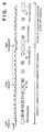
- Fig. 8 is a timing chart of the signals upon simultaneous execution of the local copy operation and the remote print operation. The sequence upon reception of a remote print request of three pages during local copy processing of three pages will be described below. Note that various flags are used for controlling the sequences in this embodiment, and Fig. 8 also shows the transition states of flags (to be described in detail later).
- the first and second images V1 and V2 are alternately transferred onto the recording media, which are two-sheet-attached to the transfer drum 5, in units of colors in synchronism with the page synchronization signals PSYNC1 for local copy and the page synchronization signals PSYNC2 for remote print, respectively.
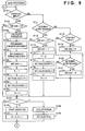
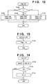
- Fig. 9 is a flow chart showing the main sequence control upon execution of the local copy operation and the remote print operation in this embodiment. This control will be described below.
- step S101 in Fig. 9 the presence/absence of input of the start key on the operation panel 213 is checked. If YES in step S101, the flow advances to step S102 to check if the 0th bit of a flag MD on the RAM is "0" to discriminate if the local copy or remote print operation is selected. If YES in step S102, various parameters for the operation are calculated in step S103, and the optical system is preliminarily moved forward to the original scan start position in step S104. In step S105, a scanning period and speed are set in the motor driver 216. In step S106, the 0th bit of the flag MD is set to be "1".
- step S107 a flag F on the RAM, which flag is used for discriminating an image source to be subjected to next recording, is set to be "01H". Note that "01H” in hexadecimal notation represents "01".
- the flow then advances to step S108 to set a recording page count in an area P1 on the RAM.
- step S109 a color mode is set in an area C1 on the RAM.
- step S110 an area Q1 on the RAM, which area stores a recorded page count, is cleared to "0". Thereafter, the flow advances to step S122.
- Fig. 10 shows in detail the color mode C1 set in step S109.
- the color mode has an 8-bit configuration
- the 0th and 1st bits (b0, b1) correspond to magenta
- the 2nd and 3rd bits (b2, b3) correspond to cyan
- the 4th and 5th bits (b4, b5) correspond to yellow
- the 6th and 7th bits (b6, b7) correspond to black.
- the 0th, 2nd, 4th, and 6th bits correspond to the A surface in the case of "two-sheet attachment”
- the 1st, 3rd, 5th, and 7th bits correspond to the B surface.
- step S111 the presence/absence of a remote print start request from the external apparatus 219 is checked. If YES in step S111, it is checked in step S112 if the 1st bit of the flag MD is "0". If YES in step S112, the 1st bit of the flag MD is set to be "1" in step S113, and the above-mentioned flag F is set to be "02H” in step S114.
- step S115 to set a recording page count in an area P2 on the RAM.
- step S116 a color mode is set in an area C2 on the RAM.
- step S117 an area Q2 on the RAM, which area stores a recorded page count, is cleared to "0". Thereafter, the flow advances to step S122. Note that the flag C2 representing the color mode is the same as C1 described above.
- the 0th bit of the flag MD means a local copy request, and its 1st bit means a remote print request. While “1" is set in each bit, it indicates that the corresponding recording operation is requested and is not completed yet. If the flag F is "01H”, an input image from the CCD 201 is subjected to the next recording; if the flag F is "02H", an image input from the external apparatus 219 is subjected to the next recording.
- step S111 If it is determined in step S111 that a remote print request is not detected, the flow advances to step S118 to check the presence/absence of input of the stop key on the operation panel 213. If YES in step S118, the flow advances to step S119 to set the 0th bit of the flag MD to be "0", and the flow advances to step S122. That is, the local copy processing is cleared. On the other hand, if NO in step S118, the flow advances to step S120 to check if a print stop request is issued from the external apparatus 219. If YES in step S120, the 1st bit of the flag MD is set to be "0" in step S121, and the flow advances to step S122. That is, the remote print processing is cleared. However, if NO in step S120, the flow advances to step S122.
- step S102 determines whether the 0th bit of the flag MD is not "0" or if it is determined in step S112 that the 1st bit of the flag MD is not "0"
- the flow also advances to step S122.
- step S122 a flag D on the RAM, which flag is cleared to "0" in initialization and represents the current recording operation status, is checked. If the flag D is "0", since it is determined that a recording operation is not being executed currently, a recording operation is started in step S123. In step S124, the flag D is set to be "1" and a color mode flag B on the RAM, which flag indicates the developing color, is set to be "1". Thereafter, the flow returns to step S101. Note that the color mode flag B has the same bit configuration as those of the color mode flags C1 and C2, but only one of 8 bits is always "1".
- step S122 determines whether the flag D is "1" since a recording operation is being executed currently. If it is determined in step S122 that the flag D is "2”, since it indicates the end of a recording operation, the color mode flag B and the flag D are cleared to "0" in step S126, and the flow returns to step S101.
- Fig. 11 is a flow chart of the interrupt processing to the CPU 217 by a signal ITOP-INT which is simultaneously generated in response to the leading edge of the signal ITOP.
- step S127 it is checked if the value of the flag MD is "00H", i.e., if both the 0th and 1st bits of the flag MD are "0". If NO in step S127, the flow advances to step S128 to set the above-mentioned time T3 in the timer TM2 used for generating the enable signals ENB1 and ENB2, thereby starting measurement.
- Fig. 12 is a flow chart showing the interrupt processing by the interrupt signal TM2-INT.
- step S129 the flag F indicating an image source is checked in step S129. If it is determined in step S129 that the flag F is "01H", since the selected processing is local copy processing, the flow advances to step S130 to turn on the enable signal ENB1 and to turn off the enable signal ENB2. If it is determined in step S129 that the flag F is "02H", since the selected processing is remote print processing, the enable signal ENB1 is turned off and the enable signal ENB2 are turned on in step S132. If it is determined in step S129 that the flag F is "00H”, since the recording operations from all image sources have been finished, both the enable signals ENB1 and ENB2 are turned off in step S131.
- step S152 the above-mentioned time T4 is set in the above-mentioned timer TM3 to generate the driving start timing of the motor 221 for driving the optical system, and the measurement of T4 is started.
- step S154 the value of the flag MD is checked. If the value of the flag MD is "00H”, since a recording operation need not be performed, the flag D is set to be "2" to indicate the end of operation in step S155. On the other hand, if it is determined in step S154 that the value of the flag MD is not "00H", the interrupt processing ends.
- the signal PSYNC-INT indicates detection of the leading end of an image.
- step S133 the above-mentioned image period time T5 is set in the above-mentioned timer TM1 for counting the trailing end of an image.
- step S134 the flag F indicating an image source is checked. If it is determined in step S134 that the flag F is "01H" or "02H", since there is a possibility of image recording, the flow advances to step S135.
- an image source indicated by each flag is indicated. For example, "C F " represents the flags C1 and C2, C1 indicates local copy, and C2 indicates remote print.
- step S135 the AND of the color mode flag C F indicating set colors and the color mode flag B indicating the developing color is calculated. More specifically, if the flag F is "01H”, the AND of the color mode flag C1 and the color mode flag B is calculated; if the flag F is "02H”, the AND of the color mode flag C2 and the color mode flag B is calculated. If the AND calculated in step S135 is not "00H", since the image recording timing has been reached, VF is permitted in step S136. More specifically, if the flag F is "01H”, V1 is permitted; if the flag F is "02H", V2 is permitted. In step S137, an image is recorded in the developing color indicated by the color mode flag B, and the flow advances to step S138.
- step S134 determines whether the flag F is "00H"
- step S135 determines whether the AND of the color mode flag C F and the color mode flag B is "00H”
- step S138 the color mode flag B is checked. If the color mode flag B is "01H” or "02H", since it indicates magenta recording on the A or B surface, i.e., recording of the first color, the flow advances to step S139, and the recorded page count Q F is incremented by 1. As a result of increment in step S139, if it is determined in step S140 that the recorded page count Q F is equal to the recording page count P F , the number of remaining pages to be recorded is 1, and the flow advances to step S141. In step S141, the color mode flag B is checked. If the color mode flag B is "01H”, the flow advances to step S142 to set the color mode C F to be "55H", i.e., to perform recording of only the A surface. Thereafter, the flow advances to step S146.
- step S141 if it is determined in step S141 that the flag B is "02H", since it indicates magenta recording on the B surface, the flow advances to step S160 to check if the flag MD is "03H", i.e., if both the 0th and 1st bits of the flag MD are "1" and a local copy request and a remote print request are simultaneously generated. If YES in step S160, the flow advances to step S143 to set the color mode C F to be executed to be "AAH", i.e., to perform recording of only the B surface. Thereafter, the flow advances to step S146.
- step S140 determines whether the recorded page count Q F is not equal to the recording page count P F , since the number of remaining pages to be recorded is 2 or more, the color mode need not be changed, and hence, the flow jumps to step S146. If it is determined in step S160 that the flag MD is not "03H", since the local copy processing and the remote print processing are simultaneously requested, the flow jumps to step S146 without changing the color mode flag C F , though it indicates recording of the B surface.
- step S144 the recorded page count Q F is compared with the recording page count P F . If these two values are equal to each other, since it means the end of recording, the flow advances to step S145 to set the (F-1)-th bit of the flag MD, i.e., the 0th or 1st bit, to be "0". Thereafter, the flow advances to step S146. On the other hand, if it is determined in step S144 that the recorded page count Q F is not equal to the recording page count P F , the flow jumps to step S146.
- step S146 it is checked if the color mode flag B is "80H". If YES in step S146, the flow advances to step S148 to update the color mode flag B to be "01H”. On the other hand, if NO in step S146, the flow advances to step S147 to double the color mode flag B. More specifically, the value set for recording of the A surface of the color mode flag B is updated to that for recording of the B surface, or the value set for recording of the B surface is updated to that for recording of the A surface of the next color.
- step S149 determines whether the flag MD is "03H”
- the flow advances to step S151 to update the flag F to the value of the flag MD. More specifically, if the flag MD is "01H” or "02H", since a request from only one image source is generated, the value of the flag F is set to be the same as that of flag MD.
- the color mode is set based on the respective flags.
- the local copy processing is performed when the flag F is "1”
- the remote print processing is performed when the flag F is "2".
- the flag value of each processing may replace each other.
- the image processing apparatus of this embodiment must clearly inform the current operation status to an operator since it operates based on requests from various image sources.
- Fig. 16 shows display examples on a character display unit (LCD, CRT, or the like) of the operation panel 213.
- the operation panel 213 of this embodiment has input means such as the known start key, stop key, ten-key pad, and the like, and display means such as a LCD, LED, and the like other than that shown in Fig. 16, as a matter of course, but a detailed description thereof will be omitted.
- the respective operation panel states shown in Fig. 16 correspond to the sequence shown in the timing chart in Fig. 8, and a local copy operation of three pages and a remote print operation of three pages are performed.
- a display a in Fig. 16 is made on the operation panel 213.
- a message indicating that a local copy operation is being executed, and a message indicating that a remote print operation can be performed are displayed.
- the set page count and the recorded page count of the local copy operation are displayed. Alternatively, the number of remaining pages to be recorded may be displayed.
- a display b shown in Fig. 16 is made, and the recorded page count is updated.
- a remote print request is issued, the remote print processing is started, and a display c shown in Fig. 16 is made.
- a message indicating that a remote print operation is being executed is displayed, and the set page counts and the recorded page counts of the local copy and remote print operations are displayed.
- a message indicating that a remote print operation is being executed, and a message indicating that a local copy operation can be performed are displayed, as shown in a display state e in Fig. 16.
- a display state e in Fig. 16 With this display, an operator can know that a local copy operation can be executed even when the image processing apparatus of this embodiment is in operation. Even when the paper size of the local copy or remote print operation is A3 or the like, and "two-sheet attachment" processing is not available, since the set page count and the recorded page count of the remote print operation are displayed, an operator can predict the wait time until the local copy processing is started.
- a message indicating that the image processing apparatus is in a standby state is displayed, as shown in a display state f in Fig. 16.
- the current developing color (M, C, Y, Bk) can also be displayed, and it can serve as a measure for an operator upon prediction of the wait time.
- the present invention is applied to a case wherein the above-mentioned first embodiment is further developed.
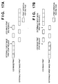
- Fig. 17A illustrates the timings in the local copy and remote print operations in the above-mentioned first embodiment.
- Fig. 17A shows a state wherein the print operation of an image from the CCD 201 in the first embodiment, i.e., the local copy operation is executed first, and the print operation of an image input from the external apparatus 219, i.e., the remote print operation is started during the local copy operation.
- a case opposite to Fig. 17A can be processed based on the same principle as in the first embodiment described above. That is, the present invention is applicable to a case wherein the remote print operation from the external apparatus 219 is executed first, and the local copy operation from the CCD 201 is started during the remote print operation, as shown in Fig. 17B.
- the preceding operation ends first.
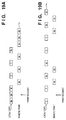
- the present invention is also applicable to a case wherein an operation started later ends during the preceding operation, as shown in Figs. 18A and 18B.
- Fig. 18A shows a case wherein the remote print operation is started and ends during the local copy processing, and the local copy processing is subsequently executed.
- Fig. 18B shows a case wherein the local copy operation is started and ends during the remote print processing, and the remote print processing is subsequently executed, contrary to the case shown in Fig. 18A.
- full-color images from different image sources are recorded.
- the present invention is not limited to a full-color image as an object to be recorded.
- the present invention is also applicable to a case wherein one of two images to be recorded is other than a full-color image, e.g., a monochrome image, as shown in Figs. 19A and 19B.
- Figs. 19A and 19B show processing executed when a full-color image is to be recorded by the local copy processing, and a monochrome black image is to be recorded by the remote print processing.
- Fig. 19A shows a case wherein Bk recording of the remote print processing is executed between each two adjacent ones of M, C, Y, and Bk recording operations of the local copy processing, and the developing color is switched every half revolution of the transfer drum.
- Fig. 19B shows a case wherein the remote print processing of Bk is performed only when Bk development is performed in the local copy processing.
- the remote print processing of Bk may be performed immediately after execution of Bk development in the local copy processing like a print operation indicated by a solid frame in Fig. 19B, or immediately before execution of Bk development in the local copy processing like a print operation indicated by a dotted frame, or both of these operations may be used.
- Such an operation mode may be selected in correspondence with the switching time performance of the developing color.
- the local copy processing and remote print processing may replace each other.
- the execution speed of the remote print processing is lower than that in Fig. 19A.
- the processing speed of the local copy processing can be higher than that in Fig. 19A since the developing color need not be switched for each development.
- the remote print processing can be executed anytime during execution of the local copy processing, and vice versa.
- Fig. 20 is a flow chart showing parallel processing in the third embodiment.
- the processing shown in Fig. 20 is a portion for discriminating whether or not each interrupt processing request is executed, and corresponds to processing portions in steps S101, S102, S111, and S112 shown in Fig. 9 of the first embodiment described above. Since other processing operations are the same as those in Fig. 9 above, a detailed description thereof will be omitted.
- step S1400 the presence/absence of a local copy request is checked. If YES in step S1400, the flow advances to step S1401 to check if the local copy processing has already been started. If NO in step S1401, the flow advances to step S1402 to check if the remote print processing has already been started. If NO in step S1402, the flow advances to step S1404 to execute the local copy processing; otherwise, the flow advances to step S1403 to compare the priority level of the remote print processing in execution with that of the latest local copy request. If it is determined in step S1403 that the priority level of the local copy request is higher than that of the remote print processing, the flow advances to step S1404 to execute the local copy processing; otherwise, the flow returns to step S1400.
- step S1400 If it is determined in step S1400 that a local copy request is not detected, the flow advances to step S1405 to check the presence/absence of a remote print request. If YES in step S1405, the flow advances to step S1406 to check if the remote print processing has already been started. If NO in step S1406, the flow advances to step S1407 to check if the local copy processing has already been started. If NO in step S1407, the flow advances to step S1409 to start the remote print processing; otherwise, the flow advances to step S1408 to compare the priority level of the local copy processing in execution with that of the latest remote print request. If it is determined in step S1408 that the priority level of the remote print request is higher than that of the local copy processing, the flow advances to step S1409 to execute the remote print processing; otherwise, the flow returns to step S1400.
- the priority levels of the local copy and remote print operations may be stored in advance in an internal ROM of the image processing apparatus of the third embodiment or the external apparatus 219, or may be stored in a RAM, so that the priority levels can be changed as needed.
- priority levels are assigned to the local copy processing and the remote print processing, and an image output operation is executed with reference to the priority levels, thus providing an image processing apparatus with higher operability.
- Fig. 21 is a view showing priority discrimination processing in a communication protocol between the external apparatus 219 and the color image processing apparatus.
- the external apparatus 219 sends a status request command to the image processing apparatus, and receives, as status data, information which indicates whether or not the apparatus is in operation, the presence/absence of abnormality and the details of the abnormality if present, the preset paper sheet sizes, and the like.
- the external apparatus 219 sends a print request command to the image processing apparatus together with information necessary for the print processing such as a print page count, paper size, color mode, and the like.
- the image processing apparatus When the image processing apparatus, which received the print request command, does not execute local copy processing, it sends back, using ACK status, a message indicating reception of the request to the external apparatus 219, and starts print processing. On the other hand, when the image processing apparatus is executing the local copy processing, it inquires the priority of the print processing to the external apparatus 219. The external apparatus 219 checks if the print processing is given priority. If the print processing is not given priority, the external apparatus 219 temporarily halts printing, and waits until the image processing apparatus is ready. If the external apparatus 219 has priority, it issues a priority print request command to the image processing apparatus, and upon reception of this command, the image processing apparatus preferentially executes the print processing from the external apparatus 219.
- the image processing apparatus of the third embodiment is arranged not to execute print processing when it receives a priority print request command from the external apparatus 219 before receiving a normal print request therefrom, thereby preventing meaningless priority discrimination by frequent priority print request commands indiscriminately issued by the external apparatus 219.
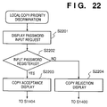
- Fig. 22 is a flow chart showing an example of security checking using a password.
- step S2201 in Fig. 22 a message for urging an operator to input a password such as "input password” is displayed on the operation panel 213 to request an operator to input a password.
- the flow advances to step S2202 to check if the input password coincides with a specific password which is registered in advance in, e.g., a nonvolatile memory such as a ROM in the CPU 217. If it is determined in step S2202 that the input password is registered, the flow advances to step S2203 to display a message indicating acceptance of the local copy request such as "copy is accepted", and the copy processing in step S1404 shown in Fig. 20 above is started.
- step S2202 determines whether the input password does not coincide with the registered password. If it is determined in step S2202 that the input password does not coincide with the registered password, the flow advances to step S2204, and a message indicating that the local copy request is rejected such as "copy is rejected due to non-coincidence of password; please wait for end of print" is displayed. Thereafter, the copy request discrimination processing in step S1400 shown in Fig. 20 above is started.
- the priority discrimination processing based on a password is performed in step S1403 shown in Fig. 20, and the priority discrimination processing based on the presence/absence of priority is performed in step S1408.
- the present invention is not limited to this.
- the priority discrimination processing based on the presence/absence of priority may be performed in step S1403, and the priority discrimination processing based on a password may be performed in step S1408.
- the local copy and remote print operations can be processed in correspondence with the priority levels.
- security control can be realized by setting a password, the image processing apparatus with higher operability can be provided.
- the CCD 34 for reading an original image, and the external apparatus 219 such as a computer have been exemplified as a plurality of image sources.
- the present invention is not limited to these, but may be applied to images input from any other image processing apparatuses such as a computer, facsimile apparatus, optical disk/magnetic disk, and the like.
- the number of image sources can be increased to three or more based on the same principle as the present invention. However, in this case, since a maximum of two recording media can only be attracted on the transfer drum, an image source to be subjected to recording can be arbitrarily determined according to the apparatus characteristics or as an operator demands.
- an image from the external apparatus is received as image information which is converted into that in a color space of developing colors M, C, Y, and Bk.
- image information from the external apparatus may be received as information in an color space between the input masking unit 204 and the light amount/density converter 205, or information in other color spaces may be used.
- images input from a plurality of image sources are alternately output onto recording media.
- the present invention is not limited to this.
- these images may be output to image output means other than recording media such as a storage device.
- images from a plurality of image sources can be efficiently processed without limiting image generating apparatuses or without limiting the formats of input images.
- the present invention may be applied to either a system constituted by a plurality of devices or an apparatus consisting of a single device.
- the present invention is also applicable to a case wherein the invention is achieved by supplying a program to a system or apparatus.
- an image processing apparatus of this invention can record images input from a plurality of image sources on a plurality of recording media simultaneously held on a recording medium holding member, the images input from the plurality of image sources can be efficiently output, and the productivity of the image processing apparatus can be improved.
Landscapes
- Engineering & Computer Science (AREA)
- Multimedia (AREA)
- Signal Processing (AREA)
- Computer Hardware Design (AREA)
- Microelectronics & Electronic Packaging (AREA)
- Color Electrophotography (AREA)
- Color, Gradation (AREA)
- Color Image Communication Systems (AREA)
Applications Claiming Priority (2)
| Application Number | Priority Date | Filing Date | Title |
|---|---|---|---|
| JP6058633A JP2918784B2 (ja) | 1994-03-29 | 1994-03-29 | 画像処理装置及び方法 |
| JP58633/94 | 1994-03-29 |
Publications (3)
| Publication Number | Publication Date |
|---|---|
| EP0675633A2 true EP0675633A2 (de) | 1995-10-04 |
| EP0675633A3 EP0675633A3 (de) | 1996-01-10 |
| EP0675633B1 EP0675633B1 (de) | 1999-03-03 |
Family
ID=13089995
Family Applications (1)
| Application Number | Title | Priority Date | Filing Date |
|---|---|---|---|
| EP95104549A Expired - Lifetime EP0675633B1 (de) | 1994-03-29 | 1995-03-28 | Bildverarbeitungsgerät und -verfahren |
Country Status (4)
| Country | Link |
|---|---|
| US (1) | US5883724A (de) |
| EP (1) | EP0675633B1 (de) |
| JP (1) | JP2918784B2 (de) |
| DE (1) | DE69507974T2 (de) |
Families Citing this family (11)
| Publication number | Priority date | Publication date | Assignee | Title |
|---|---|---|---|---|
| US6977752B1 (en) * | 1995-08-07 | 2005-12-20 | Electronics For Imaging, Inc. | Method and apparatus for determining toner level in electrophotographic print engines |
| US6657741B1 (en) * | 1995-08-07 | 2003-12-02 | Tr Systems, Inc. | Multiple print engine system with selectively distributed ripped pages |
| US7046391B1 (en) * | 1995-08-07 | 2006-05-16 | Electronics For Imaging, Inc. | Method and apparatus for providing a color-balanced multiple print engine |
| US6449051B2 (en) * | 1998-03-30 | 2002-09-10 | Minolta Co., Ltd. | Image producing apparatus having a function to control document data |
| JP3542304B2 (ja) * | 1999-06-16 | 2004-07-14 | シャープ株式会社 | 印刷装置及びホスト装置 |
| USD457833S1 (en) | 2001-05-24 | 2002-05-28 | Fernando U. Juan | Pattern for forming polygon |
| US7723083B2 (en) * | 2005-12-13 | 2010-05-25 | E.I. Du Pont De Nemours And Company | Production of peracids using an enzyme having perhydrolysis activity |
| US8305609B2 (en) * | 2008-05-07 | 2012-11-06 | International Business Machines Corporation | Prioritizing print requests for a configurable shared network printer |
| JP6330505B2 (ja) * | 2014-06-18 | 2018-05-30 | ブラザー工業株式会社 | 画像読取装置 |
| JP6330506B2 (ja) | 2014-06-18 | 2018-05-30 | ブラザー工業株式会社 | 画像読取装置 |
| JP6265873B2 (ja) * | 2014-09-24 | 2018-01-24 | キヤノン株式会社 | モバイル端末とその制御方法、及びプログラム |
Family Cites Families (15)
| Publication number | Priority date | Publication date | Assignee | Title |
|---|---|---|---|---|
| US3909818A (en) * | 1973-09-14 | 1975-09-30 | Metrodata Corp | Multiple channel alphanumeric residential television video signal generator |
| US4236813A (en) * | 1976-08-27 | 1980-12-02 | Levine Alfred B | Multiplex photocopier system having plural scanners without memory |
| JPH0677173B2 (ja) * | 1982-11-10 | 1994-09-28 | キヤノン株式会社 | 像形成装置 |
| JPS611164A (ja) * | 1984-06-14 | 1986-01-07 | Toshiba Corp | 画像形成装置 |
| US5040031A (en) * | 1986-05-10 | 1991-08-13 | Canon Kabushiki Kaisha | Image processing apparatus which can control output to multiple devices to accommodate differing operating timing of those devices |
| EP0369429B1 (de) * | 1988-11-16 | 1994-09-14 | Canon Kabushiki Kaisha | Aufnahmegerät mit mehreren Entwicklungseinheiten |
| US4941170A (en) * | 1989-03-20 | 1990-07-10 | Tandem Computers Incorporated | Facsimile transmissions system |
| US5410642A (en) * | 1989-08-23 | 1995-04-25 | Dai Nippon Printing Co., Ltd. | ID card issuing system |
| JP2910116B2 (ja) * | 1990-01-25 | 1999-06-23 | ブラザー工業株式会社 | インターフェース付ファクシミリ装置 |
| US5548789A (en) * | 1991-01-24 | 1996-08-20 | Canon Kabushiki Kaisha | Message communication processing apparatus for selectively converting storing and transmitting messages of different lengths |
| JP3088769B2 (ja) * | 1991-04-18 | 2000-09-18 | 株式会社リコー | 画像形成装置 |
| WO1993009501A1 (en) * | 1991-11-01 | 1993-05-13 | Yeh Keming W | Portable device having data storage capability for transferring data between a portable computer and a desktop computer |
| JP2710195B2 (ja) * | 1992-12-15 | 1998-02-10 | インターナショナル・ビジネス・マシーンズ・コーポレイション | 記憶装置コントローラ |
| JPH06319003A (ja) * | 1993-02-22 | 1994-11-15 | Canon Inc | 画像処理装置 |
| US5528374A (en) * | 1993-11-22 | 1996-06-18 | Eastman Kodak Company | Networked reproduction apparatus with security feature |
-
1994
- 1994-03-29 JP JP6058633A patent/JP2918784B2/ja not_active Expired - Fee Related
-
1995
- 1995-03-28 EP EP95104549A patent/EP0675633B1/de not_active Expired - Lifetime
- 1995-03-28 DE DE69507974T patent/DE69507974T2/de not_active Expired - Fee Related
-
1997
- 1997-01-22 US US08/785,968 patent/US5883724A/en not_active Expired - Lifetime
Also Published As
| Publication number | Publication date |
|---|---|
| JP2918784B2 (ja) | 1999-07-12 |
| EP0675633A3 (de) | 1996-01-10 |
| DE69507974D1 (de) | 1999-04-08 |
| EP0675633B1 (de) | 1999-03-03 |
| JPH07274012A (ja) | 1995-10-20 |
| DE69507974T2 (de) | 1999-08-19 |
| US5883724A (en) | 1999-03-16 |
Similar Documents
| Publication | Publication Date | Title |
|---|---|---|
| JP3618801B2 (ja) | 画像処理装置 | |
| JPH07212549A (ja) | 複写機/印刷機 | |
| JPH06276334A (ja) | 複写システム | |
| US5883724A (en) | Method and apparatus for processing image data from a plurality of sources and for forming a plurality of images on a photosensitive drum based on the processed image data | |
| US5781310A (en) | Copying system having image inputting unit and image outputting unit shared with other image processing systems | |
| JP3101343B2 (ja) | カラー画像形成装置及びカラー画像処理装置 | |
| JP4318199B2 (ja) | 画像形成装置および複写装置 | |
| US7590360B2 (en) | Method and apparatus for selecting image forming apparatus having enough toner | |
| EP0508098A2 (de) | Bilderzeugungsgerät | |
| US6226470B1 (en) | Method and apparatus for image formation using switchable image generators and density control | |
| JP4507626B2 (ja) | 画像出力装置、制御装置及びこれらを用いた画像出力システム | |
| JP2001096842A (ja) | 画像作成装置 | |
| JP3152514B2 (ja) | 画像形成装置 | |
| JP2005011117A (ja) | 印刷指令装置および印刷システム | |
| JPH09272246A (ja) | 画像処理装置及び画像出力方法 | |
| JP3799261B2 (ja) | 画像処理装置、保守装置及び情報処理システム | |
| JP3093729B2 (ja) | 画像処理装置 | |
| JP3219734B2 (ja) | カラー画像形成装置及びカラー画像処理装置 | |
| JP3507149B2 (ja) | 画像形成システム及びその方法 | |
| JP3597875B2 (ja) | 複写システム及び複写方法 | |
| JP4330358B2 (ja) | 画像形成装置 | |
| JP2001282613A (ja) | メモリ管理方法およびメモリ管理装置 | |
| JP2752985B2 (ja) | 画像処理機器の停止装置 | |
| JP2744432B2 (ja) | 画像処理機器の停止装置 | |
| JP4024585B2 (ja) | 画像形成装置ネットワークシステム、画像形成装置、制御方法及び制御プログラム |
Legal Events
| Date | Code | Title | Description |
|---|---|---|---|
| PUAI | Public reference made under article 153(3) epc to a published international application that has entered the european phase |
Free format text: ORIGINAL CODE: 0009012 |
|
| AK | Designated contracting states |
Kind code of ref document: A2 Designated state(s): DE FR GB IT |
|
| PUAL | Search report despatched |
Free format text: ORIGINAL CODE: 0009013 |
|
| AK | Designated contracting states |
Kind code of ref document: A3 Designated state(s): DE FR GB IT |
|
| 17P | Request for examination filed |
Effective date: 19960528 |
|
| 17Q | First examination report despatched |
Effective date: 19970305 |
|
| GRAG | Despatch of communication of intention to grant |
Free format text: ORIGINAL CODE: EPIDOS AGRA |
|
| GRAG | Despatch of communication of intention to grant |
Free format text: ORIGINAL CODE: EPIDOS AGRA |
|
| GRAH | Despatch of communication of intention to grant a patent |
Free format text: ORIGINAL CODE: EPIDOS IGRA |
|
| GRAH | Despatch of communication of intention to grant a patent |
Free format text: ORIGINAL CODE: EPIDOS IGRA |
|
| GRAA | (expected) grant |
Free format text: ORIGINAL CODE: 0009210 |
|
| AK | Designated contracting states |
Kind code of ref document: B1 Designated state(s): DE FR GB IT |
|
| REF | Corresponds to: |
Ref document number: 69507974 Country of ref document: DE Date of ref document: 19990408 |
|
| ET | Fr: translation filed | ||
| ITF | It: translation for a ep patent filed | ||
| PLBE | No opposition filed within time limit |
Free format text: ORIGINAL CODE: 0009261 |
|
| STAA | Information on the status of an ep patent application or granted ep patent |
Free format text: STATUS: NO OPPOSITION FILED WITHIN TIME LIMIT |
|
| 26N | No opposition filed | ||
| REG | Reference to a national code |
Ref country code: GB Ref legal event code: IF02 |
|
| PGFP | Annual fee paid to national office [announced via postgrant information from national office to epo] |
Ref country code: FR Payment date: 20050308 Year of fee payment: 11 |
|
| PGFP | Annual fee paid to national office [announced via postgrant information from national office to epo] |
Ref country code: GB Payment date: 20050323 Year of fee payment: 11 |
|
| PGFP | Annual fee paid to national office [announced via postgrant information from national office to epo] |
Ref country code: DE Payment date: 20050324 Year of fee payment: 11 |
|
| PG25 | Lapsed in a contracting state [announced via postgrant information from national office to epo] |
Ref country code: GB Free format text: LAPSE BECAUSE OF NON-PAYMENT OF DUE FEES Effective date: 20060328 |
|
| PGFP | Annual fee paid to national office [announced via postgrant information from national office to epo] |
Ref country code: IT Payment date: 20060331 Year of fee payment: 12 |
|
| PG25 | Lapsed in a contracting state [announced via postgrant information from national office to epo] |
Ref country code: DE Free format text: LAPSE BECAUSE OF NON-PAYMENT OF DUE FEES Effective date: 20061003 |
|
| GBPC | Gb: european patent ceased through non-payment of renewal fee |
Effective date: 20060328 |
|
| REG | Reference to a national code |
Ref country code: FR Ref legal event code: ST Effective date: 20061130 |
|
| PG25 | Lapsed in a contracting state [announced via postgrant information from national office to epo] |
Ref country code: FR Free format text: LAPSE BECAUSE OF NON-PAYMENT OF DUE FEES Effective date: 20060331 |
|
| PG25 | Lapsed in a contracting state [announced via postgrant information from national office to epo] |
Ref country code: IT Free format text: LAPSE BECAUSE OF NON-PAYMENT OF DUE FEES Effective date: 20070328 |