EP0671270A2 - Tête d'impression par jet d'encre - Google Patents
Tête d'impression par jet d'encre Download PDFInfo
- Publication number
- EP0671270A2 EP0671270A2 EP95250037A EP95250037A EP0671270A2 EP 0671270 A2 EP0671270 A2 EP 0671270A2 EP 95250037 A EP95250037 A EP 95250037A EP 95250037 A EP95250037 A EP 95250037A EP 0671270 A2 EP0671270 A2 EP 0671270A2
- Authority
- EP
- European Patent Office
- Prior art keywords
- ink
- nozzle
- nozzles
- channels
- chambers
- Prior art date
- Legal status (The legal status is an assumption and is not a legal conclusion. Google has not performed a legal analysis and makes no representation as to the accuracy of the status listed.)
- Granted
Links
- 239000012528 membrane Substances 0.000 claims abstract description 30
- 238000005530 etching Methods 0.000 description 21
- 238000004519 manufacturing process Methods 0.000 description 14
- 238000000034 method Methods 0.000 description 13
- 230000008569 process Effects 0.000 description 12
- 239000000463 material Substances 0.000 description 9
- 230000000694 effects Effects 0.000 description 5
- 235000012431 wafers Nutrition 0.000 description 5
- 238000007639 printing Methods 0.000 description 4
- 230000008901 benefit Effects 0.000 description 3
- 239000011248 coating agent Substances 0.000 description 3
- 238000000576 coating method Methods 0.000 description 3
- 239000004020 conductor Substances 0.000 description 3
- 230000000873 masking effect Effects 0.000 description 3
- 239000006089 photosensitive glass Substances 0.000 description 3
- 238000012545 processing Methods 0.000 description 3
- 230000015572 biosynthetic process Effects 0.000 description 2
- 230000008859 change Effects 0.000 description 2
- 238000004140 cleaning Methods 0.000 description 2
- 230000006835 compression Effects 0.000 description 2
- 238000007906 compression Methods 0.000 description 2
- 238000010276 construction Methods 0.000 description 2
- 239000013078 crystal Substances 0.000 description 2
- 238000013461 design Methods 0.000 description 2
- 238000009792 diffusion process Methods 0.000 description 2
- 239000011521 glass Substances 0.000 description 2
- 238000000227 grinding Methods 0.000 description 2
- 238000007641 inkjet printing Methods 0.000 description 2
- 239000007788 liquid Substances 0.000 description 2
- 238000001459 lithography Methods 0.000 description 2
- 238000012360 testing method Methods 0.000 description 2
- 241001136792 Alle Species 0.000 description 1
- 238000004026 adhesive bonding Methods 0.000 description 1
- 238000005452 bending Methods 0.000 description 1
- 239000002178 crystalline material Substances 0.000 description 1
- 230000002950 deficient Effects 0.000 description 1
- 230000001419 dependent effect Effects 0.000 description 1
- 238000011161 development Methods 0.000 description 1
- 230000018109 developmental process Effects 0.000 description 1
- 238000010438 heat treatment Methods 0.000 description 1
- 230000002209 hydrophobic effect Effects 0.000 description 1
- 238000003384 imaging method Methods 0.000 description 1
- 238000007654 immersion Methods 0.000 description 1
- 238000003754 machining Methods 0.000 description 1
- 239000002184 metal Substances 0.000 description 1
- 230000010363 phase shift Effects 0.000 description 1
- 229920002120 photoresistant polymer Polymers 0.000 description 1
- 238000004886 process control Methods 0.000 description 1
- 230000001681 protective effect Effects 0.000 description 1
- 230000009467 reduction Effects 0.000 description 1
- 238000000926 separation method Methods 0.000 description 1
- 238000004544 sputter deposition Methods 0.000 description 1
- 239000007858 starting material Substances 0.000 description 1
- 230000009466 transformation Effects 0.000 description 1
Images

Classifications
-
- B—PERFORMING OPERATIONS; TRANSPORTING
- B41—PRINTING; LINING MACHINES; TYPEWRITERS; STAMPS
- B41J—TYPEWRITERS; SELECTIVE PRINTING MECHANISMS, i.e. MECHANISMS PRINTING OTHERWISE THAN FROM A FORME; CORRECTION OF TYPOGRAPHICAL ERRORS
- B41J2/00—Typewriters or selective printing mechanisms characterised by the printing or marking process for which they are designed
- B41J2/005—Typewriters or selective printing mechanisms characterised by the printing or marking process for which they are designed characterised by bringing liquid or particles selectively into contact with a printing material
- B41J2/01—Ink jet
- B41J2/135—Nozzles
- B41J2/16—Production of nozzles
- B41J2/1621—Manufacturing processes
- B41J2/1623—Manufacturing processes bonding and adhesion
-
- B—PERFORMING OPERATIONS; TRANSPORTING
- B41—PRINTING; LINING MACHINES; TYPEWRITERS; STAMPS
- B41J—TYPEWRITERS; SELECTIVE PRINTING MECHANISMS, i.e. MECHANISMS PRINTING OTHERWISE THAN FROM A FORME; CORRECTION OF TYPOGRAPHICAL ERRORS
- B41J2/00—Typewriters or selective printing mechanisms characterised by the printing or marking process for which they are designed
- B41J2/005—Typewriters or selective printing mechanisms characterised by the printing or marking process for which they are designed characterised by bringing liquid or particles selectively into contact with a printing material
- B41J2/01—Ink jet
- B41J2/135—Nozzles
- B41J2/16—Production of nozzles
- B41J2/1607—Production of print heads with piezoelectric elements
- B41J2/161—Production of print heads with piezoelectric elements of film type, deformed by bending and disposed on a diaphragm
-
- B—PERFORMING OPERATIONS; TRANSPORTING
- B41—PRINTING; LINING MACHINES; TYPEWRITERS; STAMPS
- B41J—TYPEWRITERS; SELECTIVE PRINTING MECHANISMS, i.e. MECHANISMS PRINTING OTHERWISE THAN FROM A FORME; CORRECTION OF TYPOGRAPHICAL ERRORS
- B41J2/00—Typewriters or selective printing mechanisms characterised by the printing or marking process for which they are designed
- B41J2/005—Typewriters or selective printing mechanisms characterised by the printing or marking process for which they are designed characterised by bringing liquid or particles selectively into contact with a printing material
- B41J2/01—Ink jet
- B41J2/135—Nozzles
- B41J2/16—Production of nozzles
- B41J2/1621—Manufacturing processes
- B41J2/1626—Manufacturing processes etching
-
- B—PERFORMING OPERATIONS; TRANSPORTING
- B41—PRINTING; LINING MACHINES; TYPEWRITERS; STAMPS
- B41J—TYPEWRITERS; SELECTIVE PRINTING MECHANISMS, i.e. MECHANISMS PRINTING OTHERWISE THAN FROM A FORME; CORRECTION OF TYPOGRAPHICAL ERRORS
- B41J2/00—Typewriters or selective printing mechanisms characterised by the printing or marking process for which they are designed
- B41J2/005—Typewriters or selective printing mechanisms characterised by the printing or marking process for which they are designed characterised by bringing liquid or particles selectively into contact with a printing material
- B41J2/01—Ink jet
- B41J2/135—Nozzles
- B41J2/16—Production of nozzles
- B41J2/1621—Manufacturing processes
- B41J2/1631—Manufacturing processes photolithography
-
- B—PERFORMING OPERATIONS; TRANSPORTING
- B41—PRINTING; LINING MACHINES; TYPEWRITERS; STAMPS
- B41J—TYPEWRITERS; SELECTIVE PRINTING MECHANISMS, i.e. MECHANISMS PRINTING OTHERWISE THAN FROM A FORME; CORRECTION OF TYPOGRAPHICAL ERRORS
- B41J2/00—Typewriters or selective printing mechanisms characterised by the printing or marking process for which they are designed
- B41J2/005—Typewriters or selective printing mechanisms characterised by the printing or marking process for which they are designed characterised by bringing liquid or particles selectively into contact with a printing material
- B41J2/01—Ink jet
- B41J2/135—Nozzles
- B41J2/16—Production of nozzles
- B41J2/1621—Manufacturing processes
- B41J2/1632—Manufacturing processes machining
- B41J2/1634—Manufacturing processes machining laser machining
-
- B—PERFORMING OPERATIONS; TRANSPORTING
- B41—PRINTING; LINING MACHINES; TYPEWRITERS; STAMPS
- B41J—TYPEWRITERS; SELECTIVE PRINTING MECHANISMS, i.e. MECHANISMS PRINTING OTHERWISE THAN FROM A FORME; CORRECTION OF TYPOGRAPHICAL ERRORS
- B41J2/00—Typewriters or selective printing mechanisms characterised by the printing or marking process for which they are designed
- B41J2/005—Typewriters or selective printing mechanisms characterised by the printing or marking process for which they are designed characterised by bringing liquid or particles selectively into contact with a printing material
- B41J2/01—Ink jet
- B41J2/135—Nozzles
- B41J2/16—Production of nozzles
- B41J2/1621—Manufacturing processes
- B41J2/164—Manufacturing processes thin film formation
- B41J2/1646—Manufacturing processes thin film formation thin film formation by sputtering
-
- B—PERFORMING OPERATIONS; TRANSPORTING
- B41—PRINTING; LINING MACHINES; TYPEWRITERS; STAMPS
- B41J—TYPEWRITERS; SELECTIVE PRINTING MECHANISMS, i.e. MECHANISMS PRINTING OTHERWISE THAN FROM A FORME; CORRECTION OF TYPOGRAPHICAL ERRORS
- B41J2/00—Typewriters or selective printing mechanisms characterised by the printing or marking process for which they are designed
- B41J2/005—Typewriters or selective printing mechanisms characterised by the printing or marking process for which they are designed characterised by bringing liquid or particles selectively into contact with a printing material
- B41J2/01—Ink jet
- B41J2/135—Nozzles
- B41J2/14—Structure thereof only for on-demand ink jet heads
- B41J2002/14387—Front shooter
Definitions
- the invention relates to an ink jet print head of the type specified in the preamble of claim 1.
- Such ink jet print heads can be used in fast printers, such as those used for franking machines for franking mail.
- Printing units of this type also have the task of carrying out a complete printing in only one movement phase, which requires a correspondingly large printing width of, for example, 1 inch.
- ink jet printheads are constructed according to the edge shooter or face shooter principle (First annual ink jet printing workshop, March 26-27, 1992, Royal Sonesta Hotel, Cambridge, Massachusetts). Efforts have been made to minimize the dimensions of the chambers to increase the nozzle density. However, the measures proposed there are only useful for inkjet modules with a few nozzles in a row and fail with a large number of nozzles. Therefore an increase in the nozzle density must be achieved in another way.
- DE 36 08 205 A1 and DE 36 09 154 A1 disclose a nozzle plate arranged in the center between two mirror-symmetrical printhead halves, the necessary nozzle channels being etched simultaneously in their two plate surfaces so that they have the same size.
- this creates two rows of nozzles offset from one another, the offset of which again requires precise mask adjustment during the lithographic process.
- the head production requires precise adjustment of all the plates stacked one on top of the other.
- Another disadvantage is the relatively long ink path from the chambers to the nozzles.
- a print head from an etched base plate and outer membrane plates.
- the base body has two rows of nozzles. The rows of nozzles that are offset on both plate surfaces are generated simultaneously.
- the base body is exposed on two sides by masks that are precisely adjusted to one another and then etched on both sides at the same time.
- the use of a base body avoids the complex assembly of several plates one above the other, but the offset of the two rows of nozzles relative to one another is still dependent on an adjustment of the masks before the lithographic process.
- the above solution a relatively long ink path from the chamber to the nozzle is required on each side of the base plate.
- a sandwich-type nozzle printer for an ink writing device consists of mirror-symmetrically opposite print head halves.
- the ink chambers compression chambers
- the brief pressure increases in these ink chambers are generated by a membrane with a piezoceramic oscillator (PZT elements).
- a nozzle plate with a compensation chamber is arranged between the print head half so that it lies between the ink chambers. The cross-talk effect can thus be effectively suppressed, but a large number of plates are required, which must be precisely adjusted to one another.
- the object is to create a compact ink-jet print head for high-resolution printing that does not have the disadvantages of the prior art and is easy to manufacture.
- the variant according to the invention only one middle plate is structured, while the two outer plates remain unstructured and are only connected to the middle plate for diffusion bonding. This is possible because the upper side of the middle plate is given a structure and the underside is also given a different structure, and the two structures are connected to one another by vertical, continuous channels which are only etched from one side of the middle plate.
- the two structures have chamber groups which are spaced apart from one another in the x, y and z directions.
- a distance Y is realized by a second level and in a third level a further group of ink chambers is now arranged in such a way that the third level ink chambers match those of the first level have both a vertical distance Y and a horizontal offset X to the nozzle line.
- the differently designed ink path length due to the vertical distance in the y direction of the planes is thus compensated for by a defined ink channel length in the planes.
- the chambers for the row of nozzles on the one hand and for a suction chamber on the other hand are arranged in such a way that ink channels of different lengths, in particular horizontal nozzle channels and / or inlet channels and / or vertical passage channels, are provided in the planes of the central part, the sum of the ink channel lengths depending on Chamber remains approximately constant.
- the nozzle channels for the single row of nozzles are arranged on one of the two surfaces of the central part and can preferably be implemented in an etching process. Starting from the surface with the nozzle channels, further vertical ink passage channels are worked in through the third and second levels. Work from the other surface to a depth where the second level begins. The ink chamber and the suction space are thus incorporated via the respective vertical ink passage.
- the invention is based on the fact that due to this solution according to the invention with horizontally and vertically offset ink chambers, a higher number of nozzles in a row and a relatively short ink channel length, for example for an edge shooter ink jet in-line print head, can be achieved. It is a characteristic of the ESIJIL printhead that a nozzle arrangement for ink ejection in the x direction is provided in the third plane of the middle part, which has the nozzle channels, and that the nozzles belonging to different nozzle groups alternate in the row of nozzles. In a first variant, each surface of the middle part carries a chamber group.
- one surface carries the nozzle channels and one chamber group and the other surface carries two chamber groups, that is to say that the different structure on one of the two surfaces of a central part comprises a chamber group which is additional to the first chamber group and which in x and z-direction is arranged offset. It is envisaged that the nozzles belonging to different nozzle groups alternate in a single row of nozzles and that the overlap of chambers of the chamber group of one level with those of the other level is avoided or only effective at the chamber edges. This effectively minimizes the cross-talk effect.
- FSIJIL print head face shooter ink jet in-line print head
- a nozzle arrangement for ink ejection in the y direction is provided in a membrane plate for a third level of the central part, which has the nozzle channels, and that the nozzles belonging to different nozzle groups alternate in the row of nozzles.
- a single row of nozzles is thus formed on one of the two surfaces of the central part and on the adjacent membrane plate, which row extends in the z direction, to which nozzle channels lead from two sides.
- each surface of the central part has only one chamber group.
- the one surface of the middle part has two chamber groups. It is envisaged that different structures on both surfaces in a first and third level of a central part have chamber groups which are spaced apart from one another in the x, y and z directions and that the different structure of the first level of the central part includes additional chamber groups which are spaced from each other in the x and z directions.
- the middle part is provided with vertical and horizontal ink channels, so that there is a relatively short but equally long ink path from the chambers to the nozzles.
- the arrangement allows an increased tolerance range in the positioning of the masks during the photolithographic structuring of the middle plate and thus a higher yield of functional print heads.
- the nozzle openings are machined into the membrane plate by etching or laser beam machining.
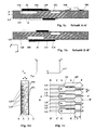
- a section of the ESIJIL printhead according to the invention is represented by a line AA 'in FIG. 1a.
- the middle part 3 is a middle plate structured between two membrane plates 2 and 4.
- PZT elements 31 are attached to the membrane plates.
- Conductor tracks 180 and further mechanical and / or electrical components or integrated circuits 160 are fastened on the membrane plate 2.
- a first group of chambers 101 spaced apart from one another in the z direction is arranged in a first plane of the central part 3.
- a second group of chambers 105 spaced apart from one another in the z direction is arranged.
- this third level of the middle part 3 there is a single row of nozzles 1 for all the nozzles.
- the openings, channels, a suction space 151 and the chambers in the first level are connected via a second level of the central part to chambers or nozzle channels of a third level of the central part.
- the one-piece middle part is formed with ink channels running vertically through and in a number of planes in such a way that an approximately equal ink path length exists.
- the chamber groups are offset from one another in the x, y and z directions to such an extent that all ink paths from the suction chamber to the chambers or from the chambers to the nozzles in the row of nozzles are of equal length at least within one module.
- the ink passes through feeds and openings already shown in DE 42 25 799 A1 into a suction space 151, which is connected via inlet channels 110 to the ink chambers 101 of the first level.
- the ink chambers are connected via ink passage channels 112 through the second level and channels 111 to the nozzles in the nozzle group 1.1, which are arranged in the third level.
- Each ink chamber is assigned a membrane and a PZT element, which deforms the membrane when subjected to an electrical pulse and thus changes the volume of the chamber.
- the chamber volume expands, ink is supplied from the suction space 151.
- the ink drops are ejected in the x direction through a nozzle belonging to the nozzle group 1.1.
- the ink passes through inlet channels 113 having restrictors in the third level to the ink chambers 105 of a further group of chambers and from there via nozzle channels 115 to the nozzles of nozzle group 1.5.
- FIG. 1d shows a section of an edge of the entire ESIJIL print head according to the first variant with a corresponding nozzle arrangement of a row of nozzles 1 in superimposition of the cuts C-C ', D-D', E-E 'and G-G'.
- the PZT elements are not shown for the sake of simplicity.
- nozzles of the nozzle groups alternate with nozzles of the other nozzle groups.
- nozzles of the nozzle group 1.1 and 1.5 belong to an associated chamber 101 and 105 of the first and further chamber groups.
- the chambers 101, 105 belonging to different groups are arranged vertically offset in the y and also horizontally in the x and z directions.
- FIG. 1c shows the position of the chambers in the first level 2 of the ESIJIL printhead in a top view from the component side according to the arrangement according to the first variant.
- the underlying chambers in the third level 4 are drawn with dashed lines in order to position them relative to the first chamber plate clarify.
- Both chamber groups for chambers 101, 105 have an offset of size X in the x direction and an offset of size Z in the z direction.
- the row of nozzles 1 comprises the nozzles belonging to different nozzle groups 1.1, 1.5, which alternate in an advantageous manner in such a way that chamber groups on one level overlap with those on the other level only at the chamber edges.
- the area of overlap F of a chamber of the chamber group 105 with a chamber of the chamber group 101 is hatched.
- the covering area F can be minimized by the offset in the x and z directions.
- photosensitive glass is used as the material for all plates of the print head.
- the structuring, including the formation of the nozzles, is achieved by a photolithographic process and etching of the exposed parts.
- Metal plates can also be used as the material.
- the membrane plate thicknesses must be selected according to the modulus of elasticity. It is manufactured by: Exposure of photoresist surface, etching, thermal bonding or gluing in a manner known per se.
- the manufacturing process for the E / FSIJIL printhead according to the invention will be explained in more detail using the example of the material glass.
- a mask is placed on a wafer made of photosensitive glass. After exposure to UV light, a phase transformation of amorphous materials into its crystalline phase is brought about in the exposed areas by heat treatment. Crystalline material is then removed in layers by etching, as was already proposed by IBM in US Pat. No. 4,092,166.
- the exposures preferably UV light
- the exposures are controlled in terms of intensity and duration in the photolithographic process.
- the depth of the material change is stopped when the corresponding level is reached.
- the exposures are carried out by means of two masks which carry the upper and lower structures. If through-exposure is unavoidable, masking can be carried out before the etching process to ensure that only one side is etched at a time.
- the etching depth is determined by the concentration and duration of the etching bath. An ultrasonic immersion bath is advantageously used.
- the different etching depths can be generated by multi-stage etching, the flatter structures being protected from further etching by masking. In this way, the vertical ones are also Channels can be produced as a connection between the ink chambers on the underside and the nozzles structured on the top.
- the ink chambers on the bottom overlap with those on the top to ensure a high density of the nozzle arrangement.
- D 2a + b + 2s * D
- D 2a + b
- the selectivity s as the ratio of the etching rates between the unexposed part of the sensitive material and the exposed one is between 2% and 5%, for example in the case of photosensitive glass.
- the starting material thickness D of the middle plate is therefore to be chosen according to equation (3) so that it is twice the depth a of an ink chamber plus a min.
- Wall thickness b between the bottoms of the two-sided ink chambers divided by the difference of one with twice the selectivity s of the etching process corresponds to:
- the two membrane plates (top and bottom plate) can preferably have identical dimensions. Their thicknesses should be chosen so that, based on the modulus of elasticity, the width and length of the ink chambers and the bending force of the PZT, there is a sufficient change in the chamber volume which leads to the ejection of an ink drop. Material thicknesses of 0.05 mm to 0.2 mm are preferably used.
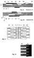
- FIGS. 2a to 2c show a variant according to which a face shooter ink jet in-line print head (FSIJIL print head) according to the invention can be designed, as an alternative to the FSIJIL print head, which is described in pending patent application P 43 36 416.0 has been described.
- FSIJIL print head face shooter ink jet in-line print head
- FIG. 2a shows the section through line A-A 'and in FIG. 2b the section through line B-B' of the FSIJIL printhead according to a first variant.
- Figures 2a and 2b illustrate the ink routing in the FSIJIL printhead.
- the chambers for the row of nozzles on the one hand and for a suction chamber on the other hand are arranged in such a way that ink channels of different lengths, in particular nozzle channels and inlet channels and through-channels, are provided in each plane, the sum of all ink channel lengths in the x, y and z directions, each Chamber is assigned remains approximately constant.
- the other part of the face shooter ink jet print head according to the invention contains further groups with chambers 102 and 106 and a second suction space 152 on the other side of the row of nozzles.
- Figure 2c illustrates in one Top view (component side) shows the position of the chambers 101, 102, 105 and 106 belonging to different groups offset from one another in the vicinity of the row of nozzles.
- twice the nozzle density is achieved.
- the membrane plate 4 must now be designed as a nozzle plate, however. This happens in an advantageous manner only through a subsequent laser beam processing. Any other manufacture before thermal bonding requires precise adjustment.
- the nozzles 1 and through openings 112, 114 can be produced in various ways. They can be etched, burned out with a laser beam or punched with special tools. The selection of the process depends, among other things, on the material used.
- etchants with different concentrations and / or different exposure times are used for the three areas in order to be able to remove the corresponding areas with different depth accuracy, the depth accuracy when etching the areas for through bores being lower than when etching very shallow Areas for the channels in the chamber planes and first the through holes, then the chambers and then the nozzle channels are etched.
- the reverse can also be used.
- the homogeneous and tight-fitting connection of the three plates 2, 3 and 4 is produced by thermal diffusion bonding. Conductor tracks are glued or sputtered on.
- FIG. 2d shows a view of a PZT plate 31 which is fastened on the membrane plate, the positioning effort compared to individual elements being able to be reduced.
- the individual PZT elements are worked out finger-like and provided with electrodes 30.
- PZT elements can be applied by metallizing a first and second pretreated PZT plate and applying it to the first and second membrane plate. If the PZT elements are not yet sufficiently worked out from the plate, a number of individual PZT elements are then separated for that side of the module.
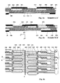
- FIGS. 3a to 3c A second variant for an ESIJIL printhead with an increased resolution can be seen from FIGS. 3a to 3c.
- Figure 3a is a section through the line A-A '
- Figure 3b is a section through the line B-B'
- in Figure 3c is a plan view of the middle plate (component side) of the ESIJIL printhead according to variant two shown.
- the arrangement of the chambers 103 of an additional chamber group between the chambers 101 of the first chamber group and the nozzle line D-D ' can be seen from the top view of the middle plate (component side) in FIG. 3c. From section B-B 'in FIG. 3b it is clear that there is again an ink path of the same length as in the ink paths with respect to the chambers 101 or 105 belonging to the other chamber groups.
- This additional chamber group is preferably fed from the same suction chamber 151.
- FIG. 4a shows a section through the line A-A 'of such an FSIJIL print head according to variant two.
- the chamber 101 of a first chamber group is arranged, which via an ink passage channel 112 and nozzle channel 111 in the third plane of the central part with the nozzle group 1.1 shown. associated nozzle is connected.
- the chamber 106 of a further chamber group is arranged near the nozzle side and the chamber 104 of an additional chamber group near the assembly side.
- the chamber 104 is connected via a - dashed line - ink passage channel 112 and nozzle channels in the third level of the central part to a nozzle (not shown) belonging to nozzle group 1.4, which is adjacent to that nozzle belonging to nozzle group 1.1.
- the section through the line B-B 'of the FSIJIL print head according to variant two shows only the nozzle belonging to the nozzle group 1.5, which is fed from the chamber 105. Adjacent to this nozzle are nozzles belonging to nozzle groups 1.2 and 1.6. The corresponding ink paths from the chambers 102 and 106 of the chamber groups lying to the left of the nozzle line to the associated nozzles are shown in dashed lines.
- the chamber 103 belonging to the additional chamber group lies here to the right of the nozzle line and is connected via channels to the nozzle (not shown) belonging to the nozzle group 1.3.
- FIG. 4c The position of the additional chambers 103 to the right and 104 to the left of the nozzle line can be seen from FIG. 4c, in which the FSIJIL print head according to variant two is shown in a top view of the middle plate (component side).
- These chambers are each again arranged in groups, which are also offset from one another in the z direction. Just as the nozzle groups 1.1 to 1.6 alternate with one another within the nozzle row 1, all the chamber groups have an offset in the z direction.
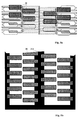
- This adjustment effort can be considerably reduced if a prefabricated PZT plate 311, as shown in FIG. 5b, is used.
- the multiple Comb structure of the PZT plate allows one-time positioning on the membrane plate over the corresponding chambers with little effort.
- the PZT plate is patterned by etching using a conventional photolithographic method.
- the electrode coating 30 of the PZT plate 311 is applied by sputtering and electrolytically reinforced.
- the embodiment for ESIJIL printheads according to FIG. 3 or for FSIJIL printheads according to FIG. 4 can be modified by omitting the chamber group 101 or the chamber groups 101 and 102. It is provided that a group of nozzle channels and a chamber group 105, 106 are arranged on one surface of the central part and a further chamber group 103, 104 spaced apart from the row of nozzles in the x and y directions between the row of nozzles 1 and a row on the other surface is arranged which form the through channels 112 connecting the chambers with the nozzle channels.
- the effect of a larger offset of ink chamber groups against one another on the printed image can be compensated for by constructive (ink channel cross section) and / or electronic measures without the ink path length having to be exactly the same length.
- the different structures on the two opposite surfaces of the middle part 3 allow the nozzle row 1 to be relatively close to one of the two structures.
- the ink path from the chambers to the nozzles or from the suction spaces 151, 152 to the chambers is then different for the mutually offset structures.
- the invention is not limited to the present embodiment. Rather, a number of variants are conceivable which make use of the solution shown, even in the case of fundamentally different types.
Applications Claiming Priority (2)
| Application Number | Priority Date | Filing Date | Title |
|---|---|---|---|
| DE9404328U | 1994-03-10 | ||
| DE9404328U DE9404328U1 (de) | 1994-03-10 | 1994-03-10 | Tintenstrahldruckkopf |
Publications (3)
| Publication Number | Publication Date |
|---|---|
| EP0671270A2 true EP0671270A2 (fr) | 1995-09-13 |
| EP0671270A3 EP0671270A3 (fr) | 1995-12-27 |
| EP0671270B1 EP0671270B1 (fr) | 1998-08-12 |
Family
ID=6905964
Family Applications (1)
| Application Number | Title | Priority Date | Filing Date |
|---|---|---|---|
| EP95250037A Expired - Lifetime EP0671270B1 (fr) | 1994-03-10 | 1995-02-13 | Tête d'impression par jet d'encre |
Country Status (3)
| Country | Link |
|---|---|
| US (1) | US5828390A (fr) |
| EP (1) | EP0671270B1 (fr) |
| DE (2) | DE9404328U1 (fr) |
Families Citing this family (11)
| Publication number | Priority date | Publication date | Assignee | Title |
|---|---|---|---|---|
| DE59509149D1 (de) * | 1994-08-03 | 2001-05-10 | Francotyp Postalia Gmbh | Anordnung für plattenförmige Piezoaktoren und Verfahren zu deren Herstellung |
| DE4443254C1 (de) | 1994-11-25 | 1995-12-21 | Francotyp Postalia Gmbh | Anordnung für einen Tintendruckkopf aus einzelnen Tintendruckmodulen |
| WO1998022288A1 (fr) * | 1996-11-18 | 1998-05-28 | Seiko Epson Corporation | Tete d'ecriture a jet d'encre |
| DE60000584T2 (de) | 1999-01-29 | 2003-08-14 | Seiko Epson Corp | Tintenstrahldruckkopf mit verbesserten Tintenzufuhrkanälen |
| US6328417B1 (en) | 2000-05-23 | 2001-12-11 | Silverbrook Research Pty Ltd | Ink jet printhead nozzle array |
| WO2001089844A1 (fr) * | 2000-05-24 | 2001-11-29 | Silverbrook Research Pty. Ltd. | Systeme de buses d'une tete d'impression a jet d'encre |
| SG152034A1 (en) * | 2000-05-24 | 2009-05-29 | Silverbrook Res Pty Ltd | An ink jet printhead incorporating an array of nozzle assemblies |
| AU2005203479B2 (en) * | 2000-05-24 | 2006-11-23 | Memjet Technology Limited | Inkjet printhead with paired nozzle rows |
| NL1016735C2 (nl) * | 2000-11-29 | 2002-05-31 | Ocu Technologies B V | Werkwijze voor het vormen van een nozzle in een orgaan voor een inkjet printkop, een nozzle-orgaan, een inkjet printkop voorzien van dit nozzle-orgaan en een inkjet printer voorzien van een dergelijke printkop. |
| US20070236537A1 (en) * | 2006-03-29 | 2007-10-11 | Picosys Inc. | Fluid jet print module |
| JP6277731B2 (ja) * | 2014-01-17 | 2018-02-14 | セイコーエプソン株式会社 | 液体噴射ヘッドおよび液体噴射装置 |
Citations (2)
| Publication number | Priority date | Publication date | Assignee | Title |
|---|---|---|---|---|
| DE3311956A1 (de) * | 1982-03-31 | 1983-10-13 | Ricoh Co., Ltd., Tokyo | Farbstrahl-druckerkopf |
| EP0581395A2 (fr) * | 1992-07-31 | 1994-02-02 | Francotyp-Postalia GmbH | Tête d'impression à jet d'encre et son procédé de fabrication |
Family Cites Families (7)
| Publication number | Priority date | Publication date | Assignee | Title |
|---|---|---|---|---|
| DE2349555C2 (de) * | 1973-04-25 | 1983-04-07 | Siemens AG, 1000 Berlin und 8000 München | Druckkopf für Farbflüssigkeits-Spritzdrucker und dergleichen |
| DE2649970A1 (de) * | 1976-10-30 | 1978-05-03 | Olympia Werke Ag | Duesendrucker fuer ein tintenschreibwerk |
| JPS5586767A (en) * | 1978-12-23 | 1980-06-30 | Seiko Epson Corp | Print head |
| JPS58187365A (ja) * | 1982-04-27 | 1983-11-01 | Seiko Epson Corp | オンデマンド型インクジエツト記録ヘツド |
| DE3608205A1 (de) * | 1986-03-12 | 1987-09-17 | Olympia Ag | Piezoelektrisch betriebener schreibkopf fuer tintenmosaikschreibeinrichtungen |
| DE3609154A1 (de) * | 1986-03-19 | 1987-09-24 | Olympia Ag | Piezoelektrisch betriebener schreibkopf fuer tintenmosaikschreibeinrichtungen |
| DE3814720A1 (de) * | 1988-04-30 | 1989-11-09 | Olympia Aeg | Verfahren zur herstellung einer grundplatte mit durch aetzen hergestellte einarbeitungen fuer einen tintendruckkopf |
-
1994
- 1994-03-10 DE DE9404328U patent/DE9404328U1/de not_active Expired - Lifetime
-
1995
- 1995-02-13 EP EP95250037A patent/EP0671270B1/fr not_active Expired - Lifetime
- 1995-02-13 DE DE59503105T patent/DE59503105D1/de not_active Expired - Fee Related
- 1995-02-21 US US08/393,933 patent/US5828390A/en not_active Expired - Lifetime
Patent Citations (2)
| Publication number | Priority date | Publication date | Assignee | Title |
|---|---|---|---|---|
| DE3311956A1 (de) * | 1982-03-31 | 1983-10-13 | Ricoh Co., Ltd., Tokyo | Farbstrahl-druckerkopf |
| EP0581395A2 (fr) * | 1992-07-31 | 1994-02-02 | Francotyp-Postalia GmbH | Tête d'impression à jet d'encre et son procédé de fabrication |
Also Published As
| Publication number | Publication date |
|---|---|
| EP0671270A3 (fr) | 1995-12-27 |
| DE9404328U1 (de) | 1994-05-19 |
| US5828390A (en) | 1998-10-27 |
| EP0671270B1 (fr) | 1998-08-12 |
| DE59503105D1 (de) | 1998-09-17 |
Similar Documents
| Publication | Publication Date | Title |
|---|---|---|
| EP0648607B1 (fr) | Module de tête à jet d'encre pour tête à jet d'encre éjectant de face et procédé pour sa fabrication | |
| EP0581395B1 (fr) | Tête d'impression à jet d'encre | |
| DE69908807T2 (de) | Tröpfchenaufzeichnungsgerät | |
| DE69935179T2 (de) | Strukturierungstechnik unter Verwendung eines Templates und Tintenstrahlsystems | |
| DE3717294C2 (de) | Tintenstrahlaufzeichnungskopf | |
| DE69636021T2 (de) | Tintenstrahldruckkopf und Verfahren zu seiner Herstellung | |
| EP0713777B1 (fr) | Agencement de modules individuels d'impression à encre pour une tête d'impression à encre | |
| EP0615844B1 (fr) | Tête d'impression par jet d'encre modulaire | |
| DE60313230T2 (de) | Tintenstrahldruckkopf | |
| DE3427850C2 (fr) | ||
| DE69934469T2 (de) | Druckköpfe | |
| DE60313233T2 (de) | Tintenstrahlkopf, Verfahren für dessen Herstellung, und Tintenstrahldrucker | |
| DE69824019T2 (de) | Tröpfchen-niederschlagvorrichtung | |
| DE69833154T2 (de) | Mikrovorrichtung | |
| DE60316486T2 (de) | Verfahren zur Herstellung eines Tintenstrahldruckkopfs | |
| EP0671270B1 (fr) | Tête d'impression par jet d'encre | |
| DE60207621T2 (de) | Tintenstrahlaufzeichnungskopf und Tintenstrahlaufzeichnungsapparat | |
| DE3414792A1 (de) | Verfahren zur herstellung eines fluessigkeitsstrahl-schreibkopfes | |
| EP0340448A2 (fr) | Procédé pour la fabrication d'une plaque de fond avec incrustation obtenue par gravure pour tête pour imprimante par jet d'encre | |
| DE4435914C2 (de) | Piezoelektrischer Antrieb für einen Tintenstrahlaufzeichnungskopf und Verfahren zu dessen Herstellung | |
| DE19813470B4 (de) | Tintenstrahldruckkopf | |
| DE69822928T2 (de) | Tintenstrahldruckkopf | |
| EP0713775A2 (fr) | Agencement pour une tête d'impression à jet d'encre modulaire | |
| EP0179452B1 (fr) | Procédé de fabrication de têtes d'impression pour mécanisme d'impression à encre | |
| DE3917434C2 (fr) |
Legal Events
| Date | Code | Title | Description |
|---|---|---|---|
| PUAI | Public reference made under article 153(3) epc to a published international application that has entered the european phase |
Free format text: ORIGINAL CODE: 0009012 |
|
| AK | Designated contracting states |
Kind code of ref document: A2 Designated state(s): CH DE FR GB IT LI |
|
| PUAL | Search report despatched |
Free format text: ORIGINAL CODE: 0009013 |
|
| AK | Designated contracting states |
Kind code of ref document: A3 Designated state(s): CH DE FR GB IT LI |
|
| 17P | Request for examination filed |
Effective date: 19960229 |
|
| RAP1 | Party data changed (applicant data changed or rights of an application transferred) |
Owner name: FRANCOTYP-POSTALIA AKTIENGESELLSCHAFT & CO. |
|
| RAP3 | Party data changed (applicant data changed or rights of an application transferred) |
Owner name: FRANCOTYP-POSTALIA AKTIENGESELLSCHAFT & CO. |
|
| 17Q | First examination report despatched |
Effective date: 19970401 |
|
| GRAG | Despatch of communication of intention to grant |
Free format text: ORIGINAL CODE: EPIDOS AGRA |
|
| GRAG | Despatch of communication of intention to grant |
Free format text: ORIGINAL CODE: EPIDOS AGRA |
|
| GRAH | Despatch of communication of intention to grant a patent |
Free format text: ORIGINAL CODE: EPIDOS IGRA |
|
| GRAH | Despatch of communication of intention to grant a patent |
Free format text: ORIGINAL CODE: EPIDOS IGRA |
|
| GRAA | (expected) grant |
Free format text: ORIGINAL CODE: 0009210 |
|
| AK | Designated contracting states |
Kind code of ref document: B1 Designated state(s): CH DE FR GB IT LI |
|
| REG | Reference to a national code |
Ref country code: CH Ref legal event code: NV Representative=s name: ROTTMANN, ZIMMERMANN + PARTNER AG Ref country code: CH Ref legal event code: EP |
|
| REF | Corresponds to: |
Ref document number: 59503105 Country of ref document: DE Date of ref document: 19980917 |
|
| GBT | Gb: translation of ep patent filed (gb section 77(6)(a)/1977) |
Effective date: 19981014 |
|
| ET | Fr: translation filed | ||
| PLBE | No opposition filed within time limit |
Free format text: ORIGINAL CODE: 0009261 |
|
| STAA | Information on the status of an ep patent application or granted ep patent |
Free format text: STATUS: NO OPPOSITION FILED WITHIN TIME LIMIT |
|
| 26N | No opposition filed | ||
| REG | Reference to a national code |
Ref country code: GB Ref legal event code: IF02 |
|
| REG | Reference to a national code |
Ref country code: CH Ref legal event code: PUE Owner name: DIGITAL GRAPHICS INCORPORATION Free format text: FRANCOTYP-POSTALIA AKTIENGESELLSCHAFT & CO.#TRIFTWEG 21-26#16547 BIRKENWERDER (DE) -TRANSFER TO- DIGITAL GRAPHICS INCORPORATION#517, DEOKE-DON YANGJU-SHI#KYUNGGI-DO, 482-050 (KR) |
|
| REG | Reference to a national code |
Ref country code: FR Ref legal event code: TP |
|
| PGFP | Annual fee paid to national office [announced via postgrant information from national office to epo] |
Ref country code: FR Payment date: 20050228 Year of fee payment: 11 |
|
| PGFP | Annual fee paid to national office [announced via postgrant information from national office to epo] |
Ref country code: CH Payment date: 20050301 Year of fee payment: 11 |
|
| REG | Reference to a national code |
Ref country code: GB Ref legal event code: 732E |
|
| PG25 | Lapsed in a contracting state [announced via postgrant information from national office to epo] |
Ref country code: LI Free format text: LAPSE BECAUSE OF NON-PAYMENT OF DUE FEES Effective date: 20060228 Ref country code: CH Free format text: LAPSE BECAUSE OF NON-PAYMENT OF DUE FEES Effective date: 20060228 |
|
| PGFP | Annual fee paid to national office [announced via postgrant information from national office to epo] |
Ref country code: IT Payment date: 20060228 Year of fee payment: 12 |
|
| REG | Reference to a national code |
Ref country code: CH Ref legal event code: PL |
|
| REG | Reference to a national code |
Ref country code: FR Ref legal event code: ST Effective date: 20061031 |
|
| PG25 | Lapsed in a contracting state [announced via postgrant information from national office to epo] |
Ref country code: FR Free format text: LAPSE BECAUSE OF NON-PAYMENT OF DUE FEES Effective date: 20060228 |
|
| PGFP | Annual fee paid to national office [announced via postgrant information from national office to epo] |
Ref country code: GB Payment date: 20080318 Year of fee payment: 14 Ref country code: DE Payment date: 20080228 Year of fee payment: 14 |
|
| PG25 | Lapsed in a contracting state [announced via postgrant information from national office to epo] |
Ref country code: IT Free format text: LAPSE BECAUSE OF NON-PAYMENT OF DUE FEES Effective date: 20070213 |
|
| GBPC | Gb: european patent ceased through non-payment of renewal fee |
Effective date: 20090213 |
|
| PG25 | Lapsed in a contracting state [announced via postgrant information from national office to epo] |
Ref country code: DE Free format text: LAPSE BECAUSE OF NON-PAYMENT OF DUE FEES Effective date: 20090901 |
|
| PG25 | Lapsed in a contracting state [announced via postgrant information from national office to epo] |
Ref country code: GB Free format text: LAPSE BECAUSE OF NON-PAYMENT OF DUE FEES Effective date: 20090213 |