EP0666478B1 - Vorrichtung zur Impulserzeugung an Fahrzeugrädern - Google Patents
Vorrichtung zur Impulserzeugung an Fahrzeugrädern Download PDFInfo
- Publication number
- EP0666478B1 EP0666478B1 EP95100328A EP95100328A EP0666478B1 EP 0666478 B1 EP0666478 B1 EP 0666478B1 EP 95100328 A EP95100328 A EP 95100328A EP 95100328 A EP95100328 A EP 95100328A EP 0666478 B1 EP0666478 B1 EP 0666478B1
- Authority
- EP
- European Patent Office
- Prior art keywords
- pole ring
- projections
- brake
- wheel
- webs
- Prior art date
- Legal status (The legal status is an assumption and is not a legal conclusion. Google has not performed a legal analysis and makes no representation as to the accuracy of the status listed.)
- Expired - Lifetime
Links
- 238000001514 detection method Methods 0.000 claims description 2
- 210000002105 tongue Anatomy 0.000 claims 1
- 230000015572 biosynthetic process Effects 0.000 description 4
- 238000001816 cooling Methods 0.000 description 2
- 238000010438 heat treatment Methods 0.000 description 2
- 238000004519 manufacturing process Methods 0.000 description 2
- 238000005266 casting Methods 0.000 description 1
- 238000006073 displacement reaction Methods 0.000 description 1
- 238000003754 machining Methods 0.000 description 1
- 239000002184 metal Substances 0.000 description 1
- 238000004080 punching Methods 0.000 description 1
- 238000009423 ventilation Methods 0.000 description 1
Images




Classifications
-
- G—PHYSICS
- G01—MEASURING; TESTING
- G01P—MEASURING LINEAR OR ANGULAR SPEED, ACCELERATION, DECELERATION, OR SHOCK; INDICATING PRESENCE, ABSENCE, OR DIRECTION, OF MOVEMENT
- G01P1/00—Details of instruments
-
- F—MECHANICAL ENGINEERING; LIGHTING; HEATING; WEAPONS; BLASTING
- F16—ENGINEERING ELEMENTS AND UNITS; GENERAL MEASURES FOR PRODUCING AND MAINTAINING EFFECTIVE FUNCTIONING OF MACHINES OR INSTALLATIONS; THERMAL INSULATION IN GENERAL
- F16D—COUPLINGS FOR TRANSMITTING ROTATION; CLUTCHES; BRAKES
- F16D65/00—Parts or details
- F16D65/02—Braking members; Mounting thereof
- F16D65/12—Discs; Drums for disc brakes
-
- G—PHYSICS
- G01—MEASURING; TESTING
- G01P—MEASURING LINEAR OR ANGULAR SPEED, ACCELERATION, DECELERATION, OR SHOCK; INDICATING PRESENCE, ABSENCE, OR DIRECTION, OF MOVEMENT
- G01P3/00—Measuring linear or angular speed; Measuring differences of linear or angular speeds
- G01P3/42—Devices characterised by the use of electric or magnetic means
- G01P3/44—Devices characterised by the use of electric or magnetic means for measuring angular speed
- G01P3/48—Devices characterised by the use of electric or magnetic means for measuring angular speed by measuring frequency of generated current or voltage
- G01P3/481—Devices characterised by the use of electric or magnetic means for measuring angular speed by measuring frequency of generated current or voltage of pulse signals
- G01P3/488—Devices characterised by the use of electric or magnetic means for measuring angular speed by measuring frequency of generated current or voltage of pulse signals delivered by variable reluctance detectors
-
- F—MECHANICAL ENGINEERING; LIGHTING; HEATING; WEAPONS; BLASTING
- F16—ENGINEERING ELEMENTS AND UNITS; GENERAL MEASURES FOR PRODUCING AND MAINTAINING EFFECTIVE FUNCTIONING OF MACHINES OR INSTALLATIONS; THERMAL INSULATION IN GENERAL
- F16D—COUPLINGS FOR TRANSMITTING ROTATION; CLUTCHES; BRAKES
- F16D65/00—Parts or details
- F16D65/02—Braking members; Mounting thereof
- F16D2065/13—Parts or details of discs or drums
- F16D2065/1304—Structure
- F16D2065/1308—Structure one-part
-
- F—MECHANICAL ENGINEERING; LIGHTING; HEATING; WEAPONS; BLASTING
- F16—ENGINEERING ELEMENTS AND UNITS; GENERAL MEASURES FOR PRODUCING AND MAINTAINING EFFECTIVE FUNCTIONING OF MACHINES OR INSTALLATIONS; THERMAL INSULATION IN GENERAL
- F16D—COUPLINGS FOR TRANSMITTING ROTATION; CLUTCHES; BRAKES
- F16D65/00—Parts or details
- F16D65/02—Braking members; Mounting thereof
- F16D2065/13—Parts or details of discs or drums
- F16D2065/1304—Structure
- F16D2065/1328—Structure internal cavities, e.g. cooling channels
-
- F—MECHANICAL ENGINEERING; LIGHTING; HEATING; WEAPONS; BLASTING
- F16—ENGINEERING ELEMENTS AND UNITS; GENERAL MEASURES FOR PRODUCING AND MAINTAINING EFFECTIVE FUNCTIONING OF MACHINES OR INSTALLATIONS; THERMAL INSULATION IN GENERAL
- F16D—COUPLINGS FOR TRANSMITTING ROTATION; CLUTCHES; BRAKES
- F16D65/00—Parts or details
- F16D65/78—Features relating to cooling
Definitions
- the invention relates to a device for generating pulses on vehicle wheels, in particular for speed and / or direction detection, by means of a sensor and a pole ring with a radial plane face for axial contact with a part of the wheel that is rotatably mounted with the wheel Wheel bearings, especially on the wheel hub, brake drum or brake disc, is provided.
- a device for generating pulses on vehicle wheels in particular for speed and / or direction detection, by means of a sensor and a pole ring with a radial plane face for axial contact with a part of the wheel that is rotatably mounted with the wheel Wheel bearings, especially on the wheel hub, brake drum or brake disc, is provided.
- a device is known from US-A-3 764 837.
- Such devices for generating pulses on vehicle wheels by means of a Sensors and a pole ring are known. If the pole ring on the wheel hub is arranged, it is arranged and secured by shrinking. Such shrinking is both spatial and Not possible for thermal reasons in particular if the pole ring is on a brake drum or a brake disc is arranged. In these cases is attached by screwing, taking care must be that by thermal expansion of the brake drum or Brake disc does not cause any undesirable deformation of the pole ring, either lead to damage to the sensor or loosening of the pole ring can. In order to take these requirements into account, it is necessary both the pole ring and the brake disc or brake drum are complex to edit.
- the invention has for its object to develop a device of the type described in such a way that, with simple machining of the rotatably mounted part of the wheel bearing on which the pole ring is to be arranged, there is a structurally simple and quick assembly and disassembly fastening of the pole ring which, on the one hand, does not require any additional fastening parts, such as screws or spring clips, and, on the other hand, avoids harmful influences on the pole ring as a result of thermal expansion of the part of the wheel bearing which supports it.
- the solution to this problem by the invention is characterized in that the rotatably mounted part of the wheel bearing is formed with a plurality of radially extending webs and each with a groove formed in each web, bearing surfaces for the pole ring and that the pole ring with bayonet-like projections radial and axial positioning and position securing within the grooves is provided.
- the radial one and axial positioning and securing of position within the grooves with bayonet-like Protrusions provided pole ring is in a simple way attached to the respective part of the wheel bearing that he with between the Web-like projections are attached to the part and then in this way is rotated in the circumferential direction that the projections into the grooves of the webs intervention. Since the connection between the pole ring and the one receiving the pole ring Part of the wheel bearing exclusively on the in the grooves of the Web-formed contact surfaces takes place, inadmissible heating the pole ring, especially when the brake drum is subjected to high thermal loads or brake disc excluded. The small contact areas between the pole ring and the part of the wheel bearing that supports it ultimately prevent undesirable deformation of the pole ring, even if the brake drum or the brake disc due to a strong Heating expands because of a slight displacement of the components to one another is possible.
- the projections are on one formed approximately radially extending flange of the pole ring and have an in Extent of circumference is smaller than the distance between the webs on.
- the pole ring is positioned in the radial direction according to a further feature of the invention by contacting the lateral surface at least some of the protrusions in the bottom of each groove.
- the positioning of the Pole ring in the axial direction is according to the invention by a resilient Training achieved at least some tabs that work this way lie opposite walls of the grooves formed in the webs.
- At least some protrusions are deformed in an arc.
- the invention proposes at least one projection to be provided with spring tongue-like punched-outs, which in the assembled state with their opposing end faces on opposite Sides of the associated web and in this way secure the position of the pole ring against twisting.
- the wheel bearing shown in Fig. 1 in an overall view leaves a part of an axle body 1 on which a wheel hub 2 is rotatably mounted.
- This wheel hub which is closed by means of a bearing cap 2a, bears in the exemplary embodiment 1 an internally ventilated brake disc 3, which by means of a molded hub flange 3a by fastening screws 3b on the Wheel hub 2 is screwed on.
- the wheel hub 2 is still with wheel bolts 2b provided with which a rim 4 interchangeably attached to the wheel hub 2 becomes.
- a brake frame 5 is attached to the axle body 1 and has a brake caliper 5a includes, in each on opposite sides of the brake disc 3 is provided with a brake pad 6a brake pad 6 is arranged.
- the brake blocks 6 are prevented from falling out of the brake caliper 5a by a retaining spring 7 held.
- the brake pads 6 are actuated by a brake cylinder 8, which is connected to the brake frame 5 via the brake caliper 5a is.
- a sensor 9 is arranged, which cooperates with a pole ring 10, of the brake disk 3 in the exemplary embodiment according to FIG. 1 is arranged.
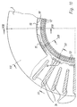
- the formation of the brake disc 3 for receiving the pole ring 10 is shown in FIGS. 2 to 4.
- the formation of an embodiment of the pole ring 10 results from FIGS. 5 to 9.
- Enlarged representations the connection between the pole ring 10 and brake disc 3 show the 10 to 13.
- brake disc 3 has radial within the ventilation channel extending, web-like connecting parts 3c, of which in the embodiment every third to the axis of rotation is extended to a web 20.
- a groove 21 which is shown enlarged in Fig. 4 is.
- the pole ring 10 is inserted, which is based on a Embodiment is shown in FIGS. 5 to 9.
- the stamped from sheet metal and deep-drawn pole ring 10 includes a Cross-section L-shaped ring body 11, which is used to form pole pieces 12 is provided with recesses 13 which by their relative movement to the fixed Sensor 9 generate a pulse to detect the speed and / or the direction of rotation of the wheel is used.
- flange 14 projecting approximately at right angles and extending in the radial direction to the one corresponding to the number of webs 20 in the exemplary embodiment
- Number of projections 15 is provided, which is in the manner of a bayonet interact with the webs 20.
- the pole ring 10 To assemble the pole ring 10, it is attached to the brake disc 3 in such a way that its projections 15 lie between the webs 20. By twisting in the circumferential direction, the projections 15 in the grooves 21 of the Web 20 introduced so that the assembly shown in FIGS. 10 to 13 results.
- the pole ring 10 is positioned radially Direction by contacting the lateral surface of the projections 15 in the base of the Grooves 21, as shown in particular in FIG. 13.
- a resilient training at least some of the protrusions 15 become positioning at the same time the pole ring 10 reached in the axial direction; in the embodiment
- every second projection 15 is deformed in an arc like this 9 shows.
- At least one projection 15 of the pole ring 10 is with spring tongue-like Cutouts 16 provided with their mutually facing end faces rest on opposite sides of the associated web 20 and in this way, the pole ring 10 against accidental rotation from the Secure mounting position. If the pole ring 10 is removed from the brake disc 3 , it is sufficient to push back one of the resilient cutouts 16 and to rotate the pole ring 10 so far that the projections 15 lie between the webs 20 so that the pole ring 10 overall in axial Direction can be removed from the brake disc 3.
- FIGS. 2 to 4 shows that the pole ring 10 shown in FIGS. 2 to 4 not only on a brake disc 3, but also on a brake drum 30 or in a corresponding embodiment also on the wheel hub 2 in the above described way can be arranged.
- FIG. 14 shows a part of a in a manner corresponding to FIG. 1 Axle body 1 and a rotatably mounted wheel hub 2 with a bearing cap 2a.
- the sensor 9 arranged on a carrier 31 can be seen.
- the second embodiment shown with solid lines is the radially inward-pointing flange 14 of the pole ring 10 again provided with projections 15, this time in grooves 21 of webs 20 engage, which are formed on the inner end face of the wheel hub 2 are.
- the result is a corresponding one to the first embodiment Design, only the assignment of flange 14 to Ring body 11 and the location of the grooves 21 from that described above Embodiment differs.
- the first exemplary embodiment results appropriate design for the arrangement of the Pole ring 10 on a brake drum 30.
Landscapes
- Engineering & Computer Science (AREA)
- General Engineering & Computer Science (AREA)
- Physics & Mathematics (AREA)
- General Physics & Mathematics (AREA)
- Mechanical Engineering (AREA)
- Braking Arrangements (AREA)
Description
- Fig. 1
- eine teilweise geschnittene Seitenansicht einer Radlagerung mit einer Scheibenbremse,
- Fig. 2
- eine vergrößerte Darstellung der in der oberen Hälfte geschnittenen und in der unteren Hälfte in einer Seitenansicht dargestellten Bremsscheibe nach Fig. 1,
- Fig. 3
- einen Querschnitt durch die Bremsscheibe gemäß der Schnittlinie III - III in Fig. 2,
- Fig. 4
- eine vergrößerte Detaildarstellung gemäß der Einkreisung IV in Fig. 2,
- Fig. 5
- eine Ansicht des Polringes gemäß Fig. 1 in vergrößerter Darstellung,
- Fig. 6
- einen Querschnitt durch den Polring gemäß der Schnittlinie VI - VI in Fig. 5,
- Fig. 7
- eine vergrößerte Detaildarstellung der Einkreisung VII in Fig. 6,
- Fig. 8
- eine Ansicht eines Teiles des Polringes in Blickrichtung des Pfeiles VIII in Fig. 7,
- Fig. 9
- eine weitere Ansicht eines Teiles des Polringes in Blickrichtung des Pfeiles IX in Fig. 5,
- Fig. 10
- eine vergrößerte Darstellung eines Teiles der mit dem Polring gemäß den Fig. 5 bis 9 versehenen Bremsscheibe gemäß den Fig. 2 bis 4,
- Fig. 11
- einen Querschnitt gemäß der Schnittlinie XI - XI in Fig. 10,
- Fig. 12
- einen Querschnitt gemäß der Schnittlinie XII - XII in Fig. 10 und
- Fig. 13
- einen Querschnitt gemäß der Schnittlinie XIII - XIII in Fig. 10,
- Fig. 14
- zwei weitere Ausführungsbeispiele anhand einer der Fig. 1 entsprechenden Darstellung.
- 1
- Achskörper
- 2
- Radnabe
- 2a
- Lagerkappe
- 2b
- Radbolzen
- 3
- Bremsscheibe
- 3a
- Nabenflansch
- 3b
- Befestigungsschraube
- 3c
- Verbindungsteil
- 4
- Felge
- 5
- Bremsrahmen
- 5a
- Bremssattel
- 6
- Bremsklotz
- 6a
- Bremsbelag
- 7
- Haltefeder
- 8
- Bremszylinder
- 9
- Sensor
- 10
- Polring
- 11
- Ringkörper
- 12
- Polsteg
- 13
- Aussparung
- 14
- Flansch
- 15
- Vorsprung
- 16a
- Ausstanzung
- 20
- Steg
- 21
- Nut
- 30
- Bremstrommel
- 31
- Träger
Claims (6)
- Vorrichtung zur Impulserzeugung an Fahrzeugrädern, insbesondere für die Drehzahl- und/oder Drehrichtungserkennung, mittels eines Sensors und eines Polringes, der mit einer radial verlaufenden Planfläche zur axialen Anlage an einem mit dem Rad drehbar gelagerten Teil der Radlagerung, insbesondere an der Radnabe, Bremstrommel oder Bremsscheibe, versehen ist,
dadurch gekennzeichnet,
daß das drehbar gelagerte Teil (2,3,30) der Radlagerung mit einer Mehrzahl von radial verlaufenden Stegen (20) und mit jeweils einer in jedem Steg (20) ausgebildeten, Anlageflächen für den Polring (10) aufweisenden Nut (21) ausgebildet ist und daß der Polring (10) mit bajonettartigen Vorsprüngen (15) zur radialen und axialen Positionierung und Lagesicherung innerhalb der Nuten (21) versehen ist. - Vorrichtung nach Anspruch 1, dadurch gekennzeichnet, daß die Vorsprünge (15) an einem etwa radial verlaufenden Flansch (14) des Polringes (10) ausgebildet sind und eine in Umfangsrichtung kleinere Erstreckung als der Abstand zwischen den Stegen (20) aufweisen.
- Vorrichtung nach Anspruch 1 oder 2, dadurch gekennzeichnet, daß die Positionierung des Polringes (10) in radialer Richtung durch Anlage der Mantelfläche mindestens einige der Vorsprünge (15) im Grund der jeweiligen Nut (21) erfolgt.
- Vorrichtung nach mindestens einem der Ansprüche 1 bis 3, dadurch gekennzeichnet, daß die Positionierung des Polringes (10) in axialer Richtung durch eine federnde Ausbildung mindestens einiger Vorsprünge (15) erfolgt.
- Vorrichtung nach Anspruch 4, dadurch gekennzeichnet, daß mindestens einige Vorsprünge (15) bogenartig verformt sind.
- Vorrichtung nach mindestens einem der Ansprüche 1 bis 5, dadurch gekennzeichnet, daß mindestens ein Vorsprung (15) mit federzungenartigen Ausstanzungen (16) versehen ist, die in montiertem Zustand mit ihren gegeneinanderweisenden Stirnflächen an gegenüberliegenden Seiten des zugehörigen Steges (20) anliegen.
Applications Claiming Priority (2)
| Application Number | Priority Date | Filing Date | Title |
|---|---|---|---|
| DE4402959A DE4402959C2 (de) | 1994-02-01 | 1994-02-01 | Vorrichtung zur Impulserzeugung an Fahrzeugrädern |
| DE4402959 | 1994-02-01 |
Publications (2)
| Publication Number | Publication Date |
|---|---|
| EP0666478A1 EP0666478A1 (de) | 1995-08-09 |
| EP0666478B1 true EP0666478B1 (de) | 1998-05-06 |
Family
ID=6509162
Family Applications (1)
| Application Number | Title | Priority Date | Filing Date |
|---|---|---|---|
| EP95100328A Expired - Lifetime EP0666478B1 (de) | 1994-02-01 | 1995-01-12 | Vorrichtung zur Impulserzeugung an Fahrzeugrädern |
Country Status (2)
| Country | Link |
|---|---|
| EP (1) | EP0666478B1 (de) |
| DE (2) | DE4402959C2 (de) |
Cited By (5)
| Publication number | Priority date | Publication date | Assignee | Title |
|---|---|---|---|---|
| DE19945137A1 (de) * | 1999-09-21 | 2001-04-12 | Wabco Perrot Bremsen Gmbh | Bremsenkörper |
| DE10145947C1 (de) * | 2001-09-18 | 2002-11-21 | Wabco Perrot Bremsen Gmbh | Bremse |
| DE10237504B4 (de) * | 2002-08-16 | 2006-11-09 | Knorr-Bremse Systeme für Nutzfahrzeuge GmbH | Vorrichtung zur Impulserzeugung an einem Fahrzeugrad und Verfahren zur Montage der Vorrichtung |
| US11131355B2 (en) | 2017-10-24 | 2021-09-28 | Hendrickson Usa, L.L.C. | ABS tone ring mounting structure |
| EP4129784A1 (de) | 2021-08-03 | 2023-02-08 | Brembo North America, Inc. | Antiblockier-sensorring, scheibenbremsband und anordnung |
Families Citing this family (19)
| Publication number | Priority date | Publication date | Assignee | Title |
|---|---|---|---|---|
| US5704692A (en) * | 1995-08-01 | 1998-01-06 | Rockwell Heavy Vehicles Systems, Inc. | Method of welding a sensor bracket to an axle |
| DE19813594B4 (de) * | 1998-03-27 | 2006-06-01 | Volkswagen Ag | Verfahren zur Herstellung eines zweiteilig gefügten Geberrades |
| DE19932585A1 (de) * | 1999-07-13 | 2001-01-18 | Zahnradfabrik Friedrichshafen | Sensor zur Erfassung der Drehzahl eines Rades |
| DE19957632B4 (de) * | 1999-11-30 | 2010-12-30 | Volkswagen Ag | Radbremsenanordnung und Verfahren zur Steuerung des Radbremsmomentes |
| DE10349303B3 (de) | 2003-10-23 | 2005-05-25 | Knorr-Bremse Systeme für Nutzfahrzeuge GmbH | Scheibenbremse |
| JP4728618B2 (ja) * | 2004-09-30 | 2011-07-20 | 本田技研工業株式会社 | パルサリングの取付構造 |
| US7219778B2 (en) | 2004-10-29 | 2007-05-22 | Gunite Corporation | Exciter ring for a brake rotor |
| US7487862B2 (en) | 2005-09-07 | 2009-02-10 | International Truck Intellectual Property Company, Llc | Snap in ABS exciter ring |
| DE102005056063B4 (de) * | 2005-11-24 | 2019-06-06 | Knorr-Bremse Systeme für Nutzfahrzeuge GmbH | An einer Radnabe befestigbare Bremsscheibe |
| DE102006026451B3 (de) * | 2006-06-07 | 2008-03-13 | Knorr-Bremse Systeme für Nutzfahrzeuge GmbH | An einer Radnabe eines Fahrzeuges befestigbare Bremsscheibe |
| JP5422440B2 (ja) * | 2010-02-26 | 2014-02-19 | 本田技研工業株式会社 | 車輪速検出装置 |
| DE102011077034A1 (de) * | 2011-06-07 | 2012-12-13 | Continental Teves Ag & Co. Ohg | Bremsscheibe |
| CN102425627A (zh) * | 2011-12-20 | 2012-04-25 | 郑州精益达汽车零部件有限公司 | 汽车用制动盘 |
| CN105393016A (zh) * | 2013-07-19 | 2016-03-09 | 亨德里克森美国有限责任公司 | 用于重载车辆的盘式制动器转子 |
| US10345325B2 (en) | 2015-03-20 | 2019-07-09 | Honda Motor Co., Ltd. | Wheel speed detecting device, and ring to be detected |
| US10495163B2 (en) | 2017-04-26 | 2019-12-03 | Hendrickson Usa, L.L.C. | Tone ring and attachment structure |
| DE102017112075A1 (de) * | 2017-06-01 | 2018-12-06 | Knorr-Bremse Systeme für Nutzfahrzeuge GmbH | An einem drehbaren Bauteil eines Kraftfahrzeuges verdrehsicher gehaltenes Polrad |
| DE102018203700B4 (de) * | 2018-03-12 | 2023-10-12 | Knorr-Bremse Systeme für Schienenfahrzeuge GmbH | Drehwinkelerfassungseinrichtung für eine Komponente einer Bremse eines Fahrzeugs und Verfahren zum Bestimmen einer Drehwinkelposition der Komponente |
| CN113492809A (zh) * | 2020-04-03 | 2021-10-12 | 株式会社日立制作所 | 轮毂电机的制动装置 |
Family Cites Families (6)
| Publication number | Priority date | Publication date | Assignee | Title |
|---|---|---|---|---|
| DE2034280C3 (de) * | 1970-07-10 | 1973-11-22 | Daimler-Benz Ag, 7000 Stuttgart | Drehzahlgeber, insbesondere fur Bremsschlupfregelanlagen von Kraftfahr zeugen |
| US3890517A (en) * | 1973-11-23 | 1975-06-17 | Kelsey Hayes Co | Wheel speed sensor |
| US3910386A (en) * | 1974-09-23 | 1975-10-07 | Wagner Electric Corp | Quick installation vehicle wheel sensor |
| DE3636039A1 (de) * | 1986-10-23 | 1988-04-28 | Magnetfab Bonn Gmbh | Rotormagnet in ringform |
| DE4212594C2 (de) * | 1992-04-15 | 1995-05-04 | Freudenberg Carl Fa | Radnabendichtung |
| DE4230012C2 (de) * | 1992-09-08 | 1999-08-26 | Knorr Bremse Systeme | ABS-überwachtes Fahrzeugrad |
-
1994
- 1994-02-01 DE DE4402959A patent/DE4402959C2/de not_active Expired - Fee Related
-
1995
- 1995-01-12 DE DE59502071T patent/DE59502071D1/de not_active Expired - Lifetime
- 1995-01-12 EP EP95100328A patent/EP0666478B1/de not_active Expired - Lifetime
Cited By (7)
| Publication number | Priority date | Publication date | Assignee | Title |
|---|---|---|---|---|
| DE19945137A1 (de) * | 1999-09-21 | 2001-04-12 | Wabco Perrot Bremsen Gmbh | Bremsenkörper |
| DE19945137B4 (de) * | 1999-09-21 | 2005-07-21 | Wabco Perrot Bremsen Gmbh | Bremsenkörper |
| DE10145947C1 (de) * | 2001-09-18 | 2002-11-21 | Wabco Perrot Bremsen Gmbh | Bremse |
| EP1293699A2 (de) | 2001-09-18 | 2003-03-19 | WABCO Perrot Bremsen GmbH | Bremsrotor mit Polrad |
| DE10237504B4 (de) * | 2002-08-16 | 2006-11-09 | Knorr-Bremse Systeme für Nutzfahrzeuge GmbH | Vorrichtung zur Impulserzeugung an einem Fahrzeugrad und Verfahren zur Montage der Vorrichtung |
| US11131355B2 (en) | 2017-10-24 | 2021-09-28 | Hendrickson Usa, L.L.C. | ABS tone ring mounting structure |
| EP4129784A1 (de) | 2021-08-03 | 2023-02-08 | Brembo North America, Inc. | Antiblockier-sensorring, scheibenbremsband und anordnung |
Also Published As
| Publication number | Publication date |
|---|---|
| DE4402959C2 (de) | 1997-02-20 |
| EP0666478A1 (de) | 1995-08-09 |
| DE4402959A1 (de) | 1995-08-03 |
| DE59502071D1 (de) | 1998-06-10 |
Similar Documents
| Publication | Publication Date | Title |
|---|---|---|
| DE4402959C2 (de) | Vorrichtung zur Impulserzeugung an Fahrzeugrädern | |
| EP0830520B1 (de) | Bremsscheibe | |
| DE69303076T2 (de) | Lagereinheit für ein Fahrzeugrad | |
| DE3743124A1 (de) | Fahrzeugradanordnung | |
| EP2606252B1 (de) | Bremsenabdeckblech | |
| DE2931400C2 (de) | Nutzfahrzeugrad für Einzel- und Zwillingsanordnung | |
| DE19837446B4 (de) | Scheibenbremssystem | |
| DE3340442C2 (de) | Fahrwerks-Baugruppe für die Anbringung von Radachsen und Bremsen bei Kraftfahrzeugen | |
| DE3744341C2 (de) | ||
| DE69011279T2 (de) | Räder mit eingebauten Bremsscheiben. | |
| DE3340857A1 (de) | Lagerung einer welle in der bohrung eines gehaeuses | |
| DE69203907T2 (de) | Radnabeneinrichtung mit integrierter ABS-Erregerringdichtung. | |
| WO2011050933A1 (de) | Bremsscheibe | |
| DE3149883A1 (de) | Schwimmsattel-teilbelagscheibenbremse | |
| DE2903051A1 (de) | Trommelbremse | |
| DE4131519A1 (de) | Gewichtsverminderter bremsenrotor | |
| DE3916227A1 (de) | Scheibenbremse mit leitbolzenanordnung | |
| DE3616695A1 (de) | Teilbelag-scheibenbremse | |
| DE2320115B2 (de) | Befestigung einer Bremsscheibe einer Achsnabe für Scheibenbremsen in Schienenfahrzeugen | |
| DE3436973A1 (de) | Bremsscheibenanordnung fuer eine innen umgreifende scheibenbremse, insbesondere fuer kraftfahrzeuge | |
| EP0293868B1 (de) | Wellenbremsscheibe für Scheibenbremsen von Schienenfahrzeugen | |
| DE3941928A1 (de) | Scheibenbremsenanordnung | |
| DE4402960C2 (de) | Scheibenbremse | |
| DE4027677C2 (de) | Bremsscheibe für Scheibenbremsen in Kraftfahrzeugen | |
| DE2235244A1 (de) | Halterung fuer eine detektoreinheit bei blockierschutzanlagen von fahrzeugen |
Legal Events
| Date | Code | Title | Description |
|---|---|---|---|
| PUAI | Public reference made under article 153(3) epc to a published international application that has entered the european phase |
Free format text: ORIGINAL CODE: 0009012 |
|
| AK | Designated contracting states |
Kind code of ref document: A1 Designated state(s): DE FR GB IT |
|
| 17P | Request for examination filed |
Effective date: 19950708 |
|
| GRAG | Despatch of communication of intention to grant |
Free format text: ORIGINAL CODE: EPIDOS AGRA |
|
| GRAG | Despatch of communication of intention to grant |
Free format text: ORIGINAL CODE: EPIDOS AGRA |
|
| GRAH | Despatch of communication of intention to grant a patent |
Free format text: ORIGINAL CODE: EPIDOS IGRA |
|
| 17Q | First examination report despatched |
Effective date: 19971024 |
|
| GRAH | Despatch of communication of intention to grant a patent |
Free format text: ORIGINAL CODE: EPIDOS IGRA |
|
| GRAA | (expected) grant |
Free format text: ORIGINAL CODE: 0009210 |
|
| AK | Designated contracting states |
Kind code of ref document: B1 Designated state(s): DE FR GB IT |
|
| GBT | Gb: translation of ep patent filed (gb section 77(6)(a)/1977) |
Effective date: 19980506 |
|
| REF | Corresponds to: |
Ref document number: 59502071 Country of ref document: DE Date of ref document: 19980610 |
|
| ET | Fr: translation filed | ||
| ITF | It: translation for a ep patent filed | ||
| PLBE | No opposition filed within time limit |
Free format text: ORIGINAL CODE: 0009261 |
|
| STAA | Information on the status of an ep patent application or granted ep patent |
Free format text: STATUS: NO OPPOSITION FILED WITHIN TIME LIMIT |
|
| 26N | No opposition filed | ||
| REG | Reference to a national code |
Ref country code: GB Ref legal event code: IF02 |
|
| PGFP | Annual fee paid to national office [announced via postgrant information from national office to epo] |
Ref country code: DE Payment date: 20130129 Year of fee payment: 19 |
|
| PGFP | Annual fee paid to national office [announced via postgrant information from national office to epo] |
Ref country code: IT Payment date: 20140127 Year of fee payment: 20 Ref country code: FR Payment date: 20140124 Year of fee payment: 20 |
|
| PGFP | Annual fee paid to national office [announced via postgrant information from national office to epo] |
Ref country code: GB Payment date: 20140123 Year of fee payment: 20 |
|
| REG | Reference to a national code |
Ref country code: DE Ref legal event code: R119 Ref document number: 59502071 Country of ref document: DE |
|
| REG | Reference to a national code |
Ref country code: DE Ref legal event code: R119 Ref document number: 59502071 Country of ref document: DE Effective date: 20140801 |
|
| PG25 | Lapsed in a contracting state [announced via postgrant information from national office to epo] |
Ref country code: DE Free format text: LAPSE BECAUSE OF NON-PAYMENT OF DUE FEES Effective date: 20140801 |
|
| REG | Reference to a national code |
Ref country code: GB Ref legal event code: PE20 Expiry date: 20150111 |
|
| PG25 | Lapsed in a contracting state [announced via postgrant information from national office to epo] |
Ref country code: GB Free format text: LAPSE BECAUSE OF EXPIRATION OF PROTECTION Effective date: 20150111 |