EP0664922B1 - Spule für ein elektromagnetisches relais - Google Patents
Spule für ein elektromagnetisches relais Download PDFInfo
- Publication number
- EP0664922B1 EP0664922B1 EP93920677A EP93920677A EP0664922B1 EP 0664922 B1 EP0664922 B1 EP 0664922B1 EP 93920677 A EP93920677 A EP 93920677A EP 93920677 A EP93920677 A EP 93920677A EP 0664922 B1 EP0664922 B1 EP 0664922B1
- Authority
- EP
- European Patent Office
- Prior art keywords
- winding
- coil
- channel
- flange
- connection element
- Prior art date
- Legal status (The legal status is an assumption and is not a legal conclusion. Google has not performed a legal analysis and makes no representation as to the accuracy of the status listed.)
- Expired - Lifetime
Links
Images

Classifications
-
- H—ELECTRICITY
- H01—ELECTRIC ELEMENTS
- H01H—ELECTRIC SWITCHES; RELAYS; SELECTORS; EMERGENCY PROTECTIVE DEVICES
- H01H50/00—Details of electromagnetic relays
- H01H50/02—Bases; Casings; Covers
- H01H50/04—Mounting complete relay or separate parts of relay on a base or inside a case
- H01H50/041—Details concerning assembly of relays
- H01H50/042—Different parts are assembled by insertion without extra mounting facilities like screws, in an isolated mounting part, e.g. stack mounting on a coil-support
-
- H—ELECTRICITY
- H01—ELECTRIC ELEMENTS
- H01H—ELECTRIC SWITCHES; RELAYS; SELECTORS; EMERGENCY PROTECTIVE DEVICES
- H01H50/00—Details of electromagnetic relays
- H01H50/44—Magnetic coils or windings
-
- H—ELECTRICITY
- H01—ELECTRIC ELEMENTS
- H01H—ELECTRIC SWITCHES; RELAYS; SELECTORS; EMERGENCY PROTECTIVE DEVICES
- H01H50/00—Details of electromagnetic relays
- H01H50/44—Magnetic coils or windings
- H01H2050/446—Details of the insulating support of the coil, e.g. spool, bobbin, former
-
- H—ELECTRICITY
- H01—ELECTRIC ELEMENTS
- H01H—ELECTRIC SWITCHES; RELAYS; SELECTORS; EMERGENCY PROTECTIVE DEVICES
- H01H50/00—Details of electromagnetic relays
- H01H50/02—Bases; Casings; Covers
- H01H50/021—Bases; Casings; Covers structurally combining a relay and an electronic component, e.g. varistor, RC circuit
-
- H—ELECTRICITY
- H01—ELECTRIC ELEMENTS
- H01H—ELECTRIC SWITCHES; RELAYS; SELECTORS; EMERGENCY PROTECTIVE DEVICES
- H01H50/00—Details of electromagnetic relays
- H01H50/14—Terminal arrangements
-
- H—ELECTRICITY
- H01—ELECTRIC ELEMENTS
- H01H—ELECTRIC SWITCHES; RELAYS; SELECTORS; EMERGENCY PROTECTIVE DEVICES
- H01H50/00—Details of electromagnetic relays
- H01H50/44—Magnetic coils or windings
- H01H50/443—Connections to coils
Definitions
- Such a coil for a relay is described in published patent application WO-A-9111818.
- By fastening the respective connection element in a plug-in channel running parallel to the coil axis it is possible to first connect the coil ends to the winding piece and then to insert the fastening section further into the coil body in order to achieve strain relief for the winding ends.
- the known coil connecting element mentioned above is designed to be relatively complicated.
- the fastening section is bent at right angles to the actual coil connecting element, and the winding piece extends to the side beyond the circumferential contour of the coil flange in order to enable the coil ends to be wound easily. In the area of the face of the flange such a winding would not be possible because further projections of the coil body are provided for receiving contact elements.
- the known coil requires a large volume, in particular a large width, especially because of the winding piece projecting outward beyond the coil flange; in addition, the winding ends are at risk during further assembly.
- a coil is also known from EP-A-0 199 119, which has part of the features mentioned at the beginning.
- the coil connection elements are inserted there as flat parts in plug-in channels of the flange.
- the winding pieces are initially bent outwards over the circumferential contour of the flange in order to enable winding of the winding ends. After winding, they are bent into the area of the flange, which results in strain relief and ensures the narrow design of the coil.
- the object of the invention is to design a coil of the type mentioned in such a way that an effective strain relief of the winding ends is possible without the outer dimensions of the winding pieces exceeding the contour of the coil body or the flanges.
- the winding ends should be protected as far as possible against damage during the assembly.
- this object is achieved with a coil of the type mentioned at the outset in that the coil connecting element extends with the fastening section and the winding part in a common sheet metal plane parallel to the coil axis on the end face in front of the flange, in that the approach containing the plug-in channel extends only over a lower part of the flange Height of the flange extends, wherein the approach, the coil connection element and the winding piece are formed such that when the coil connection element is inserted in the plug-in channel, the winding piece is above the shoulder and within the bobbin width and predetermined by the contour of the flange -Height extends so that the winding piece in the winding position has an axial distance from the flange that enables automatic winding and that an inlet channel is formed parallel to the plug-in channel in the attachment of the flange, which leads the winding end from the winding piece to the winding space.
- the winding piece of the coil connection element is located in the region of the outer circumference of the coil flange and is pushed into the winding space for strain relief
- this winding piece is arranged behind the coil flange and set back against its contour. Due to the additional parallel inlet channel, the winding end of the coil does not have to be guided over the outer circumference of the flange, but rather passes through this flange within the inlet channel parallel to the axial direction of the coil. Since the winding piece is at a relatively large distance from the flange during winding, the winding end can also be wound and fastened within the flange contour.
- connection element By the further pushing the connection element in the direction of the coil flange then enables the strain relief, the winding piece approaching the flange.
- the inlet channel does not run radially on the winding space side of the coil flange, but parallel to the axis from the outside of the flange into the winding space. This also results in the desired strain relief.
- the coil connection element extends with its fastening section and the winding part essentially in a single sheet metal plane parallel to the coil axis.
- the coil connecting element can be produced from a sheet metal strip by simple cutting and without bending processes.
- the fastening section has a plier-shaped cutout, with which it is pressed onto a transverse web of the plug-in channel in the coil former. It is expedient to define a first winding position and a second strain relief position for the coil connecting element by means of a locking tooth on the coil connecting element and / or two locking notches in the plug-in channel.
- the coil shown in the drawing has a coil body 1 made of plastic with a tubular winding support 2 and two flanges 3 and 4.
- the winding support has an axial opening 5 for receiving a coil core, not shown.
- the coil is intended as a basic element for an electromagnetic relay, the further construction of the relay being familiar to the person skilled in the art and need not be shown or described further.
- the flange 3 has a pocket-shaped extension 6 which, for. B. could serve to accommodate contact elements, not shown.
- plug-in channels 7 for plugging in mirror-image-shaped coil connection elements 8, which in the exemplary embodiment shown are designed as flat plugs.
- a fastening section 10 is used to fasten the coil connecting elements, which is attached with a pliers-shaped cutout 11 to a transverse web 12 of the flange 3 (see also FIG. 4).
- the plug-in channel 7 is closed off from the winding space 13 formed between the two flanges 3 and 4 by an insulating wall 14.
- the crossbar 12 has two notches 15 and 16, while the coil connecting element 8 forms a locking tooth 17 in the cutout 11.
- the flange 3 has an inlet channel 18 on both sides for receiving the winding ends to be connected to the winding part.
- the two coil connection elements 8 with the fastening section 10 are first partially inserted into the plug-in channel 7, to the extent that the locking tooth 17 with the first locking notch 15 in Intervention comes. So that the coil connection elements are fixed so far that the winding ends can be attached.
- a coil winding 19 according to FIG. 2 is then applied to the winding carrier, and the winding ends 20 thereof are guided through the inlet channels 18 and wound onto one winding piece 9 each.
- the winding ends 20 are mechanically and electrically connected to the respective winding piece by soldering or welding (see FIG. 3).
- the coil connection elements 8 are then inserted further into the plug-in channel 7 until the respective locking tooth 17 engages in the notch 16 and the coil connection elements 8 reach the dashed position 21 according to FIG. 4. This state is shown in perspective in FIG.
- the coil connection elements additionally have molded-on welding bosses 22, to which, according to FIG. 3, an additional component 23, for example a diode or a resistor, can be welded or soldered.
- an additional component 23 for example a diode or a resistor
- the coil connection elements with the coil body hanging thereon are fastened in a relay base in a known manner, for example by inserting and notching ribs 24, which cannot be described further here.
Landscapes
- Physics & Mathematics (AREA)
- Electromagnetism (AREA)
- Electromagnets (AREA)
- Magnetic Treatment Devices (AREA)
- Burglar Alarm Systems (AREA)
- Breakers (AREA)
- Transformers For Measuring Instruments (AREA)
- Relay Circuits (AREA)
Description
- Die Erfindung betrifft eine Spule mit
- einem Spulenkörper, der zwei Flansche besitzt, welche zwischen einander einen Wickelraum mit einer Erregerwicklung begrenzen;
- mindestens einem Spulenanschlußelement mit einem Befestigungsabschnitt;
- jeweils einem einstückig mit dem Spulenanschlußelement verbundenen Anwickelstück für ein Wicklungsende, wobei mindestens einer der Flansche in einem stirnseitig vorspringenden Ansatz zumindest einen zur Spulenachse parallel verlaufenden Steckkanal für den Befestigungsabschnitt des Spulenanschlußelementes besitzt und wobei der Befestigungsabschnitt mit dem Steckkanal ineinandergreifende Rastelemente aufweist, welche für das Spulenanschlußelement beim Einstecken eine Anwickelposition und, nachdem das Spulenanschlußelement mit dem Befestigungsabschnitt weiter in den Steckkanal eingeschoben ist, eine Zugentlastungsposition festlegen.
- Eine derartige Spule für ein Relais ist in der veröffentlichten Patentanmeldung WO-A-9111818 beschrieben. Durch die Befestigung des jeweiligen Anschlußelementes in einem zur Spulenachse parallel verlaufenden Steckkanal ist es möglich, die Spulenenden zunächst mit dem Anwickelstück zu verbinden und danach den Befestigungsabschnitt weiter in den Spulenkörper einzustecken, um auf diese Weise eine Zugentlastung der Wicklungsenden zu erreichen. Allerdings ist das oben erwähnte bekannte Spulenanschlußelement verhältnismäßig kompliziert gestaltet. Der Befestigungsabschnitt ist rechtwinkelig zu dem eigentlichen Spulenanschlußelement gebogen, und das Anwickelstück erstreckt sich über die Umfangskontur des Spulenflansches hinaus zur Seite, um ein leichtes Anwickeln der Spulenenden zu ermöglichen. Im Bereich der Stirnseite des Flansches wäre ein solches Anwickeln nicht möglich, weil weitere Vorsprünge des Spulenkörpers zur Aufnahme von Kontaktelementen vorgesehen sind. Vor allem durch das nach außen über den Spulenflansch vorstehende Anwickelstück benötigt die bekannte Spule ein großes Volumen, insbesondere eine große Breite; außerdem sind die Wicklungsenden bei der weiteren Montage gefährdet.
- Aus der EP-A-0 199 119 ist ebenfalls eine Spule bekannt, welche einen Teil der eingangs genannten Merkmale aufweist. Die Spulenanschlußelemente sind dort als flache Teile in Steckkanäle des Flansches eingesteckt. Allerdings sind dabei die Anwickelstücke zunächst über die Umfangskontur des Flansches nach außen gebogen, um das Anwickeln der Wicklungsenden zu ermöglichen. Nach dem Wickeln werden sie in den Bereich des Flansches hineingebogen, wodurch sich eine Zugentlastung ergibt und die schmale Bauform der Spule sichergestellt wird.
- Aufgabe der Erfindung ist es, eine Spule der eingangs genannten Art so zu gestalten, daß eine wirksame Zugentlastung der Wicklungsenden möglich ist, ohne daß die Außenabmessungen der Anwickelstücke über die Kontur des Spulenkörpers bzw. der Flansche hinausgehen. Außerdem sollen die Wicklungsenden möglichst gegen Beschädigung im Verlauf der Montage geschützt werden.
- Erfindungsgemäß wird dieses Ziel bei einer Spule der eingangs genannten Art dadurch erreicht, daß das Spulenanschlußelement sich mit dem Befestigungsabschnitt und dem Anwickelstück in einer gemeinsamen Blechebene parallel zur Spulenachse stirnseitig vor dem Flansch erstreckt, daß der den Steckkanal enthaltende Ansatz sich nur über einen unteren Teil der Höhe des Flansches erstreckt, wobei der Ansatz, das Spulenanslußelement und das Anwickelstück derart gebildet sind, daß bei im Steckkanal eingestecktem Spulenanschlußelement das Anwickelstück sich oberhalb des Ansatzes und innerhalb der durch die Kontur des Flansches vorgegebenen Spulenkörper-Breite und -Höhe erstreckt, so daß das Anwickelstück in der Anwickelposition einen das automatische Anwickeln ermöglichenden axialen Abstand von dem Flansch aufweist und daß parallel zum Steckkanal in dem Ansatz des Flansches ein Einlaufkanal ausgebildet ist, der das Wicklungsende vom Anwickelstück bis zum Wickelraum führt.
- Während bei dem Relais gemäß WO-A-9111818 das Anwickelstück des Spulenanschlußelementes sich im Bereich des Außenumfangs des Spulenflansches befindet und zur Zugentlastung in den Wickelraum hineingeschoben wird, ist bei der vorliegenden Erfindung dieses Anwickelstück hinter dem Spulenflansch angeordnet und gegenüber dessen Kontur zurückgesetzt. Durch den zusätzlichen parallelen Einlaufkanal braucht das Wicklungsende der Spule auch nicht über den Außenumfang des Flansches geführt werden, sondern es durchsetzt innerhalb des Einlaufkanals diesen Flansch parallel zur Achsrichtung der Spule. Da beim Wickeln das Anwickelstück einen verhältnismäßig großen Abstand zum Flansch besitzt, kann das Wicklungsende auch innerhalb der Flanschkontur angewickelt und befestigt werden. Durch das weitere Einschieben des Anschlußelementes in Richtung auf den Spulenflansch wird dann die Zugentlastung ermöglicht, wobei sich das Anwickelstück an den Flansch annähert. Der Einlaufkanal verläuft hier im Gegensatz zu bekannten Einlaufkanälen nicht radial auf der Wickelraumseite des Spulenflansches, sondern achsparallel von der Außenseite des Flansches hinein zum Wickelraum. Auf diese Weise ergibt sich auch die angestrebte Zugentlastung.
- Erfindungsgemäß erstreckt sich das Spulenanschlußelement mit seinem Befestigungsabschnitt und dem Anwickelstück im wesentlichen in einer einzigen Blechebene parallel zur Spulenachse. Dadurch ist das Spulenanschlußelement durch einfaches Schneiden und ohne Biegevorgänge aus einem Blechstreifen herstellbar.
- In bevorzugter Ausgestaltung besitzt der Befestigungsabschnitt einen zangenförmigen Ausschnitt, mit welchem er auf einen Quersteg des Steckkanals im Spulenkörper aufgepreßt wird. Dabei ist es zweckmäßig, mittels eines Rastzahns an dem Spulenanschlußelement und/oder zwei Rastkerben im Steckkanal eine erste Anwickelposition und eine zweite Zugentlastungsposition für das Spulenanschlußelement festzulegen.
- Die Erfindung wird nachfolgend an einem Ausführungsbeispiel anhand der Zeichnung näher erläutert. Es zeigen
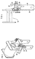
- Figuren 1 bis 3 einen Spulenkörper mit Spulenanschlußelementen in perspektivischer Ansicht in drei aufeinanderfolgenden Montagezuständen,
- Figur 4 eine teilweise geschnittene Seitenansicht eines Spulenkörpers mit einem Spulenanschlußelement.
- Die in der Zeichnung dargestellte Spule besitzt einen Spulenkörper 1 aus Kunststoff mit einem rohrförmigen Wicklungsträger 2 und zwei Flanschen 3 und 4. Der Wicklungsträger besitzt einen axialen Druchbruch 5 zur Aufnahme eines nicht dargestellten Spulenkerns. Die Spule ist als Grundelement für ein elektromagnetisches Relais bestimmt, wobei der weitere Aufbau des Relais dem Fachmann geläufig ist und nicht weiter dargestellt oder beschrieben zu werden braucht.
- Der Flansch 3 besitzt einen taschenförmigen Ansatz 6, der z. B. zur Aufnahme von nicht dargestellten Kontaktelementen dienen könnte. Außerdem ist er mit Steckkanälen 7 zum Einstecken von spiegelbildlich gestalteten Spulenanschlußelementen 8 versehen, die im gezeigten Ausführungsbeispiel als Flachstecker ausgebildet sind. An den beiden Spulenanschlußelementen 8 ist jeweils ein Anwickelstück 9 nach oben in der gleichen Ebene liegend angeformt. Zur Befestigung der Spulenanschlußelemente dient jeweils ein Befestigungsabschnitt 10, der mit einem zangenförmigen Ausschnitt 11 auf einen Quersteg 12 des Flansches 3 aufgesteckt ist (siehe auch Figur 4). Wie in Figur 4 weiter gezeigt ist, ist der Steckkanal 7 zu dem zwischen den beiden Flanschen 3 und 4 gebildeten Wickelraum 13 hin durch eine Isolierwand 14 abgeschlossen.
- Der Quersteg 12 besitzt zwei Rastkerben 15 und 16, während das Spulenanschlußelement 8 in dem Ausschnitt 11 einen Rastzahn 17 bildet. Neben dem jeweiligen Steckkanal 7 und parallel zu diesem besitzt der Flansch 3 beiderseits je einen Einlaufkanal 18 zur Aufnahme der mit dem Anwickelstück zu verbindenden Wicklungsenden.
- Bei der Montage der Spule werden zunächst die beiden Spulenanschlußelemente 8 mit dem Befestigungsabschnitt 10 teilweise in den Steckkanal 7 eingesteckt, und zwar soweit, daß der Rastzahn 17 mit der ersten Rastkerbe 15 in Eingriff kommt. Damit sind die Spulenanschlußelemente soweit fixiert, daß die Wicklungsenden befestigt werden können. Danach wird eine Spulenwicklung 19 gemäß Figur 2 auf den Wicklungsträger aufgebracht, und deren Wicklungsenden 20 werden durch die Einlaufkanäle 18 geführt und an jeweils ein Anwickelstück 9 gewickelt. Durch Verlöten oder Verschweißen (siehe Figur 3) werden die Wicklungsenden 20 mit dem jeweiligen Anwickelstück mechanisch und elektrisch verbunden. Danach werden die Spulenanschlußelemente 8 weiter in den Steckkanal 7 eingesteckt, bis der jeweilige Rastzahn 17 in die Kerbe 16 eingreift und die Spulenanschlußelemente 8 die gestrichelte Position 21 gemäß Figur 4 erreichen. Dieser Zustand ist in Figur 3 perspektivisch gezeigt.
- Die Spulenanschlußelemente besitzen im vorliegenden Beispiel zusätzlich angeformte Schweißbuckel 22, an welche gemäß Figur 3 ein zusätzliches Bauelement 23, beispielsweise eine Diode oder ein Widerstand, angeschweißt oder gelötet werden kann. Die Befestigung der Spulenanschlußelemente mit dem daran hängenden Spulenkörper erfolgt in einem Relaissockel auf bekannte Weise, beispielsweise durch Einstecken und Kerbverformung von Rippen 24, was hier nicht weiter zu beschreiben ist.
Claims (5)
- Spule für ein elektromagnetisches Relais mit:- einem Spulenkörper (1), der zwei Flansche (3, 4) besitzt, welche zwischen einander einen Wickelraum (13) mit einer Erregerwicklung (19) begrenzen;- mindestens einem Spulenanschlußelement (8) mit einem Befestigungsabschnitt (10);- jeweils einem einstückig mit dem Spulenanschlußelement (8) verbundenen Anwickelstück (9) für ein Wicklungsende (20), wobei mindestens einer der Flansche (3) in einem stirnseitig vorspringenden Ansatz (6) zumindest einen zur Spulenachse parallel verlaufenden Steckkanal (7) für den Befestigungsabschnitt (10) des Spulenanschlußelementes (8) besitzt und wobei der Befestigungsabschnitt (10) mit dem Steckkanal (7) ineinandergreifende Rastelemente (15, 16, 17) aufweist, welche für das Spulenanschlußelement (8) beim Einstecken eine Anwickelposition und, nachdem das Spulenanschlußelement (8) mit dem Befestigungsabschnitt (10) weiter in den Steckkanal (7) eingeschoben ist, eine Zugentlastungsposition festlegen,dadurch gekennzeichnet,daß das Spulenanschlußelement (8) sich mit dem Befestigungsabschnitt (10) und dem Anwickelstück (9) in einer gemeinsamen Blechebene parallel zur Spulenachse stirnseitig vor dem Flansch (3) erstreckt,daß der den Steckkanal (7) enthaltende Ansatz (6) sich nur über einen unteren Teil der Höhe des Flansches (3) erstreckt, wobei der Ansatz (6), das Spulenanschlußelement (8) und das Anwickelstück (9) derart gebildet sind, daß bei im Steckkanal (7) eingestecktem Spulenanschlußelement (8) das Anwickelstück (9) sich oberhalb des Ansatzes (6) und innerhalb der durch die Kontur des Flansches (3) vorgegebenen Spulenkörper-Breite und -Höhe erstreckt, so daß das Anwickelstück (9) in der Anwickelposition einen das automatische Anwickeln ermöglichenden axialen Abstand von dem Flansch (3) aufweist unddaß parallel zum Steckkanal (7) in dem Ansatz (6) des Flansches ein Einlaufkanal (18) ausgebildet ist, der das Wicklungsende (20) vom Anwickelstück (9) bis zum Wickelraum (13) führt.
- Spule nach Anspruch 1, dadurch gekennzeichnet, daß der Befestigungsabschnitt (10) mittels eines zangenförmigen Ausschnitts (11) auf einen Quersteg (12) des Steckkanals (7) aufgepreßt ist.
- Spule nach Anspruch 1 oder 2, dadurch gekennzeichnet, daß der Steckkanal (7) zum Wickelraum (13) hin eine Isolierwand (14) besitzt.
- Spule nach einem der Ansprüche 1 bis 3, dadurch gekennzeichnet, daß der Befestigungsabschnitt (10) einen Rastzahn (17) aufweist, mittels dessen er in eine erste Rastkerbe (15) des Ansatzes (6) zur Festlegung der Anwickelposition und in eine zweite Rastkerbe (16) des Ansatzes (6) zur Festlegung der Zugentlastungsposition einrastbar ist.
- Spule nach einem der Ansprüche 1 bis 4, dadurch gekennzeichnet, daß an dem Spulenanschußelement (8) jeweils ein Schweißbuckel (22) zur Befestigung und Kontaktierung eines zusätzlichen Bauelementes (23) vorgesehen ist.
Applications Claiming Priority (3)
| Application Number | Priority Date | Filing Date | Title |
|---|---|---|---|
| DE9213889U | 1992-10-14 | ||
| DE9213889U DE9213889U1 (de) | 1992-10-14 | 1992-10-14 | Spule für ein elektromagnetisches Relais |
| PCT/DE1993/000935 WO1994009505A1 (de) | 1992-10-14 | 1993-10-05 | Spule für ein elektromagnetisches relais |
Publications (2)
| Publication Number | Publication Date |
|---|---|
| EP0664922A1 EP0664922A1 (de) | 1995-08-02 |
| EP0664922B1 true EP0664922B1 (de) | 1996-12-27 |
Family
ID=6884827
Family Applications (1)
| Application Number | Title | Priority Date | Filing Date |
|---|---|---|---|
| EP93920677A Expired - Lifetime EP0664922B1 (de) | 1992-10-14 | 1993-10-05 | Spule für ein elektromagnetisches relais |
Country Status (8)
| Country | Link |
|---|---|
| EP (1) | EP0664922B1 (de) |
| JP (1) | JP3580814B2 (de) |
| AT (1) | ATE146898T1 (de) |
| CZ (1) | CZ281842B6 (de) |
| DE (2) | DE9213889U1 (de) |
| ES (1) | ES2095669T3 (de) |
| SI (1) | SI9300538A (de) |
| WO (1) | WO1994009505A1 (de) |
Families Citing this family (3)
| Publication number | Priority date | Publication date | Assignee | Title |
|---|---|---|---|---|
| DE4427767C2 (de) * | 1994-08-05 | 2001-04-26 | Bosch Gmbh Robert | Spulenkörper mit Umspritzung und Verfahren zu dessen Herstellung |
| EP3547343B1 (de) | 2016-11-24 | 2021-04-21 | Xiamen Hongfa Automotive Electronics Co., Ltd. | Einführstruktur zwischen statischer feder und spule |
| CN112086318A (zh) * | 2020-08-26 | 2020-12-15 | 厦门宏发汽车电子有限公司 | 一种便于自动化装配的继电器 |
Family Cites Families (4)
| Publication number | Priority date | Publication date | Assignee | Title |
|---|---|---|---|---|
| US4684909A (en) * | 1985-03-26 | 1987-08-04 | Siemens Aktiengesellschaft | Electromagnetic relay |
| DE3644113A1 (de) * | 1986-12-23 | 1988-07-07 | Bbc Brown Boveri & Cie | Elektromagnetischer antrieb fuer ein schaltgeraet sowie herstellungsverfahren fuer einen anschlussbereit bestueckten spulenkoerper dieses antriebes |
| WO1991011818A1 (de) * | 1990-01-30 | 1991-08-08 | Siemens Aktiengesellschaft | Elektromagnetisches relais |
| EP0501070B2 (de) * | 1991-02-27 | 2003-05-14 | Takamisawa Electric Co., Ltd. | Elektromagnetisches Kleinrelais |
-
1992
- 1992-10-14 DE DE9213889U patent/DE9213889U1/de not_active Expired - Lifetime
-
1993
- 1993-10-05 ES ES93920677T patent/ES2095669T3/es not_active Expired - Lifetime
- 1993-10-05 CZ CZ95876A patent/CZ281842B6/cs not_active IP Right Cessation
- 1993-10-05 WO PCT/DE1993/000935 patent/WO1994009505A1/de not_active Ceased
- 1993-10-05 EP EP93920677A patent/EP0664922B1/de not_active Expired - Lifetime
- 1993-10-05 DE DE59304922T patent/DE59304922D1/de not_active Expired - Lifetime
- 1993-10-05 AT AT93920677T patent/ATE146898T1/de active
- 1993-10-05 JP JP50950294A patent/JP3580814B2/ja not_active Expired - Lifetime
- 1993-10-14 SI SI9300538A patent/SI9300538A/sl unknown
Also Published As
| Publication number | Publication date |
|---|---|
| DE9213889U1 (de) | 1994-02-10 |
| WO1994009505A1 (de) | 1994-04-28 |
| JP3580814B2 (ja) | 2004-10-27 |
| CZ281842B6 (cs) | 1997-02-12 |
| DE59304922D1 (de) | 1997-02-06 |
| SI9300538A (en) | 1994-06-30 |
| ES2095669T3 (es) | 1997-02-16 |
| JPH08502383A (ja) | 1996-03-12 |
| ATE146898T1 (de) | 1997-01-15 |
| CZ87695A3 (en) | 1995-11-15 |
| EP0664922A1 (de) | 1995-08-02 |
Similar Documents
| Publication | Publication Date | Title |
|---|---|---|
| DE4419055C2 (de) | Chip-Schmelzsicherung | |
| EP0536523B1 (de) | Anschlussklemme | |
| DE69523138T2 (de) | Netzfilter | |
| DE10233251A1 (de) | Joch für eine elektromagnetische Kupplung | |
| EP0199119B1 (de) | Elektromagnetisches Relais | |
| DE19809706B4 (de) | Quetschklemme | |
| EP0793243A1 (de) | Transformator | |
| EP0051103A1 (de) | Vorrichtung zum Anklemmen einer isolierten Kabelader an ein Kontaktelement | |
| DE69123643T2 (de) | Leitungsfiltereinrichtung | |
| EP0655169B2 (de) | Bürstenhalter für elektromotoren | |
| DE69319259T2 (de) | Verbesserte Kontakte für den Anschluss von Spulenwicklungen | |
| EP0528833B1 (de) | Elektromagnetisches schaltsystem und verfahren zu dessen herstellung | |
| EP0513010B1 (de) | Elektromagnetisches relais | |
| DE69015243T2 (de) | Anschlussvorrichtung. | |
| DE9213889U1 (de) | Spule für ein elektromagnetisches Relais | |
| EP0226907A2 (de) | Relais | |
| DE2618317C2 (de) | Adapter zur Verbindung elektromagnetischer Schaltgeräte mit gedruckten Leiterplatten | |
| EP0139980A2 (de) | Kabelschelle | |
| EP0521181B1 (de) | PTC-Heizkörper | |
| DE2936616C2 (de) | Verbinder für zwei Koaxialkabelenden | |
| DE3146745A1 (de) | Einklemmvorrichtung fuer ein bandende an einer bandspule | |
| DE10124368A1 (de) | Elektromagnetische Spulenbaueinheit für elektromagnetisches Gerät | |
| DE69026617T2 (de) | Ablenkungsjochhalterung | |
| DE10038306A1 (de) | Elektromagnet | |
| EP0650222B1 (de) | Elektrische Flachsteckkontaktbuchse |
Legal Events
| Date | Code | Title | Description |
|---|---|---|---|
| PUAI | Public reference made under article 153(3) epc to a published international application that has entered the european phase |
Free format text: ORIGINAL CODE: 0009012 |
|
| 17P | Request for examination filed |
Effective date: 19950404 |
|
| AK | Designated contracting states |
Kind code of ref document: A1 Designated state(s): AT CH DE ES FR GB IT LI |
|
| 17Q | First examination report despatched |
Effective date: 19950731 |
|
| GRAG | Despatch of communication of intention to grant |
Free format text: ORIGINAL CODE: EPIDOS AGRA |
|
| GRAH | Despatch of communication of intention to grant a patent |
Free format text: ORIGINAL CODE: EPIDOS IGRA |
|
| RIN1 | Information on inventor provided before grant (corrected) |
Inventor name: BUESCHER, THOMAS |
|
| GRAH | Despatch of communication of intention to grant a patent |
Free format text: ORIGINAL CODE: EPIDOS IGRA |
|
| GRAA | (expected) grant |
Free format text: ORIGINAL CODE: 0009210 |
|
| AK | Designated contracting states |
Kind code of ref document: B1 Designated state(s): AT CH DE ES FR GB IT LI |
|
| REF | Corresponds to: |
Ref document number: 146898 Country of ref document: AT Date of ref document: 19970115 Kind code of ref document: T |
|
| REG | Reference to a national code |
Ref country code: CH Ref legal event code: NV Representative=s name: SIEMENS SCHWEIZ AG |
|
| REF | Corresponds to: |
Ref document number: 59304922 Country of ref document: DE Date of ref document: 19970206 |
|
| REG | Reference to a national code |
Ref country code: ES Ref legal event code: FG2A Ref document number: 2095669 Country of ref document: ES Kind code of ref document: T3 |
|
| ET | Fr: translation filed | ||
| ITF | It: translation for a ep patent filed | ||
| GBT | Gb: translation of ep patent filed (gb section 77(6)(a)/1977) |
Effective date: 19970227 |
|
| PLBE | No opposition filed within time limit |
Free format text: ORIGINAL CODE: 0009261 |
|
| STAA | Information on the status of an ep patent application or granted ep patent |
Free format text: STATUS: NO OPPOSITION FILED WITHIN TIME LIMIT |
|
| 26N | No opposition filed | ||
| PGFP | Annual fee paid to national office [announced via postgrant information from national office to epo] |
Ref country code: CH Payment date: 19980120 Year of fee payment: 5 |
|
| PGFP | Annual fee paid to national office [announced via postgrant information from national office to epo] |
Ref country code: AT Payment date: 19980929 Year of fee payment: 6 |
|
| PGFP | Annual fee paid to national office [announced via postgrant information from national office to epo] |
Ref country code: ES Payment date: 19981007 Year of fee payment: 6 |
|
| PG25 | Lapsed in a contracting state [announced via postgrant information from national office to epo] |
Ref country code: LI Free format text: LAPSE BECAUSE OF NON-PAYMENT OF DUE FEES Effective date: 19981031 Ref country code: CH Free format text: LAPSE BECAUSE OF NON-PAYMENT OF DUE FEES Effective date: 19981031 |
|
| REG | Reference to a national code |
Ref country code: CH Ref legal event code: PL |
|
| PG25 | Lapsed in a contracting state [announced via postgrant information from national office to epo] |
Ref country code: AT Free format text: LAPSE BECAUSE OF NON-PAYMENT OF DUE FEES Effective date: 19991005 |
|
| PG25 | Lapsed in a contracting state [announced via postgrant information from national office to epo] |
Ref country code: ES Free format text: LAPSE BECAUSE OF NON-PAYMENT OF DUE FEES Effective date: 19991006 |
|
| REG | Reference to a national code |
Ref country code: GB Ref legal event code: 732E |
|
| REG | Reference to a national code |
Ref country code: GB Ref legal event code: IF02 |
|
| REG | Reference to a national code |
Ref country code: ES Ref legal event code: FD2A Effective date: 20001113 |
|
| PG25 | Lapsed in a contracting state [announced via postgrant information from national office to epo] |
Ref country code: IT Free format text: LAPSE BECAUSE OF NON-PAYMENT OF DUE FEES;WARNING: LAPSES OF ITALIAN PATENTS WITH EFFECTIVE DATE BEFORE 2007 MAY HAVE OCCURRED AT ANY TIME BEFORE 2007. THE CORRECT EFFECTIVE DATE MAY BE DIFFERENT FROM THE ONE RECORDED. Effective date: 20051005 |
|
| PGFP | Annual fee paid to national office [announced via postgrant information from national office to epo] |
Ref country code: DE Payment date: 20121029 Year of fee payment: 20 Ref country code: FR Payment date: 20121107 Year of fee payment: 20 |
|
| PGFP | Annual fee paid to national office [announced via postgrant information from national office to epo] |
Ref country code: GB Payment date: 20121025 Year of fee payment: 20 |
|
| REG | Reference to a national code |
Ref country code: DE Ref legal event code: R071 Ref document number: 59304922 Country of ref document: DE |
|
| REG | Reference to a national code |
Ref country code: GB Ref legal event code: PE20 Expiry date: 20131004 |
|
| PG25 | Lapsed in a contracting state [announced via postgrant information from national office to epo] |
Ref country code: DE Free format text: LAPSE BECAUSE OF EXPIRATION OF PROTECTION Effective date: 20131008 Ref country code: GB Free format text: LAPSE BECAUSE OF EXPIRATION OF PROTECTION Effective date: 20131004 |