EP0664632A2 - Unité de commande d'un poste téléphonique - Google Patents
Unité de commande d'un poste téléphonique Download PDFInfo
- Publication number
- EP0664632A2 EP0664632A2 EP95300280A EP95300280A EP0664632A2 EP 0664632 A2 EP0664632 A2 EP 0664632A2 EP 95300280 A EP95300280 A EP 95300280A EP 95300280 A EP95300280 A EP 95300280A EP 0664632 A2 EP0664632 A2 EP 0664632A2
- Authority
- EP
- European Patent Office
- Prior art keywords
- telephone
- digital
- electrical signals
- signal processor
- controller
- Prior art date
- Legal status (The legal status is an assumption and is not a legal conclusion. Google has not performed a legal analysis and makes no representation as to the accuracy of the status listed.)
- Withdrawn
Links
Images

Classifications
-
- H—ELECTRICITY
- H04—ELECTRIC COMMUNICATION TECHNIQUE
- H04M—TELEPHONIC COMMUNICATION
- H04M1/00—Substation equipment, e.g. for use by subscribers
- H04M1/60—Substation equipment, e.g. for use by subscribers including speech amplifiers
- H04M1/6033—Substation equipment, e.g. for use by subscribers including speech amplifiers for providing handsfree use or a loudspeaker mode in telephone sets
-
- H—ELECTRICITY
- H04—ELECTRIC COMMUNICATION TECHNIQUE
- H04M—TELEPHONIC COMMUNICATION
- H04M1/00—Substation equipment, e.g. for use by subscribers
- H04M1/253—Telephone sets using digital voice transmission
-
- H—ELECTRICITY
- H04—ELECTRIC COMMUNICATION TECHNIQUE
- H04M—TELEPHONIC COMMUNICATION
- H04M1/00—Substation equipment, e.g. for use by subscribers
- H04M1/64—Automatic arrangements for answering calls; Automatic arrangements for recording messages for absent subscribers; Arrangements for recording conversations
- H04M1/65—Recording arrangements for recording a message from the calling party
- H04M1/6505—Recording arrangements for recording a message from the calling party storing speech in digital form
-
- H—ELECTRICITY
- H04—ELECTRIC COMMUNICATION TECHNIQUE
- H04M—TELEPHONIC COMMUNICATION
- H04M1/00—Substation equipment, e.g. for use by subscribers
- H04M1/738—Interface circuits for coupling substations to external telephone lines
- H04M1/7385—Programmable or microprocessor-controlled
Definitions
- the present invention generally relates to a telephone controller for controlling a telephone and coupling the telephone to a telephone line.
- a telephone product provides a telephone, a digital answering machine, and a speakerphone with ADSI capability.
- Atelephone comprises, at a minimum, a handset including a microphone and an earpiece and a keypad for dialing.
- An electronic telephone may also need to generate a dial tone, busy tones and ringing tones.
- a digital signal processing means is needed in conjunction with a telephone for generating audible outputs including a dial tone, busy tones and ringing tones.
- Analog Display Services Interface is a standardized protocol for interfacing to a display-based telephone.
- the display-based phone is generally a plain old telephone set (POTS) with a character display, such as a liquid crystal display.
- POTS plain old telephone set
- the protocol supports a variable display size, up to a maximum of 33 lines by 40 characters.
- the phone also contains various "soft keys" which are programmable and analogous to the function keys on a personal computer keyboard.
- data is transmitted to the phone, using the same line as voice transmissions.
- the data are conveyed as dial tone-multiple frequency codes which are received and decoded to form digital data. A portion of the data may be displayed on the display, while another portion of the data may control operation of the telephone, including programming the soft keys.
- Voice data may also be transmitted to provide audible prompting of the user.
- Responses from the telephone including data from the programmable soft keys, are encoded using DTMF codes, and conveyed over the same telephone line. Accordingly, a digital signal processor means is needed in conjunction with an ADSI controller for receiving and decoding the DTMF codes to digital data and for encoding digital data as DTMF tones.
- a digital answering machine provides the same functionality as traditional tape answering machines but stores messages in solid state memory, rather than on magnetic tape. The elimination of mechanical parts needed for transporting the tape increases reliability over tape answering machines. Also, the integrated circuits necessary for implementing a digital answering machine require far less physical space than a tape answering machine.
- the digital answering machine stores one or more outgoing messages, and one or more incoming messages.
- the digital answering machine may also perform voice synthesis from data stored in memory. Asynthesized voice message may be provided as a time and date stamp for recorded messages. To reduce physical memory requirements, voice data are preferably compressed for storage and decompressed for playback.
- the digital answering machine may be controllable by keypad entries received from the telephone keypad or by DTMF tones received from remote locations over the telephone lines. Accordingly, a digital signal processing means is needed in conjunction with a digital answering machine for converting an analog audible input to digital data and digital data to an analog audible output, converting DTMF codes to digital data, and performing the compression and decompression algorithms.
- a speakerphone allows hands-free operation of a telephone.
- the speakerphone includes a speaker for converting electrical signals representative of speech to audible sound, and a microphone for converting an audible input such as speech to electrical signals.
- a control circuit monitors electrical signals supplied to the speaker and received from the microphone in order to independently activate either the speaker or the microphone.
- a speakerphone switch may be provided to activate the speakerphone microphone and speaker while deactivating the telephone handset microphone and earpiece.
- the speakerphone microphone When used in combination with a digital answering machine, the speakerphone microphone may be employed for recording outgoing messages and the speakerphone speaker may be employed for playing back recorded outgoing messages or incoming messages. Accordingly, a digital signal processing means is needed for converting analog voice signals to digital data, comprising digital data, decompressing compressed digital data and converting digital data to voice signals.
- a telephone controller requires an analog interface for coupling the telephone controller to the telephone line.
- the telephone line conveys telephone signals over two wires, commonly known as tip and ring.
- Telephone signals including ringing signals, are standardized.
- the analog interface must receive analog input signals from tip and ring, supply analog output signals to tip and ring, receive audible input signals from a handset microphone, provide audible output signals to a handset earpiece, and provide sidetone.
- a sidetone path provides a portion of the outgoing voice signal to the handset earpiece to provide a more comfortable interface for the user.
- each of these devices requires a digital signal processor.
- the functions performed by the different signal processors may need to be performed simultaneously, such as DTMF detection during analog-to-digital conversion and data compression.
- a control means such as a microcontroller is further needed for coordinating the different functions of the combined telephone product.
- such a combined telephone product should provide more than one operating mode.
- the product is operable from AC power supplied through a line cord.
- the product should continue to provide telephone functions, powered from the telephone line. Since a digital signal processor and a microcontroller operate in response to a program of instructions, such a combined telephone product should include an in-circuit emulation mode for developing the program of instructions.
- One known telephone product provides telephone and digital answering machine functions in five separate integrated circuits.
- One chip includes a voice processor; a second chip provides a codec, including analog-to-digital and digital-to-analog conversion; a third chip provides a data access arrangement for coupling to a telephone line; a fourth chip provides a microcontroller for the voice processor; and a fifth chip provides a microcontrollerforthe data access arrangement and the keyboard.
- This product requires at least two digital signal processors, one for the voice processor chip and one for digital-to-analog and analog-to-digital conversion and filtering.
- Such a multiple chip design is expensive to implement in a consumer telephone product.
- Five different integrated circuits require substantial area or "real estate" on a printed circuit board.
- the many interconnections between the devices add to manufacturing cost and time and reduce product reliability.
- a design which requires two digital signal processors requires development of two independent programs of instructions, adding to development time and cost.
- the use of two digital signal processors is duplicative and inefficient, wasting energy and real estate.
- a single integrated circuit device which combines the functions of a telephone controller, a digital answering machine controller, a speakerphone controllerand ADSI.
- Integration within a single integrated circuit allows use of a single digital signal processor to control all of the functions of the telephone controller.
- the single chip integrates both digital and analog functions of the controller, thus reducing noise on analog signal paths and subsequent inaccuracies in digital signals. Integration into a single integrated circuit requires fewer parts to implement a telephone product which combines all these features, and therefore fewer interconnections. This reduces manufacturing costs and improves reliability.
- use of a single chip reduces power consumption, since high-power output circuits needed to drive signals between discrete integrated circuits are not necessary. Also, use of a single integrated circuit allows on-chip control of functions such as signal attenuation and filtering, ring detection, and off-hook detection, as well as different modes of operation, such as active mode, low power shutdown mode, and in-circuit emulation mode.
- the telephone includes a memory, speaker means for providing an audible output, and microphone means for receiving an audible input.
- the telephone controller comprises control means including a memory interface means for controlling storage in and retrieval of data from the memory, the memory interface means being coupled to the memory by a memory bus, the memory interface means being coupled to an interface bus.
- the telephone controller fur- ther comprises a digital signal processor for converting electrical signals representative of an audible input to digital data and for converting digital data to electrical signals representative of an audible output, the digital signal processor being coupled to the interface bus for communicating the digital data with the memory interface means.
- the telephone controller still further comprises telephone line interface means for coupling the digital signal processor to the telephone line for conveying the electrical signals representative of the audible input and audible output between the telephone line and the digital signal processor, for conveying the electrical signals representative of the audible input from the digital signal processor to the speaker means, and for conveying the electrical signals representative of the audible input from the microphone means to the digital signal processor.
- the telephone controller still further comprises user interface means for coupling the telephone line interface means to the speaker means and the microphone means.
- the control means, the digital signal processor, and telephone line interface means, the user interface means and the interface bus are integrated in a common integrated circuit.
- the telephone network communicates electrical signals including incoming electrical signals and outgoing electrical signals.
- the telephone has microphone means including a handset microphone for converting an audible input to the outgoing electrical signals and speaker means including a handset earpiece for converting the incoming electrical signals to an audible output.
- the telephone includes memory means having a multiple bit port, the memory means storing the compressed digital outgoing message and the one or more compressed digital incoming messages.
- the integrated telephone controller comprises telephone network interface means for coupling the telephone controller to the telephone network, the telephone network interface means including telephone network receiver means coupled to the telephone network for receiving the incoming electrical signals from the telephone network and telephone network transmitter means coupled to the telephone network for transmitting the outgoing electrical signals to the telephone network.
- the integrated telephone controller further comprises handset interface means including earpiece driver means coupled between the telephone network receiver means and the handset earpiece for conveying the incoming electrical signals to the handset earpiece, and handset microphone receiver means coupled between the handset microphone and the telephone network transmitter means for conveying the outgoing electrical signals to the telephone network transmitter means.
- handset interface means including earpiece driver means coupled between the telephone network receiver means and the handset earpiece for conveying the incoming electrical signals to the handset earpiece, and handset microphone receiver means coupled between the handset microphone and the telephone network transmitter means for conveying the outgoing electrical signals to the telephone network transmitter means.
- the integrated telephone controller still further comprises a processor including first analog-to-digital converter means coupled to a telephone network receiver means for receiving the incoming electrical signals from the telephone network receiver means and converting the incoming electrical signals to digital incoming signals, compression means for compressing the digital incoming signals to produce compressed digital incoming signals, decompression means for decompressing compressed digital outgoing signals to produce digital outgoing signals, and first digital-to-analog converter means coupled between the decompression means and the telephone network transmitter means for converting the digital outgoing signals to the outgoing electrical signals and conveying the outgoing electrical signals to the telephone network transmitter means, the processor having a multiple-bit port for receiving the compressed digital incoming signals and for transmitting the compressed digital outgoing signals.
- the integrated telephone controller still further comprises control means including memory interface means having a multiple-bit port coupled to the processor multiple-bit port, the memory interface means for receiving the compressed digital incoming signals, combining the compressed digital incoming signals to form the one or more compressed digital incoming messages, and storing the one or more compressed digital incoming messages in the memory means, and receiving the compressed digital outgoing message from the memory means, forming the compressed digital outgoing signals from the compressed digital outgoing message, and conveying the compressed digital outgoing signals to the processor.
- the integrated telephone controller still further comprises bus means coupled to the processor multiple-bit port and the memory interface means multiple-bit port for coupling the control means and the processor.
- the telephone network interface means, the handset interface means, the processor, the control means and the bus means are integrated in a single integrated circuit.
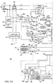
- Fig. 1 is an illustration of a telephone device 10 in which the present invention may be used.
- the telephone device 10 is coupled to a telephone line 12.
- the telephone line 12 conveys incoming telephone signals from and outgoing telephone signals to the commercial telephone network.
- the telephone signals may include signals representative of speech and signals representative of data.
- the telephone device 10 includes a base unit 14 and a handset 16 coupled to the base unit 14 by a cord 18.
- the base unit 14 includes a keypad 20 including a first plurality of keys.
- the base unit 14 preferably further includes a speakerphone speaker 22, a speakerphone microphone 24, and a speakerphone switch 26.
- the speakerphone switch 26 allows the user to selectively activate the speakerphone speaker 22 and the speakerphone microphone 24 for hands-free operation of the telephone device 10.
- the base unit 14 further includes function keypad 28, including a second plurality of keys. These keys may be independently programmed, for example, to cause the telephone device 10 to dial a predetermined number. Alternatively, where the telephone device 10 implements a digital answering machine, these keys may control the function of the digital answering machine, such as outgoing message recording and incoming message playback. Where the telephone device 10 implements a speakerphone, one or more of these keys may control a programmable attenuator for varying the volume of sound from the speakerphone speaker 22 or the sensitivity of the speakerphone microphone 24.
- the base unit 14 preferably further includes a display 30 and soft keys 32.
- the display may provide visual information to the user, such as date and time, the number dialed for an outgoing telephone call, or the origin of an incoming call.
- the display 30 may display information in accordance with the analog display services interface (ADSI) protocol.
- ADSI analog display services interface
- data is received over the telephone line 12, along with voice information.
- the data may be in the form of dual tone, multiple frequency (DTMF) tones.
- DTMF dual tone, multiple frequency
- the telephone device 10 may display a portion of the data on the display 30.
- the soft keys 32 may be programmable, producing an output the effect of which is determined by the received data.
- the telephone device 10 is preferably coupled to a line cord 33 for receiving alternating current (AC) power from a wall receptacle or other source.
- the AC power is converted to DC power for operating the telephone device 10.
- the telephone device 10 may preferably be powered by the operating voltage supplied on telephone line 12.
- the telephone device 10 preferably operates in any one of several operation modes. Active mode occurs whenever the telephone or answering machine functions are being used. When the telephone device 10 is not being actively used, it is in shutdown mode. In POTS ("plain old telephone service") mode, the telephone device 12 is powered by the telephone line 12. In in-circuit emulation mode, an external in-circuit emulator operates in place of the on-chip microcontroller.
- Active mode occurs whenever the telephone or answering machine functions are being used. When the telephone device 10 is not being actively used, it is in shutdown mode. In POTS ("plain old telephone service") mode, the telephone device 12 is powered by the telephone line 12. In in-circuit emulation mode, an external in-circuit emulator operates in place of the on-chip microcontroller.
- POTS plain old telephone service
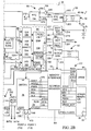
- the device 10 generally includes a telephone controller 38, a rectifier 40 and a loop hold circuit 42.
- the telephone device 10 further includes a voltage regulator 44, a hook switch 46, a transformer 48, a real-time clock crystal oscillator 50, a clock generator crystal oscillator 52, and an audio RAM 54.
- the telephone device 10 may also be coupled to other peripheral devices, such as the display 30 and soft keys 32.
- the telephone device 10 still further includes a handset earpiece 56 and a handset microphone 58 within the handset 16 and coupled to the telephone controller 38 by the cord 18.
- the telephone device 10 still further includes keypad 20, speakerphone speaker 22 and speakerphone microphone 24.
- the rectifier 40 and the voltage regulator 44 generate DC power to power the telephone device 10 in the event AC power is not available.
- the DC power is provided at the terminals 45 of the voltage regulator 44.
- the telephone controller 38 is preferably fabricated in a single integrated circuit.
- the telephone controller 38 preferably includes a ring detector 62, a real-time clock means 64, a battery monitor 66, a watchdog timer 68, a clock generator 70, a memory interface 72, a read-only memory 74, a microcontroller 76, an interrupt controller 78, a keypad scanner 80, tri-level inputs 82, a digital signal processor circuit 84, and an interface bus 86.
- the ring detector 62, the real-time clock means 64, the battery monitor 66, the watchdog timer 68, the clock generator 70, the memory interface 72, the microcontroller 76, the interrupt controller 78, the keypad scanner 80, the tri-level inputs 82, and the digital signal processor circuit 84 are all coupled to the interface bus 86 for conveying data and control signals.
- the telephone controller 38 further includes an output amplifier 88, coupled to outputs 90 and 92, and programmable attenuator 94 and switch 96.
- the switch 96 may be a CMOS transfer gate or other device for selectively coupling the programmable attenuator 94 to an output 98 of the digital signal processor circuit 84.
- the switch 96 is responsive to control signals provided by the microcontroller 76 over the interface bus 86. These control connections are not shown in Fig. 2 so as not to unduly complicate the drawing figure.
- the outputs 90 and 92 are coupled to the transformer 48, which is coupled to the telephone line 12 by the loop hold circuit 42.
- the output amplifier 88, the programmable attenuator 94 and the switch 96 form a telephone network transmitter means for transmitting outgoing electrical signals to the telephone network.
- the transformer 48 is also coupled to an input 100 of the telephone controller 38.
- a switch 102 is coupled to the input 100 for selectively coupling the input 105 of an input amplifier 104 to the input 100, responsive to a control signal received from the microcontroller 76.
- the input amplifier 104 is preferably an automatic gain control amplifier, and includes an input 108 for providing automatic gain control.
- a feedback network, including resistors or capacitors, for the automatic gain control amplifier 104 may be located off-chip, separate from the telephone controller 38.
- the telephone controller 38 may include additional input or output connections for coupling the feedback network to the input 108.
- the output 106 of the input amplifier 104 is coupled to an input 110 of the digital signal processor circuit 84.
- the switch 102 and the input amplifier 104 thus form a telephone network receiver means for receiving incoming electrical signals from the telephone network.
- the output 106 of the input amplifier 104 is also coupled to a switch 112.
- the switch 112 selectively couples the input amplifier 104 to a programmable attenuator 114, responsive to control signals received from the microcontroller 76.
- the programmable attenuator 114 is coupled to an output amplifier 116, which is coupled to outputs 118 and 120.
- the speakerphone speaker 22 is coupled to the outputs 118 and 120.
- the programmable attenuator 114 is also coupled to a switch 122, which selectively couples the programmable attenuator to the output 98 of the digital signal processor circuit 84, responsive to control signals received from the microcontroller 76.
- the programmable attenuator 114 is also connected to a switch 124, which selectively couples the programmable attenuator 114 to an output 126 of the digital signal processor circuit 84.
- the output amplifier 116, the programmable attenuator 114, the switch 122, the switch 112 and the switch 124 thus form speaker driver means for conveying speaker electrical signals to the speakerphone speaker.
- the telephone controller 38 further includes a microphone preamplifier 128.
- the microphone preamplifier 128 is coupled to inputs 130 and 132, which are coupled to the speakerphone microphone 24.
- the output 134 of the microphone preamplifier is coupled through a switch 136 to the input 105 of the input amplifier 104.
- the microphone preamplifier 128 and the switch 136 thus form a microphone receiver means for conveying microphone electrical signals from the speakerphone microphone to the telephone network transmitter means.
- the switch 136 also selectively couples the output 134 of the microphone preamplifier 128 to an input 154 of the digital signal processor circuit 84.
- the telephone controller 38 further includes an earpiece driver 138.
- the output of the earpiece driver 138 is coupled to an output 140.
- the handset earpiece 56 is coupled to the output 140.
- the telephone controller 38 further includes a microphone receiver 142 coupled to an input 144.
- the handset microphone 58 is coupled to the input 144.
- the output 146 of the microphone receiver 142 is coupled to a switch 148.
- the switch 148 selectively couples the output 146 of the microphone receiver 142 to the programmable attenuator 94 and to a sidetone generator 150.
- the sidetone generator 150 and a summer 152 combine electrical signals received from the handset microphone 58 with electrical signals received from the telephone line 12 by the input amplifier 104 and convey the signals to the earpiece driver 138. Addition of sidetone to incoming electrical signals is well known in the art for improving the comfort level of the user.
- the digital signal processor circuit 84 includes a single digital signal processor 154.
- the digital signal processor circuit 84 further includes a first digital-to-analog converter 156, a first analog-to-digital converter 158, a second digital-to-analog converter 160 and a second analog-to-digital converter 162.
- the microcontroller 76 is preferably an 80C51-type microcontroller.
- the 80C51 microcontroller is an industry standard microcontroller, well known in the art. An important advantage is provided by use of the 80C51 microcontroller. Since the 80C51 microcontroller is well known, the development of program instructions to control the microcontroller 76 and, in turn, to control the telephone controller 38, is simplified. This minimizes product development cost and time to market, both of which are important in the development of consumer products such as telephone devices.
- the microcontroller 76 may include a universal asynchronous receiver transmitter (UART) 164.
- the microcontroller 76 also includes a first port 166 and a second port 168. These ports are connected to ports 170 and 172, respectively, of the telephone controller 38.
- the first port 166 may serve as input and output pins for the universal asynchronous receiver transmitter 164.
- the microcontroller 76 is coupled to the memory interface 72 by a bus 176.
- the memory interface 72 couples the microcontroller 76 with the interface bus 86, with the audio RAM 54, the ROM 74 and with other peripheral devices, such as the display 30 and soft keys 32.
- the memory interface 72 also serves as a DRAM controller for the audio RAM 54.
- the memory interface is coupled to the audio RAM 54 by a memory bus 177.
- the audio RAM 54 preferably is a commercially available dynamic random access memory (DRAM) having a predetermined number of non-functioning storage locations, or bad bits. These bad bits may return a data value different from the value previously stored there.
- the data to be stored in the audio RAM 54 is digital data representative of speech, and is preferably compressed data. Since the data stored in the audio RAM 54 is decompressed upon playback, and since the bandwidth of telephone signals is narrow, some bad bits returning incorrect data will not significantly reduce audio quality upon playback.
- the use of audio-quality RAM for the audio RAM 54 provides a cost savings, in that a DRAM chip with some bad bits can be purchased at lower cost than a fully functional DRAM. This cost savings is important in the manufacture of consumer products, such as telephone devices.
- the digital signal processor circuit 84 performs speech compression and decompression, tone generation, speech synthesis, and detection of dual tone, multiple frequency (DTMF) tones.
- the digital signal processor 154 preferably operates responsive to a predetermined program of instructions.
- the program of instructions are preferably stored in a read-only memory 176.
- the microcontroller 76 handles the movement of data to and from the audio RAM 54 by means of the memory interface module 72.
- the analog-to-digital converter 158 receives audible inputs, including voice and tone inputs, from the telephone line 12.
- the second analog-to-digital converter 162 receives audible inputs from the speakerphone microphone 24.
- the first analog-to-digital converter 158 and the second analog-to-digital converter 162 convert speech in the form of analog electrical signals to digital data, in a manner well known in the art.
- the digital signal processor 154 compresses the digitized speech received from either the first analog-to-digital converter 158 or the second analog-to-digital converter 162 using an industry standard algorithm, for example, the VSELP (Vector Sum Excited Linear Prediction) algorithm.
- VSELP Vector Sum Excited Linear Prediction
- This algorithm is implemented as a predetermined program of instructions which control the digital signal processor 154.
- the audio RAM 54 consists of a single 4- megabit RAM chip, 10 to 15 minutes of record time may be achieved using the VSELP compression algorithm.
- the digital signal processor 154 receives over the interface bus 86 compressed data from the audio RAM 54.
- the compressed data are decompressed in accordance with an industry standard algorithm, for example, the VSELP algorithm.
- Decompressed data are supplied to the first digital-to-analog converter 156 or the second digital-to-analog converter 160.
- the first digital-to-analog converter 156 converts the digital data to analog signals representative of an audible output and provides the analog signals to switches 96 and 122. Responsive to control signals from the microcontroller 76, the switches convey the analog signals to the speakerphone speaker 22 or to the telephone line 12.
- the second digital-to-analog converter 160 converts digital data to analog signals representative of an audible output and provides the analog signals to switch 124, which conveys the analog signals to the speakerphone speaker 22.
- the read-only memory 136 preferably stores instructions for controlling the digital signal processor in implementing the algorithm for compression and decompression.
- the digital signal processor 154 preferably includes one or more tone generators 178.
- the tone generators 178 may provide DTMF tones, dial tones or busy tones. Where more than one tone generator is used, each tone generator preferably has an individually programmable amplitude output. These outputs may be summed together and provided to either the first digital-to-analog converter 156 or the second digital-to-analog converter 160, allowing for programmable twist.
- the digital signal processor 154 also includes a DTMF detector 180.
- the DTMF detector can operate simultaneously with the compression and expansion operation. This allows detection of DTMF tones during recording of an incoming message or during playback of an outgoing message when the telephone controller functions as a digital answering machine.
- the digital signal processor 154 still further includes a speech synthesizer 182. Synthesized speech may be used for automatically providing the time and date a message is recorded or for prompting the user.
- the speech synthesizer uses data stored in read-only memory 176 for synthesizing speech sounds.
- the keypad scanner 80 includes a plurality of inputs 184 and a plurality of outputs 186 for coupling to the keypad 20.
- the keypad scanner 80 When a key on the keypad 20 is depressed or released, the keypad scanner 80 generates an interrupt on the interface bus 86 to prompt the microcontroller 76 to interrogate the keypad scanner 80 to identify the depressed key.
- the keypad scanner 80 includes a keypad status register 184. When a key is depressed, the keypad scanner stores in the keypad status register a unique code identifying the depressed key. This code may be read over the interface bus 86 by the microcontroller 76 to determine which key was depressed and produce a suitable response.
- the ring detector 62 generates an interrupt signal on the interface bus 86 when a ring is detected on the telephone line 12.
- the ring detector 62 includes a tip/ring voltage analog-to-digital converter 190.
- the tip/ring voltage analog-to-digital converter 190 measures the potential difference between the tip conductor 34 and the ring conductor 36 and produces digital data representative of this potential difference.
- the digital data is supplied to the microcontroller 76 over the interface bus 86. From the digital data, the microcontroller can determine when an extension goes off-hook.
- the hook switch 46 indicates when the handset 16 has been lifted off-hook. When the handset is off-hook, tip 34 and ring 36 are coupled to form a loop, causing current to flow in the loop.
- the hook switch 46 provides a control signal at output 192. This control signal is preferably coupled to the port 172 of the telephone controller 38 for indicating to the microcontroller 76 when the telephone device 10 is off-hook.
- the loop hold circuit 42 functions to electronically lift the handset to connect the tip conductor 34 and the ring conductor 36.
- the telephone central office monitoring the telephone line 12, detects DC current flow through the tip 34 and ring 36 conductors and determines that the telephone device 10 is off-hook.
- the loop hold circuit 42 has a control output 194, which is preferably coupled to the port 172 of the telephone controller 38.
- the telephone device 10 When an incoming call is received by the telephone device 10, a ringing signal is detected by the ring detector circuit 62 and an interrupt is generated to the microcontroller 76. If the handset is lifted before a prescribed number of rings, the telephone device 10 operates as a telephone.
- the telephone line 12 is coupled through the loop hold circuit 42 to the transformer 48.
- Incoming electrical signals are received by the telephone controller 38 at input 100 and coupled through the switch 102 to the input amplifier 104.
- the input amplifier 104 provides the incoming electrical signals to the summer 152, which supplies the incoming signals plus a sidetone signal to the earpiece driver 138.
- the earpiece driver drives the handset earpiece 56, which produces an audible output.
- An audible input such as speech
- the microphone receiver 142 is coupled to the programmable attenuator 94 by the switch 148.
- the programmable attenuator 94 responds to control signals from the microcontroller 76 to selectively amplify or attenuate the outgoing electrical signals.
- the programmable attenuator 94 couples the outgoing electrical signals to the output amplifier 88 which conveys the outgoing electrical signals to the transformer 48 for coupling to the telephone line 12.
- the sidetone generator 150 couples a portion of the outgoing electrical signals received from the switch 148 to the summer 152.
- the telephone device 10 operates as a basic telephone under the control of the microcontroller 76.
- the hook switch 46 generates an interrupt at the output 192.
- the loop hold circuit 42 is activated to seize the loop.
- the user dials using the keypad, and in response to keypad activity, the microcontroller 76 establishes the appropriate signal path to place DTMF tones generated by the digital signal processor 154 on the telephone line 12, and to convey the DTMF tones to the earpiece 56.
- the microcontroller 76 directs the loop hold circuit 42 to release the loop.
- Ringing signals on the telephone line 12 are detected by the ring detector 62 which conveys an interrupt signal to the microcontroller 76. If the handset is not lifted before a prescribed number of rings, the unit operates as a digital answering machine.
- the microcontroller 76 provides a control signal to the loop hold circuit 42 to cause the loop hold circuit 42 to seize the loop.
- the memory interface 72 retrieves the compressed digital outgoing message from the audio RAM 54 and conveys it to the digital signal processor 154.
- the digital signal processor 154 decompresses the compressed digital outgoing message to produce a digital outgoing message, and conveys the digital outgoing message to the first digital-to-analog converter 156.
- the first digital-to-analog converter 156 converts the digital outgoing message to electrical signals representative of speech.
- the switch 96 couples the first digital-to-analog converter 156 to the programmable attenuator 94, which conveys the electrical signals to the output amplifier 88, which conveys the outgoing message to the telephone line.
- the tone generator 178 in the digital signal processor 154 After the outgoing message is played, the tone generator 178 in the digital signal processor 154 generates a beep tone that is routed to the telephone line to indicate that the user may begin recording an incoming message.
- the audible input forming the incoming message is conveyed from the telephone line 12 through the loop hold circuit 42 to the transformer 48 and conveyed to the input 100.
- the switch 102 couples the input 100 to the input amplifier 104 which conveys the incoming message to the first analog-to-digital converter 158.
- the first analog-to-digital converter converts the electrical signals representative of the audible input to digital data representative of the audible input and conveys the digital data to the digital signal processor 154.
- the digital signal processor compresses the digital data to produce a compressed digital incoming message.
- the memory interface 72 receives the compressed digital incoming message from the digital signal processor 154 and stores the compressed digital incoming message in the audio RAM 54.
- the speech synthesizer 182 may provide a time and date stamp with the digital incoming message which is also compressed and stored with the compressed digital incoming message in the audio RAM 54.
- the operation of the telephone device 10 in a remote message playback and DTMF detection mode will now be described.
- the user is listening to a recorded message from a remote telephone.
- the incoming call is answered by the telephone device 10 as described above.
- the caller may input DTMF tones indicating that the caller wishes to listen to stored messages.
- the DTMF tones are received from the telephone line at the input 100, coupled through the switch 102 to the input amplifier 104 and conveyed to the analog-to-digital converter 158.
- the digital signal processor 154 receives the DTMF tones and the DTMF detector 180 detects the DTMF tones and converts them to digital data.
- the digital signal processor 154 conveys the digital data to the memory interface 72.
- the DTMF tones may form a predetermined code to which the microcontroller 76 responds by playing back a recorded message.
- the user is listening to a recorded message.
- a message playback switch which may be part of the function keypad 28 of the base unit 14 (Fig. 1).
- the message playback switch generates an interrupt to the microcontroller 76.
- the memory interface 72 conveys the compressed digital incoming message from the audio RAM 54 to the digital signal processor 154.
- the digital signal processor 154 decompresses the compressed digital incoming message to produce digital data and conveys the digital data to the second digital-to-analog converter 160.
- the second digital-to-analog converter 160 converts the digital data to electrical signals representative of an audible output.
- the switch 124 couples the second digital-to-analog converter 160 to the programmable attenuator 114.
- the programmable attenuator 114 may be responsive to control signals received from the microcontroller 76 for amplifying or attenuating the electrical signals.
- the microcontroller 76 may respond to the depressing of one or more keys on the function keypad 28, for example, to adjust the volume or tone of the electrical signals.
- the programmable attenuator 114 conveys the electrical signals to the output amplifier 116 for playing the message to the speakerphone speaker 22.
- the user is recording the message that will be played out over the telephone line when the telephone device 10 operates in answering machine mode.
- the user presses and holds an outgoing message record switch, which may be located on the function keypad 28.
- an interrupt is generated to the microcontroller.
- An audible input such as speech, is received by the speakerphone microphone 24 and converted to electrical signals representative of the audible input.
- the electrical signals are coupled by the microphone preamplifier 128 through the switch 136 to the second analog-to-digital converter 162.
- the second analog-to-digital converter 162 converts the electrical signals to digital data representative of an audible input and conveys digital data to the digital signal processor 154.
- the digital signal processor 154 compresses the digital signals to produce a compressed digital outgoing message.
- the digital signal processor 154 conveys the compressed digital outgoing message over the interface bus 86 to the memory interface 72, which stores the compressed digital outgoing message in the audio RAM 54.
- the telephone device 10 receives over the telephone line 12 ADSI data for display on the display 30 (Fig. 1).
- the telephone device 10 may also receive voice information as well.
- the soft keys 32 may be used for data entry, the data being conveyed over the telephone line to a remote location.
- the ADSI data is received at the input 100 and conveyed through the switch 102 to the input amplifier 104.
- the input amplifier 104 conveys the data to the first analog-to-digital converter 158 where the data is converted from electrical signals representative of an audible input to digital data representative of an audible input.
- the analog-to-digital converter 158 conveys the digital data to the digital signal processor 154, where the DTMF detector 180 detects the DTMF tones which form the data.
- the digital data is conveyed over the interface bus 86 to the memory interface 72.
- the microcontroller 76 may respond to the data by displaying a portion of the data on the display 30.
- the microcontroller 76 may also respond to the data by storing a portion of the data in the audio RAM 54. Still further, the microcontroller 76 may respond to the data by programming the soft keys 32.
- the soft keys 32 are preferably a plurality of programmable keys which produce a plurality of output signals.
- the microcontroller 76 programs the programmable keys, the microcontroller 76 establishes a plurality of predetermined responses, each predetermined response of the plurality of predetermined responses corresponding to one output signal of the plurality of output signals.
- One or more of the responses of the plurality of predetermined responses may correspond to conveying data from the telephone controller 38 to the telephone line 12. In that case, the data are conveyed from the memory interface 72 over the interface bus 86 to the digital signal processor 154.
- the tone generator 178 of the digital signal processor 154 generates DTMF tones corresponding to the data to be conveyed to the telephone line 12.
- the digital signal processor 154 conveys the tone data to the first digital-to-analog converter 156.
- the first digital-to-analog converter 156 converts the digital data to electrical signals representative of an audible output and conveys the electrical signals through the switch 96 to the programmable attenuator 94, which conveys the signals through the output amplifier 88 to the telephone line 12.
- a telephone controller embodying the present invention includes several features which enhance the convenience and robustness of the system.
- the telephone controller 38 includes a real-time clock means 64.
- the real-time clock means operates from the normal supply voltage for the telephone controller 38 when the telephone controller receives the supply voltage.
- the real-time clock means operates from a dedicated battery when power is removed from the telephone controller.
- the clock input to the real-time clock means comes from either the 60 Hz AC power received from the power line cord 33 coupled to the telephone device 10 or from a crystal oscillator, preferably having an oscillation frequency of 262.144 KHz.
- the crystal oscillator provides timing for the DRAM controller function of the memory interface module 72 when the telephone controller 38 is in shutdown mode, that is, when the telephone and answering machine are not being actively used.
- the real-time clock means 64 includes a real-time clock generator 194, a line frequency receiver 196 and a real-time clock oscillator 198.
- the line frequency receiver 196 has an input 200 coupled to an input 202 of the telephone controller 38 for receiving the 60 Hz power line frequency from the line cord 33.
- the real-time clock oscillator 198 is coupled to inputs 203 of the telephone controller 38 for receiving oscillator signals from the real-time clock crystal oscillator 50, located off-chip from the telephone controller 38.
- the real-time clock generator 194 operates in response to a 1 Hz clock received at either input 206, from the line frequency receiver 196, or at input 208, from the real-time clock oscillator 198.
- the real-time clock generator 194 has a port 210 coupled to the interface bus 86.
- the real-time clock generator 194 preferably provides the year, the month, hours, minutes and seconds, with data reported in either binary or binary coded decimal.
- the time and date can be initialized through software writes to the real-time clock generator 194, over the interface bus 86 to the port 210.
- the real-time clock generator 194 updates the time and date once each second, in response to the 1 Hz clock signals received at either input 206 or input 208.
- the current time and date can be read from the real-time clock generator 194 over the interface bus 86.
- the real-time clock generator 194 also has an interrupt output 212 for providing interrupt signals to the interrupt controller 78.
- the battery monitor 66 is coupled to an input 214 of the telephone controller 38.
- the input 214 is adapted to be coupled to a depletable energy source, such as battery 51.
- the battery monitor 66 preferably includes an analog-to-digital converter 216 for detecting the battery voltage received at the input 214 and converting the received voltage to a digital value.
- the battery monitor 66 further includes a port 217 for supplying the digital value representative of the detected battery voltage to the interface bus 86.
- the microcontroller 76 can receive the digital value over the interface bus 86 for monitoring the voltage level of the battery.
- the analog-to-digital converter 216 is preferably a 4-bit analog-to-digital converter.
- the robustness of the telephone controller 38 is further enhanced by the watchdog timer 68.
- the watchdog timer 68 provides a measure of system integrity by detecting if the program instructions which control the microcontroller 76 become hung up or lost. If such a condition is detected, the watchdog timer 68 generates a hardware reset to the telephone controller 38 as well as the rest of the telephone device 10. Preferably, a hardware reset is generated if an internal counter within the watchdog timer68 is not cleared approximately every 2 seconds. The counter is cleared by the microcontroller 76 writing a specific code sequence to a register 218 within the watchdog timer 68.
- the watchdog timer 68 includes a port 220 coupled to the interface bus 186 and an output coupled to the reset output 222 of the telephone controller 38.
- the watchdog timer 68 generates a reset signal in the form of a pulse at the reset output 222 if the watchdog timer 68 times out.
- the reset signal causes the telephone controller 38 to return to a predetermined condition.
- the timeout value is preferably approximately 2 seconds.
- a specific key sequence must be written by the microcontroller 76 to the watchdog timer register 218 within this 2 second interval following a reset condition, and within a 2 second interval following the previous update, to prevent timeout.
- the key sequence is a 2-stage function starting from reset.
- the watchdog timer 86 starts in stage 1, waiting for a write to the watchdog timer register 218. If the value written by the microcontroller 76 to the watchdog timer register 218 is anything but a predetermined value, such as hexadecimal value A5, a system reset is generated by the watchdog timer 68 at the output 222. If the value written to the watchdog timer register 218 was the predetermined value, such as hexadecimal value A5, stage 2 is entered. In stage 2, the watchdog timer waits for another write to the watchdog timer register 218.
- the timer 68 is reset and stage 1 is re-entered. If the write is something other than the second predetermined value, a system reset is generated at the output 222.
- the clock generator 70 is coupled to clock generator inputs 224 for receiving clocking signals from the clock generator crystal oscillator 52. In response to these received clocking signals, the clock generator 70 generates system clock signals.
- the clock generator 70 includes an output 226 coupled to the memory interface 72 for providing clocking signals to the memory interface 72.
- the clock generator 70 further includes a port 228 coupled to the interface bus 86 for communicating with the microcontroller 76.
- the microcontroller can select the frequency of the system clock signals generated by the clock generator 70 by appropriate communications over the interface bus 86. The microcontroller can shut down the clock generator 70 to place the telephone controller 38 in shutdown mode to conserve power.
- the interrupt controller 78 functions to gather interrupt requests from the various interrupt sources, internal and external to the telephone controller 38, and to generate an interrupt to the microcontroller 76.
- the interrupt controller 78 includes a plurality of inputs 230 coupled to other elements of the telephone controller 38, such as the keypad scanner 80, the ring detector 62 and the real-time clock means 64. In response to an interrupt received at one of the inputs 230, the interrupt controller 78 stores a value in register 234 indicating the source of the interrupt.
- the interrupt controller 78 further includes outputs 232 coupled to the microcontroller 76 for indicating to the microcontroller 76 the existence of an interrupt condition. In response to the indication of an interrupt condition, the microcontroller 76 reads the contents of the interrupt status register 234 over the interface bus 86 to determine the source of the interrupt.
- the tri-level inputs 82 includes a first input 236 and a second input 238. These inputs can detect three distinct input states, high, low and open circuit. The detected state of each of the inputs is reported by the tri-level input circuit 82 to the interrupt controller 78.
- one of the inputs 236 or 238 could be coupled to a ringer switch on the telephone device 10, to select ringer volume level including high, low and off settings.
- input 238 could be coupled to a switch within the telephone device 10 which selects the predetermined number of rings provided by the telephone device 10 before an incoming call is automatically answered by the telephone device 10.
- a telephone device 10 embodying the present invention is further enhanced by the provision of a number of operating modes for the telephone controller 38. These include an active mode, plain old telephone service or POTS mode, shutdown mode, in-circuit emulation mode, and off-chip ROM mode.
- the telephone controller 38 is in active mode any time the clock generator 70 is running. Active mode is used whenever the telephone device 10 functions as a telephone or answering machine. In active mode, all functional blocks of the telephone controller 38 may be used to their full capacity.
- the telephone controller preferably includes several features designed to further reduce power consumption of the telephone.
- all of the functional blocks of the telephone controller 38 such as the rind detect 62, the real-time clock means 64, the battery monitor 66, the watchdog timer 68, the clock generator 70, the keypad scanner 80 and the digital signal processor circuit 84, can be activated and deactivated by software commands controlling the microcontroller 76.
- the frequency of the clock signals generated by the clock generator 70 can be varied. Slower clock signals correspond to reduced power consumption.
- the clock generator can also be turned off completely.
- the clock generator 70 can be sped up automatically whenever an interrupt is received by the microcontroller 76. This allows for very low clock rates when no activity is occurring without sacrificing interrupt response time.
- POTS mode is a special case of active mode, in which the clock generator 70 is on but the digital signal processor circuit 84 is clocked at a slow rate.
- POTS mode allows the telephone controller 38 to provide basic POTS functions by powering the telephone device 10 from the telephone line 12 if the AC power fails.
- the earpiece driver 138, the microphone receiver 142, the sidetone generator 150, keypad scanner 80 and parallel ports 166 and 168 are active, the digital signal processor circuit 84 operates at a slow clock rate to provide DTMF dialing tones, and the microcontroller 76 is active at a slow clock rate to provide keypads, pulse dialing and other control functions. Answering machine functions are disabled in this mode.
- Shutdown mode is the normal state that the telephone controller 38 is placed in when the telephone and answering machine functions are not being actively used. In shutdown mode, only the real-time clock means 64 and the DRAM refresh function of the memory interface 72 remain powered. Shutdown mode can be terminated by an external interrupt, such as keypad activity or ring detect, or by an interrupt from the real-time clock means 64.
- In-circuit emulation mode allows an external in-circuit emulator to control operation of the telephone controller 38 in place of the on-chip microcontroller 76.
- the microcontroller 76 is deactivated and the external in-circuit emulator controls the operation of the telephone controller 38. This mode is useful for writing and testing software instructions for use in controlling the microcontroller 76.
- Off-chip ROM mode allows the microcontroller 76 to operate responsive to program instructions and data stored in an external memory device rather than instructions stored in the ROM 74.
- a telephone controller for controlling operation of a telephone using a single digital signal processor to provide functions including a digital answering machine, a telephone, a speakerphone and compatibility with the analog display services interface.
- the telephone controller is integrated within a single integrated circuit.
- the single integrated circuit thus integrates both digital control functions as well as analog telephone line interface functions.
- Use of a single digital signal processor and integration within a single integrated circuit reduces cost of the telephone controller, reduces noise on analog signal paths and subsequent inaccuracies in digital signals, requires fewer components and interconnections and reduces power consumption.
Landscapes
- Engineering & Computer Science (AREA)
- Signal Processing (AREA)
- Computer Hardware Design (AREA)
- Microelectronics & Electronic Packaging (AREA)
- Telephone Function (AREA)
Applications Claiming Priority (2)
| Application Number | Priority Date | Filing Date | Title |
|---|---|---|---|
| US08/185,697 US5483577A (en) | 1994-01-24 | 1994-01-24 | Single chip telephone answering machine, telephone, speakerphone, and ADSI controller |
| US185697 | 1994-01-24 |
Publications (2)
| Publication Number | Publication Date |
|---|---|
| EP0664632A2 true EP0664632A2 (fr) | 1995-07-26 |
| EP0664632A3 EP0664632A3 (fr) | 1999-07-14 |
Family
ID=22682082
Family Applications (1)
| Application Number | Title | Priority Date | Filing Date |
|---|---|---|---|
| EP95300280A Withdrawn EP0664632A3 (fr) | 1994-01-24 | 1995-01-18 | Unité de commande d'un poste téléphonique |
Country Status (3)
| Country | Link |
|---|---|
| US (1) | US5483577A (fr) |
| EP (1) | EP0664632A3 (fr) |
| JP (1) | JPH07303128A (fr) |
Cited By (4)
| Publication number | Priority date | Publication date | Assignee | Title |
|---|---|---|---|---|
| WO1998014023A1 (fr) * | 1996-09-25 | 1998-04-02 | Advanced Micro Devices, Inc. | Architecture de systeme numerique configurable de communications sans fil et cable |
| WO1999017516A1 (fr) * | 1997-09-29 | 1999-04-08 | Siemens Aktiengesellschaft | Circuit de commutation integre pour appareil radio mobile possedant une fonction de repondeur telephonique |
| EP1211874A2 (fr) * | 2000-12-01 | 2002-06-05 | Hitachi Micro Systems Europe Limited | Dispositif semiconducteur monopuce pour réaliser la fonction d'effet local dans un téléphone |
| WO2007073589A2 (fr) * | 2005-12-29 | 2007-07-05 | Leonardo Senna Da Silva | Systeme de numerotation automatique permettant de rechercher un contact dans une base de donnees stockee dans un ordinateur personnel |
Families Citing this family (54)
| Publication number | Priority date | Publication date | Assignee | Title |
|---|---|---|---|---|
| US5636270A (en) * | 1993-12-30 | 1997-06-03 | Davey; Melville G. | Method of producing signals commonly used with telephones |
| US5675633A (en) * | 1994-07-20 | 1997-10-07 | Alcatel N.V. | Digital telephone answering set |
| US5652903A (en) * | 1994-11-01 | 1997-07-29 | Motorola, Inc. | DSP co-processor for use on an integrated circuit that performs multiple communication tasks |
| US6041118A (en) * | 1994-12-22 | 2000-03-21 | Lucent Technologies Inc. | Architecture for telephone set |
| DE4446507A1 (de) * | 1994-12-24 | 1996-06-27 | Sel Alcatel Ag | Digitales Telefon |
| JP2928754B2 (ja) * | 1995-02-22 | 1999-08-03 | 三星電子株式会社 | 電話機能付きコンピュータ接続装置 |
| JP3550207B2 (ja) * | 1995-03-01 | 2004-08-04 | 富士通株式会社 | モード切替え式電話機及び同電話機におけるモード設定方法 |
| DE19511622A1 (de) * | 1995-03-30 | 1996-10-02 | Michael Wolf | Türrufbeantworter |
| JPH08279845A (ja) * | 1995-04-06 | 1996-10-22 | Sony Corp | 留守番電話機 |
| US5687227A (en) * | 1995-05-25 | 1997-11-11 | Lucent Technologies, Inc. | Telephone with user recorded ringing signal |
| US5649005A (en) * | 1995-07-07 | 1997-07-15 | Northern Telecom Limited | PC with telephony exchange function |
| US5790656A (en) * | 1995-09-29 | 1998-08-04 | Rockwell International Corporation | Data access arrangement with telephone interface |
| US5708698A (en) * | 1995-10-10 | 1998-01-13 | Sony Corporation | Method for trimming and/or replacing a portion of a received voice message |
| US5867575A (en) * | 1995-10-20 | 1999-02-02 | Creative Technology Ltd. | Optimized interface between audio/modem board and sound board |
| US5737394A (en) * | 1996-02-06 | 1998-04-07 | Sony Corporation | Portable telephone apparatus having a plurality of selectable functions activated by the use of dedicated and/or soft keys |
| US5819069A (en) | 1996-02-27 | 1998-10-06 | Nexcom Technology, Inc. | Recording apparatus and method having low power consumption |
| US5809111A (en) * | 1996-04-01 | 1998-09-15 | Matthews Communications Management, Inc. | Telephone control module and user site network and methods of operation |
| JP3092053B2 (ja) * | 1996-05-28 | 2000-09-25 | 松下電器産業株式会社 | 電話機における記録再生装置 |
| US5781564A (en) * | 1996-06-05 | 1998-07-14 | Thomson Consumer Electronics, Inc. | Method and apparatus for detecting and concealing data errors in stored digital data |
| US6252944B1 (en) | 1997-06-11 | 2001-06-26 | Estech Systems, Inc. | Telephone call/voice processing system |
| US7421066B1 (en) * | 1996-06-12 | 2008-09-02 | Estech Systems, Inc. | Telephone call/voice processing system |
| US5970122A (en) * | 1996-07-24 | 1999-10-19 | Lucent Technologies Inc. | Two-way wireless messaging system having user agent |
| US5825852A (en) | 1996-07-24 | 1998-10-20 | Notify Corporation | Multisensing circuitry for class signals and stutter dial tone in visual message waiting indicator |
| US6269152B1 (en) * | 1996-08-02 | 2001-07-31 | Kenneth A. Jursinski | Telephone annunciator |
| US5991366A (en) * | 1996-11-07 | 1999-11-23 | Lucent Technologies Inc. | Telephone information retrieval system |
| TW317403U (en) * | 1996-11-11 | 1997-10-01 | Winbond Electronics Corp | Telephone device capable of saying identification number |
| US5796815A (en) * | 1996-12-05 | 1998-08-18 | Advanced Micro Devices, Inc. | Communications device with improved ring signal detection |
| US5949852A (en) * | 1996-12-20 | 1999-09-07 | At&T Corp | Method for recording messages for absent parties |
| WO1998028894A1 (fr) * | 1996-12-23 | 1998-07-02 | Mci Communications Corporation | Systeme et procede visant a modifier des signaux vocaux en vue d'eviter le declenchement de detecteurs de tonalite |
| GB2320845B (en) * | 1996-12-30 | 2001-07-25 | Inventec Corp | Method of recording the communication between a CPE and a SPCS/server |
| US5983284A (en) * | 1997-01-10 | 1999-11-09 | Lucent Technologies Inc. | Two-button protocol for generating function and instruction messages for operating multi-function devices |
| JPH10210139A (ja) * | 1997-01-20 | 1998-08-07 | Sony Corp | 音声記録機能付き電話装置及び音声記録機能付き電話装置の音声記録方法 |
| US6337898B1 (en) * | 1997-04-22 | 2002-01-08 | Nortel Networks Limited | Method for monitoring voicemail calls using ADSI capable CPE |
| US5901217A (en) * | 1997-06-05 | 1999-05-04 | Kanbar; Maurice S. | Electronic telephone directory dialer module |
| US6940962B1 (en) | 1997-06-11 | 2005-09-06 | Estech Systems, Inc. | Dial on-hold |
| US6968065B1 (en) * | 1997-09-24 | 2005-11-22 | Sandisk Corporation | Multiple function, bi-directional input/output interface for sound processing system |
| JPH11143500A (ja) * | 1997-11-05 | 1999-05-28 | Sony Corp | Ic記録再生機 |
| US6292543B1 (en) | 1998-01-16 | 2001-09-18 | Lucent Technologies Inc. | Apparatus and method which saves call related information when the status of recorded voice message is changed remotely |
| US6349133B1 (en) | 1998-04-15 | 2002-02-19 | Premisenet Incorporated | Method and system for interfacing a telephony network and a digital data stream |
| US6643358B2 (en) * | 1998-05-27 | 2003-11-04 | 3Com Corporation | Telephone answering apparatus and method for confirming an acoustic command signal |
| US6208714B1 (en) * | 1998-06-02 | 2001-03-27 | 3Com Corporation | Telephone answering apparatus for indicating the presence of a power cycle |
| US6208716B1 (en) * | 1998-06-02 | 2001-03-27 | 3Com Corporation | Telephone answering apparatus and method for determining the time of message reception |
| KR100275952B1 (ko) * | 1998-06-24 | 2000-12-15 | 김영환 | 유선통신장치 자동응답 시스템 |
| US6535583B1 (en) * | 1998-08-26 | 2003-03-18 | Nortel Networks Limited | Voice recompression method and apparatus |
| US6347133B1 (en) * | 1998-12-23 | 2002-02-12 | John Alexander Galbreath | Telephone answering device with timer control |
| KR100322003B1 (ko) * | 1998-12-30 | 2002-05-13 | 윤종용 | 휴대용무선전화기의음성메모재생방법 |
| US7558381B1 (en) * | 1999-04-22 | 2009-07-07 | Agere Systems Inc. | Retrieval of deleted voice messages in voice messaging system |
| US7530070B1 (en) * | 2000-08-10 | 2009-05-05 | Agere Systems Inc. | Dynamically configurable architecture for mixed data processing |
| US6899273B2 (en) * | 2001-05-02 | 2005-05-31 | Hand Held Products, Inc. | Optical reader comprising soft key including permanent graphic indicia |
| US20030179860A1 (en) * | 2002-03-22 | 2003-09-25 | Multisuns Corp. | Apparatus and method for recording meeting and/or teleconference |
| US6714630B1 (en) * | 2002-05-23 | 2004-03-30 | Uniden America Corporation | System and method for screening calls |
| JP2004159284A (ja) * | 2002-09-10 | 2004-06-03 | Matsushita Electric Ind Co Ltd | 無線通信装置および受信方式選択方法 |
| JP2012080161A (ja) * | 2010-09-30 | 2012-04-19 | Icom Inc | 送信機およびコンピュータプログラム |
| US8458533B2 (en) * | 2010-11-03 | 2013-06-04 | Texas Instruments Incorporated | Watch dog timer and counter with multiple timeout periods |
Citations (2)
| Publication number | Priority date | Publication date | Assignee | Title |
|---|---|---|---|---|
| EP0465054A1 (fr) * | 1990-07-06 | 1992-01-08 | Advanced Micro Devices, Inc. | Processeur de communication |
| US5199064A (en) * | 1990-12-03 | 1993-03-30 | Advanced Micro Devices, Inc. | Fully-integrated telephone unit |
Family Cites Families (1)
| Publication number | Priority date | Publication date | Assignee | Title |
|---|---|---|---|---|
| US5329579A (en) * | 1992-07-27 | 1994-07-12 | At&T Bell Laboratories | Modular adjunct processor made of identical multi-function modules adaptable under direction of one of them to perform any of the adjunct-processor functions |
-
1994
- 1994-01-24 US US08/185,697 patent/US5483577A/en not_active Expired - Lifetime
-
1995
- 1995-01-18 EP EP95300280A patent/EP0664632A3/fr not_active Withdrawn
- 1995-01-23 JP JP7008180A patent/JPH07303128A/ja not_active Withdrawn
Patent Citations (2)
| Publication number | Priority date | Publication date | Assignee | Title |
|---|---|---|---|---|
| EP0465054A1 (fr) * | 1990-07-06 | 1992-01-08 | Advanced Micro Devices, Inc. | Processeur de communication |
| US5199064A (en) * | 1990-12-03 | 1993-03-30 | Advanced Micro Devices, Inc. | Fully-integrated telephone unit |
Non-Patent Citations (2)
| Title |
|---|
| FELDMANN J: "ALLROUND-CHIP MIT SPRACHFUNKTION" FUNKSCHAU, vol. 64, no. 3, 24 January 1992, pages 68-73, XP000304990 * |
| YUTAKA NISHINO ET AL: "AN ISDN BASIC FEATURE TELEPHONE SET" NTT REVIEW, vol. 3, no. 2, 1 March 1991, pages 89-97, XP000230759 * |
Cited By (6)
| Publication number | Priority date | Publication date | Assignee | Title |
|---|---|---|---|---|
| WO1998014023A1 (fr) * | 1996-09-25 | 1998-04-02 | Advanced Micro Devices, Inc. | Architecture de systeme numerique configurable de communications sans fil et cable |
| WO1999017516A1 (fr) * | 1997-09-29 | 1999-04-08 | Siemens Aktiengesellschaft | Circuit de commutation integre pour appareil radio mobile possedant une fonction de repondeur telephonique |
| EP1211874A2 (fr) * | 2000-12-01 | 2002-06-05 | Hitachi Micro Systems Europe Limited | Dispositif semiconducteur monopuce pour réaliser la fonction d'effet local dans un téléphone |
| EP1211874A3 (fr) * | 2000-12-01 | 2003-01-22 | Hitachi Micro Systems Europe Limited | Dispositif semiconducteur monopuce pour réaliser la fonction d'effet local dans un téléphone |
| WO2007073589A2 (fr) * | 2005-12-29 | 2007-07-05 | Leonardo Senna Da Silva | Systeme de numerotation automatique permettant de rechercher un contact dans une base de donnees stockee dans un ordinateur personnel |
| WO2007073589A3 (fr) * | 2005-12-29 | 2008-07-31 | Leonardo Senna Da Silva | Systeme de numerotation automatique permettant de rechercher un contact dans une base de donnees stockee dans un ordinateur personnel |
Also Published As
| Publication number | Publication date |
|---|---|
| EP0664632A3 (fr) | 1999-07-14 |
| JPH07303128A (ja) | 1995-11-14 |
| US5483577A (en) | 1996-01-09 |
Similar Documents
| Publication | Publication Date | Title |
|---|---|---|
| US5483577A (en) | Single chip telephone answering machine, telephone, speakerphone, and ADSI controller | |
| US6377663B1 (en) | Call management system and associated method for a local telephone circuit | |
| GB2328835A (en) | Remote access to telephone numbers stored in a telephone set | |
| US5696813A (en) | Telephone set | |
| US5235635A (en) | Keypad monitor with keypad activity-based activation | |
| US6973179B1 (en) | Pocket speakerphone | |
| JP4059530B2 (ja) | ボタン電話装置 | |
| KR100330081B1 (ko) | 컴퓨터를 이용한 통화음 녹음장치와 그 제어방법 | |
| KR20020057084A (ko) | 통화 기능을 구비한 사운드 카드 | |
| JP3513789B2 (ja) | 電話機 | |
| KR0172076B1 (ko) | 전화기를 이용한 가전제품의 연동장치 | |
| KR100191342B1 (ko) | 전화기의 예약시각 자동 알람방법 | |
| JPH087713Y2 (ja) | ディジタル電話機の着信音発生回路 | |
| KR100188855B1 (ko) | 전화기용 외부확장 음성메모리장치와 이를 운용하는 전화 시스템 | |
| JP2514361B2 (ja) | ボタン電話装置の留守応答方式 | |
| KR200171096Y1 (ko) | 경박형 전화기 | |
| KR0158313B1 (ko) | 통화내용저장기능을 갖춘 확장메모리장치와 이를 운용하는 전화 시스템 | |
| KR0143813B1 (ko) | 통화가 가능한 입력장치 | |
| KR200164445Y1 (ko) | 전화음성처리장치 | |
| KR930009305A (ko) | 다기능 음성 우편 전화기 | |
| KR20010066561A (ko) | 일반전화와 화상전화의 전환장치 | |
| JPH0413341A (ja) | コードレス親子電話装置 | |
| KR20030012186A (ko) | 전화기 벨소리 및 통화대기음 출력장치 | |
| JPS61284155A (ja) | 多機能電話機 | |
| JPS63171048A (ja) | デイジタル電話機回路 |
Legal Events
| Date | Code | Title | Description |
|---|---|---|---|
| PUAI | Public reference made under article 153(3) epc to a published international application that has entered the european phase |
Free format text: ORIGINAL CODE: 0009012 |
|
| AK | Designated contracting states |
Kind code of ref document: A2 Designated state(s): AT BE DE DK ES FR GB GR IE IT LU NL PT SE |
|
| PUAL | Search report despatched |
Free format text: ORIGINAL CODE: 0009013 |
|
| AK | Designated contracting states |
Kind code of ref document: A3 Designated state(s): AT BE DE DK ES FR GB GR IE IT LU NL PT SE |
|
| RIC1 | Information provided on ipc code assigned before grant |
Free format text: 6H 04M 1/00 A, 6H 04M 1/65 B, 6H 04M 1/60 B |
|
| STAA | Information on the status of an ep patent application or granted ep patent |
Free format text: STATUS: THE APPLICATION IS DEEMED TO BE WITHDRAWN |
|
| 18D | Application deemed to be withdrawn |
Effective date: 20000115 |