EP0664463A1 - Grundmaterial für optische fasern aus kunststoff, sowie verfahren und vorrichtung zu dessen herstellung - Google Patents
Grundmaterial für optische fasern aus kunststoff, sowie verfahren und vorrichtung zu dessen herstellung Download PDFInfo
- Publication number
- EP0664463A1 EP0664463A1 EP94917812A EP94917812A EP0664463A1 EP 0664463 A1 EP0664463 A1 EP 0664463A1 EP 94917812 A EP94917812 A EP 94917812A EP 94917812 A EP94917812 A EP 94917812A EP 0664463 A1 EP0664463 A1 EP 0664463A1
- Authority
- EP
- European Patent Office
- Prior art keywords
- refractive index
- optical fiber
- preform
- polymer
- plastic optical
- Prior art date
- Legal status (The legal status is an assumption and is not a legal conclusion. Google has not performed a legal analysis and makes no representation as to the accuracy of the status listed.)
- Withdrawn
Links
- 239000013308 plastic optical fiber Substances 0.000 title claims abstract description 114
- 239000000463 material Substances 0.000 title claims abstract description 66
- 238000004519 manufacturing process Methods 0.000 title description 33
- 229920000642 polymer Polymers 0.000 claims abstract description 100
- 238000000576 coating method Methods 0.000 claims abstract description 41
- 238000005229 chemical vapour deposition Methods 0.000 claims abstract description 22
- 239000003795 chemical substances by application Substances 0.000 claims abstract description 7
- 239000003607 modifier Substances 0.000 claims description 91
- 238000000034 method Methods 0.000 claims description 83
- 239000013307 optical fiber Substances 0.000 claims description 79
- 230000008569 process Effects 0.000 claims description 71
- 238000005253 cladding Methods 0.000 claims description 61
- 238000009826 distribution Methods 0.000 claims description 61
- 238000000151 deposition Methods 0.000 claims description 58
- 230000008021 deposition Effects 0.000 claims description 52
- 239000002994 raw material Substances 0.000 claims description 39
- 238000010438 heat treatment Methods 0.000 claims description 37
- 238000002156 mixing Methods 0.000 claims description 28
- 238000005507 spraying Methods 0.000 claims description 18
- 230000003247 decreasing effect Effects 0.000 claims description 16
- 238000002844 melting Methods 0.000 claims description 16
- 230000008018 melting Effects 0.000 claims description 16
- 229920000620 organic polymer Polymers 0.000 claims description 14
- 238000000149 argon plasma sintering Methods 0.000 claims description 6
- 239000006096 absorbing agent Substances 0.000 claims description 5
- 239000003963 antioxidant agent Substances 0.000 claims description 5
- 230000003078 antioxidant effect Effects 0.000 claims description 5
- 235000006708 antioxidants Nutrition 0.000 claims description 5
- 238000001947 vapour-phase growth Methods 0.000 claims description 4
- 229920003023 plastic Polymers 0.000 abstract description 8
- 239000004033 plastic Substances 0.000 abstract description 8
- 230000007423 decrease Effects 0.000 abstract description 4
- 239000010410 layer Substances 0.000 description 137
- 239000000835 fiber Substances 0.000 description 70
- 230000005540 biological transmission Effects 0.000 description 58
- 238000012681 fiber drawing Methods 0.000 description 53
- 239000011162 core material Substances 0.000 description 50
- WYURNTSHIVDZCO-UHFFFAOYSA-N Tetrahydrofuran Chemical compound C1CCOC1 WYURNTSHIVDZCO-UHFFFAOYSA-N 0.000 description 26
- IRIAEXORFWYRCZ-UHFFFAOYSA-N Butylbenzyl phthalate Chemical compound CCCCOC(=O)C1=CC=CC=C1C(=O)OCC1=CC=CC=C1 IRIAEXORFWYRCZ-UHFFFAOYSA-N 0.000 description 21
- 239000011521 glass Substances 0.000 description 21
- 229920003229 poly(methyl methacrylate) Polymers 0.000 description 21
- 239000004926 polymethyl methacrylate Substances 0.000 description 21
- 239000000178 monomer Substances 0.000 description 18
- 239000011248 coating agent Substances 0.000 description 17
- 230000015572 biosynthetic process Effects 0.000 description 13
- 239000011347 resin Substances 0.000 description 13
- 229920005989 resin Polymers 0.000 description 13
- 239000000203 mixture Substances 0.000 description 12
- 230000003287 optical effect Effects 0.000 description 12
- VVQNEPGJFQJSBK-UHFFFAOYSA-N Methyl methacrylate Chemical compound COC(=O)C(C)=C VVQNEPGJFQJSBK-UHFFFAOYSA-N 0.000 description 10
- 238000006116 polymerization reaction Methods 0.000 description 10
- 230000000052 comparative effect Effects 0.000 description 9
- 230000006866 deterioration Effects 0.000 description 9
- 230000014759 maintenance of location Effects 0.000 description 9
- 238000005259 measurement Methods 0.000 description 9
- 239000002019 doping agent Substances 0.000 description 8
- 239000002904 solvent Substances 0.000 description 8
- 241000894007 species Species 0.000 description 8
- OKTJSMMVPCPJKN-UHFFFAOYSA-N Carbon Chemical compound [C] OKTJSMMVPCPJKN-UHFFFAOYSA-N 0.000 description 7
- 229910052799 carbon Inorganic materials 0.000 description 7
- 238000011156 evaluation Methods 0.000 description 7
- 238000003776 cleavage reaction Methods 0.000 description 6
- AOGQPLXWSUTHQB-UHFFFAOYSA-N hexyl acetate Chemical compound CCCCCCOC(C)=O AOGQPLXWSUTHQB-UHFFFAOYSA-N 0.000 description 6
- 239000003999 initiator Substances 0.000 description 6
- 230000007017 scission Effects 0.000 description 6
- 125000004429 atom Chemical group 0.000 description 5
- 238000005266 casting Methods 0.000 description 5
- 230000008859 change Effects 0.000 description 5
- 238000004891 communication Methods 0.000 description 5
- 230000007774 longterm Effects 0.000 description 5
- 150000001252 acrylic acid derivatives Chemical class 0.000 description 4
- 230000009471 action Effects 0.000 description 4
- 230000008901 benefit Effects 0.000 description 4
- -1 benzoyl diphenylphosphine oxide benzoyl dimethylphosphine oxide benzoyl diethylphosphine oxide 2-methylbenzoyl diphenylphosphine oxide 2-methylbenzoyl dimethylphosphine oxide Chemical compound 0.000 description 4
- 238000001035 drying Methods 0.000 description 4
- 238000001125 extrusion Methods 0.000 description 4
- 239000011368 organic material Substances 0.000 description 4
- YLQBMQCUIZJEEH-UHFFFAOYSA-N tetrahydrofuran Natural products C=1C=COC=1 YLQBMQCUIZJEEH-UHFFFAOYSA-N 0.000 description 4
- 238000006243 chemical reaction Methods 0.000 description 3
- 229920001577 copolymer Polymers 0.000 description 3
- 238000011835 investigation Methods 0.000 description 3
- 239000004417 polycarbonate Substances 0.000 description 3
- 229920000515 polycarbonate Polymers 0.000 description 3
- 239000004641 Diallyl-phthalate Substances 0.000 description 2
- NIQCNGHVCWTJSM-UHFFFAOYSA-N Dimethyl phthalate Chemical compound COC(=O)C1=CC=CC=C1C(=O)OC NIQCNGHVCWTJSM-UHFFFAOYSA-N 0.000 description 2
- YCKRFDGAMUMZLT-UHFFFAOYSA-N Fluorine atom Chemical compound [F] YCKRFDGAMUMZLT-UHFFFAOYSA-N 0.000 description 2
- PPBRXRYQALVLMV-UHFFFAOYSA-N Styrene Chemical compound C=CC1=CC=CC=C1 PPBRXRYQALVLMV-UHFFFAOYSA-N 0.000 description 2
- GWEVSGVZZGPLCZ-UHFFFAOYSA-N Titan oxide Chemical compound O=[Ti]=O GWEVSGVZZGPLCZ-UHFFFAOYSA-N 0.000 description 2
- NIXOWILDQLNWCW-UHFFFAOYSA-N acrylic acid group Chemical group C(C=C)(=O)O NIXOWILDQLNWCW-UHFFFAOYSA-N 0.000 description 2
- ISAOCJYIOMOJEB-UHFFFAOYSA-N benzoin Chemical compound C=1C=CC=CC=1C(O)C(=O)C1=CC=CC=C1 ISAOCJYIOMOJEB-UHFFFAOYSA-N 0.000 description 2
- AOJOEFVRHOZDFN-UHFFFAOYSA-N benzyl 2-methylprop-2-enoate Chemical compound CC(=C)C(=O)OCC1=CC=CC=C1 AOJOEFVRHOZDFN-UHFFFAOYSA-N 0.000 description 2
- QUDWYFHPNIMBFC-UHFFFAOYSA-N bis(prop-2-enyl) benzene-1,2-dicarboxylate Chemical compound C=CCOC(=O)C1=CC=CC=C1C(=O)OCC=C QUDWYFHPNIMBFC-UHFFFAOYSA-N 0.000 description 2
- 150000001875 compounds Chemical class 0.000 description 2
- 239000012792 core layer Substances 0.000 description 2
- 238000009792 diffusion process Methods 0.000 description 2
- 238000010981 drying operation Methods 0.000 description 2
- 230000000694 effects Effects 0.000 description 2
- 229910052731 fluorine Inorganic materials 0.000 description 2
- 239000011737 fluorine Substances 0.000 description 2
- 125000000524 functional group Chemical group 0.000 description 2
- 239000012535 impurity Substances 0.000 description 2
- MDHYEMXUFSJLGV-UHFFFAOYSA-N phenethyl acetate Chemical compound CC(=O)OCCC1=CC=CC=C1 MDHYEMXUFSJLGV-UHFFFAOYSA-N 0.000 description 2
- 239000000126 substance Substances 0.000 description 2
- 238000005019 vapor deposition process Methods 0.000 description 2
- KOZCZZVUFDCZGG-UHFFFAOYSA-N vinyl benzoate Chemical compound C=COC(=O)C1=CC=CC=C1 KOZCZZVUFDCZGG-UHFFFAOYSA-N 0.000 description 2
- MSAHTMIQULFMRG-UHFFFAOYSA-N 1,2-diphenyl-2-propan-2-yloxyethanone Chemical compound C=1C=CC=CC=1C(OC(C)C)C(=O)C1=CC=CC=C1 MSAHTMIQULFMRG-UHFFFAOYSA-N 0.000 description 1
- DKEGCUDAFWNSSO-UHFFFAOYSA-N 1,8-dibromooctane Chemical compound BrCCCCCCCCBr DKEGCUDAFWNSSO-UHFFFAOYSA-N 0.000 description 1
- KWVGIHKZDCUPEU-UHFFFAOYSA-N 2,2-dimethoxy-2-phenylacetophenone Chemical compound C=1C=CC=CC=1C(OC)(OC)C(=O)C1=CC=CC=C1 KWVGIHKZDCUPEU-UHFFFAOYSA-N 0.000 description 1
- SMZOUWXMTYCWNB-UHFFFAOYSA-N 2-(2-methoxy-5-methylphenyl)ethanamine Chemical compound COC1=CC=C(C)C=C1CCN SMZOUWXMTYCWNB-UHFFFAOYSA-N 0.000 description 1
- SBYMUDUGTIKLCR-UHFFFAOYSA-N 2-chloroethenylbenzene Chemical compound ClC=CC1=CC=CC=C1 SBYMUDUGTIKLCR-UHFFFAOYSA-N 0.000 description 1
- KMNCBSZOIQAUFX-UHFFFAOYSA-N 2-ethoxy-1,2-diphenylethanone Chemical compound C=1C=CC=CC=1C(OCC)C(=O)C1=CC=CC=C1 KMNCBSZOIQAUFX-UHFFFAOYSA-N 0.000 description 1
- VZMLJEYQUZKERO-UHFFFAOYSA-N 2-hydroxy-1-(2-methylphenyl)-2-phenylethanone Chemical compound CC1=CC=CC=C1C(=O)C(O)C1=CC=CC=C1 VZMLJEYQUZKERO-UHFFFAOYSA-N 0.000 description 1
- BQZJOQXSCSZQPS-UHFFFAOYSA-N 2-methoxy-1,2-diphenylethanone Chemical compound C=1C=CC=CC=1C(OC)C(=O)C1=CC=CC=C1 BQZJOQXSCSZQPS-UHFFFAOYSA-N 0.000 description 1
- GDJOUZYAIHWDCA-UHFFFAOYSA-N Bis(3,5,5-trimethylhexyl) phthalate Chemical compound CC(C)(C)CC(C)CCOC(=O)C1=CC=CC=C1C(=O)OCCC(C)CC(C)(C)C GDJOUZYAIHWDCA-UHFFFAOYSA-N 0.000 description 1
- SIAJGDDRTCYXOU-UHFFFAOYSA-N CC1=C(C(=O)P(CC)(CC)=O)C(=CC(=C1)C)C.CC1=C(C(=O)P(C)(C)=O)C(=CC(=C1)C)C.CC1=C(C(=O)P(C2=CC=CC=C2)(C2=CC=CC=C2)=O)C(=CC(=C1)C)C Chemical compound CC1=C(C(=O)P(CC)(CC)=O)C(=CC(=C1)C)C.CC1=C(C(=O)P(C)(C)=O)C(=CC(=C1)C)C.CC1=C(C(=O)P(C2=CC=CC=C2)(C2=CC=CC=C2)=O)C(=CC(=C1)C)C SIAJGDDRTCYXOU-UHFFFAOYSA-N 0.000 description 1
- 229920001651 Cyanoacrylate Polymers 0.000 description 1
- CERQOIWHTDAKMF-UHFFFAOYSA-N Methacrylic acid Chemical compound CC(=C)C(O)=O CERQOIWHTDAKMF-UHFFFAOYSA-N 0.000 description 1
- MWCLLHOVUTZFKS-UHFFFAOYSA-N Methyl cyanoacrylate Chemical compound COC(=O)C(=C)C#N MWCLLHOVUTZFKS-UHFFFAOYSA-N 0.000 description 1
- ISWSIDIOOBJBQZ-UHFFFAOYSA-N Phenol Chemical compound OC1=CC=CC=C1 ISWSIDIOOBJBQZ-UHFFFAOYSA-N 0.000 description 1
- ZRJOHQGHOBMYTD-UHFFFAOYSA-N S-phenyl benzenecarbothioate S-phenyl 2,4-dimethylbenzenecarbothioate S-phenyl 2-methylbenzenecarbothioate S-phenyl 4-methylbenzenecarbothioate S-phenyl 2,4,6-trimethylbenzenecarbothioate Chemical compound C1(=CC=CC=C1)SC(C1=C(C=C(C=C1C)C)C)=O.C1(=CC=CC=C1)SC(C1=C(C=C(C=C1)C)C)=O.C1(=CC=CC=C1)SC(C1=CC=C(C=C1)C)=O.C1(=CC=CC=C1)SC(C1=C(C=CC=C1)C)=O.C1(=CC=CC=C1)SC(C1=CC=CC=C1)=O ZRJOHQGHOBMYTD-UHFFFAOYSA-N 0.000 description 1
- 244000028419 Styrax benzoin Species 0.000 description 1
- 235000000126 Styrax benzoin Nutrition 0.000 description 1
- 235000008411 Sumatra benzointree Nutrition 0.000 description 1
- 230000001070 adhesive effect Effects 0.000 description 1
- 125000000217 alkyl group Chemical group 0.000 description 1
- 150000001412 amines Chemical class 0.000 description 1
- 150000004982 aromatic amines Chemical class 0.000 description 1
- WURBFLDFSFBTLW-UHFFFAOYSA-N benzil Chemical compound C=1C=CC=CC=1C(=O)C(=O)C1=CC=CC=C1 WURBFLDFSFBTLW-UHFFFAOYSA-N 0.000 description 1
- WPYMKLBDIGXBTP-UHFFFAOYSA-N benzoic acid Chemical compound OC(=O)C1=CC=CC=C1 WPYMKLBDIGXBTP-UHFFFAOYSA-N 0.000 description 1
- 229960002130 benzoin Drugs 0.000 description 1
- RWCCWEUUXYIKHB-UHFFFAOYSA-N benzophenone Chemical compound C=1C=CC=CC=1C(=O)C1=CC=CC=C1 RWCCWEUUXYIKHB-UHFFFAOYSA-N 0.000 description 1
- 239000012965 benzophenone Substances 0.000 description 1
- QRUDEWIWKLJBPS-UHFFFAOYSA-N benzotriazole Chemical compound C1=CC=C2N[N][N]C2=C1 QRUDEWIWKLJBPS-UHFFFAOYSA-N 0.000 description 1
- 239000012964 benzotriazole Substances 0.000 description 1
- FBDBBRIVIAEKGN-UHFFFAOYSA-N bis(2-methylhexyl) benzene-1,2-dicarboxylate Chemical compound CCCCC(C)COC(=O)C1=CC=CC=C1C(=O)OCC(C)CCCC FBDBBRIVIAEKGN-UHFFFAOYSA-N 0.000 description 1
- 239000011247 coating layer Substances 0.000 description 1
- 238000004040 coloring Methods 0.000 description 1
- 238000007796 conventional method Methods 0.000 description 1
- 230000007547 defect Effects 0.000 description 1
- 238000013461 design Methods 0.000 description 1
- 238000007607 die coating method Methods 0.000 description 1
- FBSAITBEAPNWJG-UHFFFAOYSA-N dimethyl phthalate Natural products CC(=O)OC1=CC=CC=C1OC(C)=O FBSAITBEAPNWJG-UHFFFAOYSA-N 0.000 description 1
- 229960001826 dimethylphthalate Drugs 0.000 description 1
- LTYMSROWYAPPGB-UHFFFAOYSA-N diphenyl sulfide Chemical compound C=1C=CC=CC=1SC1=CC=CC=C1 LTYMSROWYAPPGB-UHFFFAOYSA-N 0.000 description 1
- 239000002657 fibrous material Substances 0.000 description 1
- 235000019382 gum benzoic Nutrition 0.000 description 1
- 229920001519 homopolymer Polymers 0.000 description 1
- 239000011261 inert gas Substances 0.000 description 1
- 239000003112 inhibitor Substances 0.000 description 1
- 239000011256 inorganic filler Substances 0.000 description 1
- 229910003475 inorganic filler Inorganic materials 0.000 description 1
- 238000003475 lamination Methods 0.000 description 1
- 239000008204 material by function Substances 0.000 description 1
- 239000002184 metal Substances 0.000 description 1
- OJMIONKXNSYLSR-UHFFFAOYSA-N phosphorous acid Chemical compound OP(O)O OJMIONKXNSYLSR-UHFFFAOYSA-N 0.000 description 1
- 125000004437 phosphorous atom Chemical group 0.000 description 1
- 238000007747 plating Methods 0.000 description 1
- 229920005668 polycarbonate resin Polymers 0.000 description 1
- 239000004431 polycarbonate resin Substances 0.000 description 1
- 239000000843 powder Substances 0.000 description 1
- 230000001902 propagating effect Effects 0.000 description 1
- 238000000746 purification Methods 0.000 description 1
- 230000009257 reactivity Effects 0.000 description 1
- 238000011084 recovery Methods 0.000 description 1
- VXAIIOQFGJBEKX-UHFFFAOYSA-N s-(4-chlorophenyl) benzenecarbothioate Chemical compound C1=CC(Cl)=CC=C1SC(=O)C1=CC=CC=C1 VXAIIOQFGJBEKX-UHFFFAOYSA-N 0.000 description 1
- 238000009987 spinning Methods 0.000 description 1
- 239000007921 spray Substances 0.000 description 1
- 125000004434 sulfur atom Chemical group 0.000 description 1
- 150000003568 thioethers Chemical class 0.000 description 1
- 230000036962 time dependent Effects 0.000 description 1
Images


Classifications
-
- G—PHYSICS
- G02—OPTICS
- G02B—OPTICAL ELEMENTS, SYSTEMS OR APPARATUS
- G02B6/00—Light guides; Structural details of arrangements comprising light guides and other optical elements, e.g. couplings
- G02B6/02—Optical fibres with cladding with or without a coating
- G02B6/02033—Core or cladding made from organic material, e.g. polymeric material
- G02B6/02038—Core or cladding made from organic material, e.g. polymeric material with core or cladding having graded refractive index
-
- B—PERFORMING OPERATIONS; TRANSPORTING
- B29—WORKING OF PLASTICS; WORKING OF SUBSTANCES IN A PLASTIC STATE IN GENERAL
- B29C—SHAPING OR JOINING OF PLASTICS; SHAPING OF MATERIAL IN A PLASTIC STATE, NOT OTHERWISE PROVIDED FOR; AFTER-TREATMENT OF THE SHAPED PRODUCTS, e.g. REPAIRING
- B29C48/00—Extrusion moulding, i.e. expressing the moulding material through a die or nozzle which imparts the desired form; Apparatus therefor
- B29C48/03—Extrusion moulding, i.e. expressing the moulding material through a die or nozzle which imparts the desired form; Apparatus therefor characterised by the shape of the extruded material at extrusion
- B29C48/09—Articles with cross-sections having partially or fully enclosed cavities, e.g. pipes or channels
-
- B—PERFORMING OPERATIONS; TRANSPORTING
- B29—WORKING OF PLASTICS; WORKING OF SUBSTANCES IN A PLASTIC STATE IN GENERAL
- B29D—PRODUCING PARTICULAR ARTICLES FROM PLASTICS OR FROM SUBSTANCES IN A PLASTIC STATE
- B29D11/00—Producing optical elements, e.g. lenses or prisms
- B29D11/00663—Production of light guides
- B29D11/00721—Production of light guides involving preforms for the manufacture of light guides
-
- G—PHYSICS
- G02—OPTICS
- G02B—OPTICAL ELEMENTS, SYSTEMS OR APPARATUS
- G02B1/00—Optical elements characterised by the material of which they are made; Optical coatings for optical elements
- G02B1/04—Optical elements characterised by the material of which they are made; Optical coatings for optical elements made of organic materials, e.g. plastics
- G02B1/045—Light guides
- G02B1/048—Light guides characterised by the cladding material
-
- B—PERFORMING OPERATIONS; TRANSPORTING
- B29—WORKING OF PLASTICS; WORKING OF SUBSTANCES IN A PLASTIC STATE IN GENERAL
- B29C—SHAPING OR JOINING OF PLASTICS; SHAPING OF MATERIAL IN A PLASTIC STATE, NOT OTHERWISE PROVIDED FOR; AFTER-TREATMENT OF THE SHAPED PRODUCTS, e.g. REPAIRING
- B29C48/00—Extrusion moulding, i.e. expressing the moulding material through a die or nozzle which imparts the desired form; Apparatus therefor
- B29C48/03—Extrusion moulding, i.e. expressing the moulding material through a die or nozzle which imparts the desired form; Apparatus therefor characterised by the shape of the extruded material at extrusion
- B29C48/05—Filamentary, e.g. strands
-
- Y—GENERAL TAGGING OF NEW TECHNOLOGICAL DEVELOPMENTS; GENERAL TAGGING OF CROSS-SECTIONAL TECHNOLOGIES SPANNING OVER SEVERAL SECTIONS OF THE IPC; TECHNICAL SUBJECTS COVERED BY FORMER USPC CROSS-REFERENCE ART COLLECTIONS [XRACs] AND DIGESTS
- Y10—TECHNICAL SUBJECTS COVERED BY FORMER USPC
- Y10T—TECHNICAL SUBJECTS COVERED BY FORMER US CLASSIFICATION
- Y10T428/00—Stock material or miscellaneous articles
- Y10T428/29—Coated or structually defined flake, particle, cell, strand, strand portion, rod, filament, macroscopic fiber or mass thereof
- Y10T428/2913—Rod, strand, filament or fiber
- Y10T428/2929—Bicomponent, conjugate, composite or collateral fibers or filaments [i.e., coextruded sheath-core or side-by-side type]
-
- Y—GENERAL TAGGING OF NEW TECHNOLOGICAL DEVELOPMENTS; GENERAL TAGGING OF CROSS-SECTIONAL TECHNOLOGIES SPANNING OVER SEVERAL SECTIONS OF THE IPC; TECHNICAL SUBJECTS COVERED BY FORMER USPC CROSS-REFERENCE ART COLLECTIONS [XRACs] AND DIGESTS
- Y10—TECHNICAL SUBJECTS COVERED BY FORMER USPC
- Y10T—TECHNICAL SUBJECTS COVERED BY FORMER US CLASSIFICATION
- Y10T428/00—Stock material or miscellaneous articles
- Y10T428/29—Coated or structually defined flake, particle, cell, strand, strand portion, rod, filament, macroscopic fiber or mass thereof
- Y10T428/2913—Rod, strand, filament or fiber
- Y10T428/2933—Coated or with bond, impregnation or core
- Y10T428/294—Coated or with bond, impregnation or core including metal or compound thereof [excluding glass, ceramic and asbestos]
- Y10T428/2942—Plural coatings
- Y10T428/2947—Synthetic resin or polymer in plural coatings, each of different type
Definitions
- the present invention relates to a preform for plastic optical fiber, a process and an apparatus for producing a plastic optical fiber, and a process for the drawing of a plastic optical fiber.
- a plastic optical fiber comprising a core and a cladding both of which comprise a plastic is rather suitable for an optical transmission line to be used for a short distance such that the transmission loss in the line disposed between devices for sending and receiving an optical signal poses substantially no problem (for eXample, that between electronic devices), as compared with a glass optical fiber
- a plastic optical fiber can generally be produced at a lower cost than that of a glass optical fiber, such a fiber is widely used as an optical transmission line for a short distance.
- the importance of a plastic optical fiber has been increased, particularly in view of a project or design for a next-generation communication network such as LAN (local area network) and ISDN (integrated service digital network).
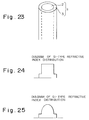
- a plastic optical fiber 1 as shown in a schematic perspective view of Fig. 23, which comprises a core 2 comprising a resin such as PMMA (polymethyl methacrylate resin), PC (polycarbonate resin), or a copolymer thereof; and a cladding 3 comprising a fluorine-containing resin, etc., and has a refractive index distribution (profile) as shown in Fig. 24, i.e., a step-index (SI) type optical fiber.
- a resin such as PMMA (polymethyl methacrylate resin), PC (polycarbonate resin), or a copolymer thereof
- a cladding 3 comprising a fluorine-containing resin, etc.
- a graded-index (GI) type optical fiber having a refractive index distribution as shown in Fig. 25.
- GI-type optical fiber is disclosed in Japanese Patent Publication (KOKOKU) Nos. 5857/1977 (Sho 52-5857) and 30301/1979 (Sho 54-30301), and Japanese Laid-open Patent Application (KOKAI) Nos. 130904/1986 (Sho 61-130904) and 162008/1986 (Sho 61-162008).
- KKOKU Japanese Patent Publication
- KOKKU Japanese Laid-open Patent Application
- these optical fibers still have various unsolved problems in view of the production thereof, etc., and an optical fiber having a desired property has not been obtained yet.
- the conventional plastic optical fibers since the refractive index distribution has been formed by utilizing a special chemical reaction such as one employing a difference in reactivity, and one employing a gel effect, there has been a severe limitation on the conditions such as the size of a preform, and the kind of a material, in view of the provision of a desired refractive index. Accordingly, the conventional plastic optical fibers have posed a problem such that mass production thereof is difficult or a fiber material having excellent transmission property and high reliability is difficult to be obtained.
- Japanese Laid-Open Patent Application No. 16504/1990 discloses a process for producing a plastic optical fiber by concentrically extruding a laminate product of two or more species of polymerizable mixtures for providing mutually different indices.
- Hei 2-16504 discloses a process for producing a plastic optical fiber by concentrically extruding a laminate product of two or more species of polymerizable mixtures for providing mutually different indices.
- the above process is a laminating-extrusion process and it can provide extrusion steps corresponding to only about ten layers, the resultant product is inevitably caused to have a stepped-type refractive index distribution.
- an optical fiber having such a stepped refractive index distribution it is difficult to transmit a large quantity of information.
- a continuous and smooth refractive index distribution can be provided by further diffusing a monomer into the product after the laminating-extrusion process.
- the above process includes an operation for conducting monomer diffusion the control of which is difficult, it is difficult to provide an ideal GI-type refractive index distribution.
- Japanese Laid-Open Patent Application No. 124602/1993 discloses a process for producing a plastic optical fiber by subjecting a core material to fiber spinning so as to provide a predetermined diameter, and coating the resultant product with a cladding material.
- a GI-type plastic optical fiber by such a coating operation using a cladding material, it is necessary to conduct multiple-stage coating operations, so that the production process becomes complicated.
- a GI-type preform (base material) is prepared in advance and is subjected to hot stretching to provide a fiber (Polymer Preprints, Japan, vol. 41, No. 7, pp. 2942-2944, Autumn of 1992). It is conceivable that such a process can reduce the number of production steps and can prepare various species of fibers having different outer diameters. However, according to the present inventors' investigation, in such a process wherein the GI-type preform is simply inserted into a drawing furnace to be subjected to fiber drawing, a fluctuation in the outer diameter after the fiber drawing is liable to occur and the strength of the resultant fiber thus obtained tends to become lower than that of fiber produced by other process.
- a cover portion called as a jacket layer or a sheath layer is further provided an the above-described cladding layer so as to protect the main body of the plastic optical fiber (as disclosed in Fig. 1 of Japanese Laid-Open Patent Application No. 230104/1985 (Sho 60-230104)).
- a fiber having a good heat resistance and a good weathering resistance can be provided by selecting a jacket or sheath material having a good heat resistance and a good weathering resistance.
- Japanese Laid-Open Patent Application No. 190204/1992 discloses a technique such that an inorganic filler is incorporated into a jacket layer so as to facilitate the formation of metal plating on the surface of the jacket layer.
- an optical fiber preform is drawn into a fiber shape and then a cover portion is formed on the resultant fiber by utilizing a method such as die coating and extrusion, and therefore the formation of the cover portion is troublesome and the productivity becomes low, whereby the resultant production cost becomes high.
- the main body of the optical fiber is caused to have a considerably large outer diameter so that the cladding layer may also function as a protecting layer.
- the amount of a plastic material to be used per unit length is increased.
- the plastic material to be used for a plastic optical fiber is one having a high optical transparency which has been produced so as to provide a high purity through purification, and has a high production cost, an increase in the amount of such as plastic material to be used per unit length constitutes a factor of an increase in the production cost.
- An object of the present invention is to provide a plastic optical fiber or a preform therefor, and a process and an apparatus for producing such a plastic optical fiber or a preform, which have solved the above-mentioned problems encountered in the Background Art.
- Another object of the present invention is to provide a process and an apparatus for producing a plastic optical fiber or a preform therefor, which has a desired refractive index distribution and is capable of being produced easily.
- a further object of the present invention is to provide a process and an apparatus for producing a plastic optical fiber or a preform therefor, which has a desired refractive index distribution and is capable of being produced at a low cost.
- a further object of the present invention is to provide a (drawing) process for producing a plastic optical fiber which can maintain a sufficient mechanical strength and can assure a long-term reliability after the fiber formation.
- a further object of the present invention is to provide a (drawing) process for producing a plastic optical fiber which can suppress a change in the outer diameter thereof due to heat and can assure a long-term reliability after the fiber formation.
- a further object of the present invention is to provide a process for producing a plastic optical fiber having a desired refractive index distribution and having a jacket layer which is capable of being easily formed.
- a further object of the present invention is to provide a process for producing a plastic optical fiber having a desired refractive index distribution and having a jacket layer which has been reduced in the production cost.
- a laminate or multi-layer structure which comprises a layer including a polymer and a material having a refractive index different from that or the polymer (hereinafter, referred to as "refractive index modifier") and in which the ratio of the polymer to the refractive index modifier is changed.
- the process for producing a plastic optical fiber preform according to the present invention is based on the above discovery. More specifically the present invention provides a process for producing a preform for plastic optical fiber having a refractive index distribution in which the refractive index is gradually decreased from the center of the preform toward the outer periphery thereof, by depositing a deposition layer comprising a polymer A (refractive index: N a ) and a refractive index modifier having a refractive index different from that of the polymer A onto an inner surface of a hollow cylindrical member rotating about an axis thereof, by use of vapor-phase deposition based on a CVD (Chemical Vapor Deposition) process, wherein the mixing ratio between the polymer A and the refractive index modifier constituting the deposition layer is changed thereby to gradually increase the refractive index of the deposition layer.
- CVD Chemical Vapor Deposition
- the refractive index modifier comprises a refractive index modifier B having a refractive index (N b ) higher than that of the polymer A , and the mixing ratio of the refractive index modifier B constituting the deposition layer is gradually increased.
- the refractive index modifier comprises a refractive index modifier C having a refractive index (N c ) lower than that of the polymer A , and the mixing ratio of the refractive index modifier C constituting the deposition layer is gradually decreased.
- the present invention also provides an apparatus for producing a preform for plastic optical fiber by forming a deposition layer comprising a polymer A (refractive index: N a ) and a refractive index modifier having a refractive index different from that of the polymer A on an inner surface of a hollow cylindrical member, by use of vapor-phase deposition based on a CVD process, the apparatus comprising: a rotating device for supporting the hollow cylindrical member so as to be rotatable about an axis thereof, a supply pipe located at one end portion of the hollow cylindrical member, for supplying vapor of a raw material for forming the deposition layer to the inner surface of the hollow cylindrical member, a heating device for heating the deposition layer deposited in the inside of the hollow cylindrical member, and raw material-supplying means for supplying the vapor of the raw material for forming the deposition layer to the supply pipe; wherein the raw material-supplying means includes refractive index-regulating means for changing the mixing ratio of the refractive index modifier in the vapor of the raw material.
- the present invention further provides a process for producing a preform for plastic optical fiber having a refractive index distribution in which the refractive index is gradually decreased from the center of the preform toward the outer periphery thereof, by depositing a deposition layer comprising a polymer A (refractive index: N a ) and a refractive index modifier having a refractive index different from that of the polymer A onto an inner surface of a hollow cylindrical member rotating about an axis thereof, by use of a coating process, wherein the mixing ratio between the polymer A and the refractive index modifier constituting the deposition layer is changed thereby to gradually increase the refractive index of the deposition layer.
- a deposition layer comprising a polymer A (refractive index: N a ) and a refractive index modifier having a refractive index different from that of the polymer A onto an inner surface of a hollow cylindrical member rotating about an axis thereof, by use of a coating process, wherein the mixing ratio between the polymer A and the
- the present invention further provides an apparatus for producing a preform for plastic optical fiber by forming a deposition layer comprising a polymer A (refractive index: N a ) and a refractive index modifier having a refractive index different from that of the polymer A on an inner surface of a hollow cylindrical member, by use of a coating process
- the apparatus comprising: a rotating device for supporting the hollow cylindrical member so as to be rotatable about an axis thereof, a supply pipe located at one end portion of the hollow cylindrical member, for supplying vapor of a raw material for forming the deposition layer to the inner surface of the hollow cylindrical member, a heating device for heating the deposition layer deposited in the inside of the hollow cylindrical member, and raw material-supplying means for supplying the raw material for forming the deposition layer to the supply pipe; wherein the raw material-supplying means includes refractive index-regulating means for changing the mixing ratio of the refractive index modifier in the raw material.
- an initial coating solution is prepared by using the polymer A (refractive index: N a ) and a refractive index modifier B having a refractive index (N b ) higher than that of the polymer A , and the mixing ratio of the refractive index modifier B in the coating solution is gradually increased.
- an initial coating solution is prepared by using the polymer A (refractive index: N a ) and a refractive index modifier C having a refractive index (N c ) lower than that of the polymer A , and the mixing ratio of the refractive index modifier C in the coating solution is gradually decreased.
- the present invention has an advantage such that a non-polymerizable material capable of imparting an excellent transmission property may be selected as the above-mentioned refractive index modifier.
- the present inventors have further found that in a process for drawing a GI-type preform into a fiber, the strength of the fiber is changed depending on the orientation of the polymer constituting the fiber, and have further found that it is very effective in solving the above problem in the fiber strength to appropriately adjust a drawing tension at the time of the drawing of the fiber.
- the present invention further provides a process for forming a plastic optical fiber by drawing while melting an optical fiber preform under heating; the optical fiber preform comprising, at least, a core comprising an organic polymer and a cladding layer comprising an organic polymer and disposed on the outer circumference of the core; wherein the drawing is conducted under a drawing tension of 10 g or more until winding-up of the optical fiber.
- the present invention further provides a process for forming a plastic optical fiber by drawing while melting an optical fiber preform under heating; the optical fiber preform comprising, at least, a core comprising an organic polymer and a cladding layer comprising an organic polymer and disposed on the outer circumference of the core; wherein the drawing is conducted under a drawing tension of 100 g or less until winding-up of the optical fiber.
- the present invention further provides a preform for plastic optical fiber, comprising: a core comprising an organic polymer, a cladding layer comprising an organic polymer and disposed on the outer circumference of the core, and a jacket layer disposed on the outer circumference of the cladding layer; wherein the jacket layer comprises a material which has the same quality as the material constituting the cladding layer, and has a purity lower than that of the material constituting the cladding layer.
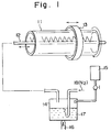
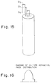
- Fig. 1 is a schematic perspective view showing an embodiment of the apparatus for producing an optical fiber preform by utilizing deposition based on an inside-surface CVD process in the present invention.
- Fig. 2 is a schematic perspective view showing an example of preform provided by the deposition shown in Fig. 1.
- Fig. 3 is a schematic view showing a refractive index distribution of the preform shown in Fig. 2.
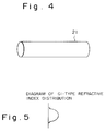
- Fig. 4 is a schematic perspective view showing a state of a preform which has been formed by the deposition and then collapsed.
- Fig. 5 is a schematic view showing a refractive index distribution at the state as shown in Fig. 4.
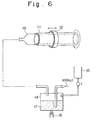
- Fig. 6 is a schematic perspective view showing another embodiment of the apparatus for producing an optical fiber preform by utilizing an inside-surface CVD process in the present invention.
- Fig. 7 is a schematic perspective view showing an embodiment of the apparatus for producing an optical fiber preform by utilizing deposition based on an inside-surface coating process in the present invention.
- Fig. 8 is a schematic perspective view showing another embodiment of the apparatus for producing an optical fiber preform by utilizing an inside-surface coating process in the present invention.
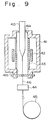
- Fig. 9 is a schematic sectional view showing an embodiment of the structure of a fiber drawing furnace for drawing an optical fiber preform in the process according to the present invention.
- Fig. 10 is a schematic perspective view showing an example of the structure of an optical fiber having a jacket layer.
- Fig. 11 is a schematic cross-sectional view showing an example of the structure of an optical fiber having a jacket layer.
- Fig. 12 is a schematic cross-sectional view showing an example of optical transmission in the optical fiber shown in Fig. 11.
- Fig. 13 is a schematic cross-sectional view showing an example of the structure of an optical fiber not having a jacket layer.
- Fig. 14 is a schematic cross-sectional view showing an example of optical transmission in the optical fiber shown in Fig. 13.
- Fig. 15 is a schematic perspective view showing a relationship among a cladding layer (layer thickness: D1), a core (diameter: D2), and a jacket layer (layer thickness: D3).
- Fig. 16 is a schematic view showing an embodiment of GI-type refractive index distribution of the optical fiber shown in Fig. 15.
- Fig. 17 is a schematic perspective view for illustrating a step (immersing step) in a case where an optical fiber preform having a jacket layer is prepared by a coating method using casting.
- Fig. 18 is a schematic perspective view far illustrating a step (pulling-up step) in a case where an optical fiber preform having a jacket layer is prepared by a coating method using casting.
- Fig. 19 is a schematic perspective view or illustrating a step (drying step) in a case where an optical fiber preform having a jacket layer is prepared by a coating method using casting.
- Fig. 20 is a schematic perspective view for illustrating a step (step of adding a refractive index modifier) in a case where an optical fiber preform having a jacket layer is prepared by a coating method using casting.
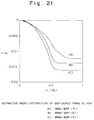
- Fig. 21 is a graph showing a refractive index distribution of each of the optical fibers obtained in Examples 3 and 6.
- Fig. 22 is a graph showing a relationship between fiber drawing tension and transmission loss in each of the optical fibers obtained in Examples 10-13 and Comparative Examples 5-7.
- Fig. 23 is a schematic perspective view showing an example of the structure of a conventional plastic optical fiber preform.
- Fig. 24 is a schematic view showing an SI-type refractive index distribution.
- Fig. 25 is a schematic view showing a GI-type refractive index distribution.
- the polymer A (refractive index: N a ) constituting a deposition layer to be deposited on an inside surface of a hollow cylindrical member rotating about an axis
- a known transparent polymer may be used without particular limitation.
- Specific example of such a polymer may include: homopolymers of methyl methacrylate (polymethyl methacrylate: PMMA), polycarbonate (PC); or a transparent copolymer of methyl methacrylate and another monomer.
- an “another monomer” may include: acrylic monomers such as monofunctional (meth)acrylates, fluorine-containing or fluorinated alkyl (meth)acrylates, polyfunctional (meth)acrylates, polyfunctional (meth)acrylates, acrylic acid, and methacrylic acid; and styrene-type monomers such as styrene and chlorostyrene.
- the material (refractive index modifier) having a refractive index different from that (N a ) of the above polymer A either of a refractive index modifier having a refractive index (N b ) higher than that of the polymer (refractive index modifier B), and a refractive index modifier having a refractive index (N c ) lower than that of the polymer (refractive index modifier C) may be used.
- the molecular weight of the refractive index modifier is not particularly restricted, as long as it may provide a desired refractive index distribution and may be stably copresent with the above-mentioned polymer.
- the refractive index modifier may be a monomer or a mixture thereof, or an oligomer or polymer.
- may preferably be 0.01 or more, more preferably 0.02 or more (particularly preferably, 0.03 or more).
- vinyl benzoate, benzyl methacrylate, and diallyl phthalate are refractive index modifiers having a polymerizable functional group.
- a multi-layer structure comprising a layer wherein the ratio of the above polymer A to the refractive index modifier is changed, on an inner surface of a hollow cylindrical member rotating about an axis
- either of a vapor deposition process and a coating process may be used.
- a chemical vapor deposition (CVD) process may preferably be used.
- Fig. 1 is a schematic perspective view showing an embodiment of the apparatus to be usable in the production of an optical fiber preform according to the present invention (an apparatus for producing an optical fiber preform according to the present invention).
- this apparatus is one for producing a plastic optical fiber preform by depositing vapor of a raw material in the inside of a hollow cylindrical member through a CVD process.
- This apparatus comprises: a rotating device (not shown) for supporting a hollow cylindrical member 11 so as to be rotatable around an axis thereof; a supply pipe 12 (in the form of a nozzle in Fig. 1) which is located at the axis center of the hollow cylindrical member, is reciprocatingly movable in the direction of the above axis, and comprises a plurality of spraying ports so as to spray the vapor of the raw material supplied thereto onto the inner surface of the hollow cylindrical member 11; a heating device 13 (in the form of a ring heater in Fig.
- the raw material-supplying means comprises a supply vessel 14 (in the form of a supply tank in Fig. 1) and a vessel 15 for a refractive index modifier (in the form of a refractive index modifier tank in Fig. 1) for supplying the refractive index modifier to the supply vessel 14.
- the raw material for a polymer to be supplied to the above nozzle 12 is stored as an organic raw material 17 in the supply tank 14 provided with a heating means 16 together with a solvent, and an inert gas 18 (such as N2, Ar and He) is introduced into the supply tank 14 so as to supply the vapor of the above material to the nozzle 12.
- an inert gas 18 such as N2, Ar and He
- a refractive index modifier B is stored in the refractive index modifier tank 15, and the refractive index modifier having a different refractive index is appropriately supplied to the supply tank 14 from the refractive index modifier tank 15 so as to control the resultant refractive index. More specifically, for example, as the deposition of a deposition layer comprising the above-mentioned polymer A and refractive index modifier B is repeated on the inner surface of the hollow cylindrical member 11, the refractive index modifier B is introduced into the supply tank 14 from the refractive index modifier tank 15, whereby the refractive index in the supply tank 14 is gradually changed to provide a predetermined gradient in the optical refractive index (refractive index distribution).
- a refractive index modifier C having a refractive index lower than that of the polymer A when a refractive index modifier C having a refractive index lower than that of the polymer A is used, for example, a predetermined mixture comprising the polymer A and the refractive index modifier C (a mixture having a refractive index lower than that of the polymer A per se) is placed in the supply tank 14, and the polymer A stored in the refractive index modifier tank 15 is gradually supplied to the supply tank 14 thereby to provide a desired refractive index distribution.
- the heating means 16 is not necessarily required. In other words, the heating means 16 may be omitted depending on the kind of the organic material to be used in combination with the apparatus.
- the polymer A has been poured into the supply tank 14 as an organic raw material solution 17 together with a solvent which is capable of dissolving the polymer A .
- the refractive index in the supply tank 14 is gradually changed by introducing the refractive index modifier B from the refractive index modifier tank 15 to the supply tank 14, whereby a predetermined gradient in the optical refractive index (refractive index distribution) is provided.
- the nozzle 12 is moved reciprocatingly in the direction of an axis while the hollow cylindrical member 11 is rotated, and the vapor of the raw material is sprayed onto the inner surface of the hollow cylindrical member 11 and heating is conducted by using the heating means 13, thereby to deposit the raw material having a gradually changing refractive index on the inner surface of the hollow cylindrical member 11.
- the heating means 13 thereby to deposit the raw material having a gradually changing refractive index on the inner surface of the hollow cylindrical member 11.
- a preform 20 having a cavity portion 20a extending in the direction of an axis, which corresponds to the nozzle 12 extending along the center axis.
- Fig. 3 schematically shows a profile of a refractive index distribution of the resultant preform before the collapse thereof.
- the preform 20 thus prepared is collapsed by melting under heating so as to fill up the above cavity 20a (Fig. 2), whereby a plastic optical fiber preform 21 as shown in a schematic perspective view of Fig. 4 is obtained.
- Fig. 5 is a graph schematically showing a refractive index distribution of the GI-type optical fiber preform thus obtained.
- a desired plastic optical fiber may be obtained by subjecting the optical fiber preform 21 thus obtained to an ordinary fiber drawing procedure.
- a plastic fiber may for example be obtained by drawing the above fiber preform 21 under melting due to heating, while the fiber preform 21 is kept vertically.
- a substance which is polymerizable under the action of energy such as light may be used as at least one of the raw material for the above polymer A (such as monomer) and the refractive index modifier B, and it may be subjected to polymerization (for example, photo-polymerization) under the application of energy ray such as ultraviolet ray, to fix the predetermined refractive index distribution as described above.
- energy ray such as ultraviolet ray
- an initiator for the photo-polymerization wherein cleavage may occur between different species of atoms due to light energy (the energy required for such cleavage may be smaller than that required for the cleavage of a single bond between atoms of the same kind).
- Specific examples of an initiator wherein cleavage may occur between different species of atoms due to light energy may include those as described below.
- benzoyl diphenylphosphine oxide benzoyl dimethylphosphine oxide benzoyl diethylphosphine oxide 2-methylbenzoyl diphenylphosphine oxide 2-methylbenzoyl dimethylphosphine oxide 2-methylbenzoyl diethylphosphine oxide 2,4-dimethylbenzoyl diphenylphosphine oxide 2,4-dimethylbenzoyl dimethylphosphine oxide 2,4-dimethylbenzoyl dimethylphosphine oxide 2,4-dimethylbenzoyl diethylphosphine oxide 2,4,6-trimethylbenzoyl diphenylphosphine oxide 2,4,6-trimethylbenzoyl dimethylphosphine oxide 2,4,6-trimethylbenzoyl diethylphosphine oxide 2,4,6-trimethylbenzoyl diethylphosphine oxide
- the hollow cylindrical member 11 by use of a material capable of transmitting ultraviolet light and to supply ultraviolet light from the outside of the hollow cylindrical member 11.
- a material capable of transmitting ultraviolet light and to supply ultraviolet light from the outside of the hollow cylindrical member 11.
- ultraviolet light is supplied from the outside of the hollow cylindrical member 11 is preferred in view of efficiency in the polymerization.
- Fig. 6 is a schematic perspective view showing another embodiment of an apparatus (for inside-surface CVD process) for producing an optical fiber preform according to the present invention.
- the embodiment shown in Fig. 6 has the same structure as that of the embodiment shown in Fig. 1, except that the nozzle 12 in Fig. 1 is omitted and a supply pipe 19 for introducing the vapor of a raw material is directly connected to an end portion of the rotating hollow cylindrical member 11 so as to directly supply the vapor of the raw material into the hollow cylindrical member 11.
- Fig. 7 is a schematic perspective view showing an embodiment of an apparatus usable for the production of an optical fiber preform according to the present invention (an apparatus to producing an optical fiber preform according to the present invention).
- this apparatus comprises: a rotating device (not shown) for supporting a hollow cylindrical member 31 so as to be rotatable about an axis thereof; a supply pipe (in the form of a spraying nozzle in Fig. 7) 32 which is located at the axis center of the above hollow cylindrical member 31 and is movable in the direction of the axis thereof so as to apply an organic material onto the inner surface of the hollow cylindrical member 31; a drying device (in the form of a ring heater in Fig. 7) 33 for heating the organic material deposited on the inside of the hollow cylindrical member 31 to remove a solvent contained therein; a supply tank 34 for supplying the organic material; and a tank 35 for a refractive index modifier.
- the polymer A has been poured as a spraying raw material into the supply tank 34 together with a solvent which is capable of dissolving the polymer A , while a refractive index modifier B is stored in the refractive index modifier tank 35.
- the refractive index modifier B is supplied from the refractive index modifier tank 35 to the supply tank 34 to gradually change the refractive index in the supply tank 34 so as to obtain a predetermined gradient in the optical refractive index (refractive index distribution).
- the nozzle 32 is moved reciprocatingly in the direction of the axis of the hollow cylindrical member 31, and a raw material (composition) comprising the polymer A and the refractive index modifier B is sprayed under drying based on a dryer 33.
- a raw material comprising the polymer A and the refractive index modifier B
- the spraying raw material having a gradually changing refractive index is sprayed thereby to form a core layer in which the retractive index is gradually decreased in the radial direction from the center or the preform toward the outer periphery thereof.
- a desired GI-type plastic optical fiber preform is provided by subjecting the resultant product to melting under heating so as to be collapsed.
- the optical fiber preform thus obtained is then subjected to an ordinary fiber drawing procedure, in the same manner as in the above embodiment using the CVD process.
- a plastic optical fiber may be obtained by subjecting the above optical fiber preform to melting under heating, while the preform is kept vertically.
- Fig. 8 shows another embodiment of the apparatus for producing an optical fiber preform (by a coating process) according to the present invention.
- the embodiment shown in Fig. 8 has the same structure as that of the embodiment shown in Fig. 7, except that, instead of the nozzle 32 movable in the direction of an axis as in Fig. 7, a nozzle 32a having a plurality of spraying ports 38 disposed along the direction of the axis of the hollow cylindrical member 31 is used, and a desired coating layer may be deposited onto an inner surface of the hollow cylindrical member 31 without moving the nozzle 32a in the axis direction.
- Fig. 9 is a schematic sectional view showing an apparatus for forming a plastic optical fiber by fiber drawing.
- a heater 42 and a core tube 43 are provided in the inside of the main body 41 of a fiber drawing furnace.
- a resin base material (preform) 40 for optical fiber is inserted into an upper opening 41a in the furnace main body 41, and melted under heating in the heating furnace 41, to be drawn or spun into a plastic optical fiber 46 having a predetermined outer diameter.
- the plastic optical fiber 46 thus drawn is pulled out through a lower opening 41b of the furnace 41, and then the plastic optical fiber 46 is wound up by use of a winding-up device 45 while the outer diameter of the resultant optical fiber 46 is measured by means of an outer diameter-measuring device (monitor) 44.
- one having a GI-type refractive index distribution in the core and cladding layer may preferably be used.
- a preform 40 which has been prepared by using a polymethyl methacrylate (PMMA) having excellent optical transparency for a cladding and using a compound having a higher refractive index for the core.
- PMMA polymethyl methacrylate
- the compound having a higher refractive index to be added to the core, and the outer diameter or the length of the preform are not particularly restricted.
- a drawing tension of 10 g or more to the preform (base material) 40 comprising a polymer during a period of time from the heating thereof based on the heating furnace 41 to the winding-up thereof by the winding-up device 45.
- the degree of orientation in a polymer is low, the molecules constituting the resultant polymer product assumes a randomly-oriented structure, and therefore the strength thereof is weak under stretching.
- the drawing tension is 10 g or more, the molecules are oriented along the longitudinal direction of the resultant fiber, whereby the tensile strength of the fiber may be improved and the long-term reliability thereof may be assured.
- the above drawing tension may preferably be 100 g or less.
- the drawing tension exceeds 100 g, the resultant fiber is liable to cause shrinkage under the action of heat.
- the reason for the occurrence of such a phenomenon may be considered as follows:
- the polymer constituting the cladding layer of an optical fiber is considerably oriented under the action of a drawing tension larger than 100 g, the fiber will be wound up around a reel, etc., in such a state that the cladding is so oriented.
- shrinkage occurs on the basis of the recovery of the polymer to its original state.
- the optical fiber per se is also shrunk and a strain is applied to the optical fiber in the longitudinal direction thereof to cause a structure defect of the fiber per se thereby to increase the transmission loss.
- the outer diameter of the optical fiber 46 may preferably be 1000 ⁇ m or less. In a case where the outer diameter exceeds 1000 ⁇ m, a decrease in the strength is not observed even when the degree of orientation of molecules is low. On the other hand, in a case where the outer diameter is 1000 ⁇ m or less, a decrease in the strength is considerable when the degree of orientation of molecules is low.
- the tensile strength of the fiber 46 is improved on the basis of the orientation of molecules along the longitudinal direction of the fiber thereby to assure long-term reliability, even when the outer diameter of optical fiber 46 is set to 1000 ⁇ m or less.
- the plastic optical fiber preform obtained by the production process according to the present invention as described above generally has a rod-like shape comprising a core and a cladding layer.
- a jacket layer is further formed as desired on the outer circumference of the rod comprising the core and the cladding layer, and the jacket layer comprises a material having substantially the same quality as that of an organic polymer constituting the cladding layer and having a lower purity than that of the organic polymer constituting the cladding layer.
- the material constituting the jacket layer may preferably be such a polymer B1 which has the same quality as that of the polymer B constituting the cladding layer and has a lower purity than that of the polymer B.
- the same quality means that the monomer constituting the material for the jacket layer is substantiallY common with the monomer constituting the polymer B for the cladding layer. More specifically, at least 90 mol% (more preferably, at least 95 mol%) of the monomer constituting the jacket layer is the same as the monomer constituting the polymer B for the cladding layer.
- the polymer B constituting the cladding layer has a high purity and contributes to light transmission, a polymer having a purity of at least 99 % may preferably be used as the polymer B constituting the cladding layer.
- a polymer having a purity of not more than 99 % may preferably be used in view of cost, etc.
- the polymer B1 may preferably have a purity of at least about 80 % (more preferably, at least about 90 %) in view of the adhesive property thereof with the cladding.
- this "purity" is used in a manner such that an impurity not contributing to light transmission at all (polymerization inhibitor, etc.) is excluded from the consideration of the purity. Accordingly, a component which contributes to light transmission (for example, a material to be added so as to change the refractive index) is not considered as an "impurity" relating to the evaluation of the above-mentioned purity.
- a material having a low purity for the jacket layer
- a material having a low cost for example, a commercially available and inexpensive polymer
- a plastic optical fiber having a low cost but having a good transmission property may be provided even when the outer diameter of the fiber is increased.
- the material constituting the jacket layer is one having the same quality as both of the core and the cladding, in consideration of the adhesion between the cladding and the core. More specifically, in such an embodiment, a material comprising at least 90 % (more preferably, at least 95 %) of the component (monomer, etc.) for the core material may preferably be used as the material constituting the jacket layer. On the other hand, in view of the production cost, a material comprising 99 % or less of the component (monomer, etc.) for the core material may preferably be used as the material constituting the jacket layer.
- the handling property at a working site, etc. may be improved and simultaneous peeling of the jacket layer may be effectively prevented in the peeling-off of a resin layer (an outermost layer 104 in Fig. 10 as described below).
- the material constituting the jacket layer may preferably have a melting point which is substantially equal to that of the core material. More specifically, when the melting point of the material for the jacket layer is denoted by m j and the melting point of the core material is denoted by m c ,
- (absolute value) may preferably be not more than 10 °C (i.e., the value of (m j - m c ) may preferably be within ⁇ 10 °C).
- the cladding layer and the jacket layer are liable to be melted nonuniformly (to be melted separately) at the time of the melting of the preform during a fiber drawing operation.
- Fig. 10 is a schematic perspective view showing an embodiment of the structure of an optical fiber which has been formed by forming a preform, coating the preform with a resin layer, and further subjecting the resultant preform to fiber drawing.
- the optical fiber in this embodiment comprises a core 101, a cladding layer 102 comprising a high-purity polymer and located on the outer circumference of the core 101, and a jacket layer 103 comprising a low-purity polymer and located on the outer circumference of the cladding layer 102.
- the jacket layer 102 is formed on the circumference of the cladding layer in the state of the preform in the above-mentioned manner, the jacket layer is simultaneously formed in the melt-drawing of the preform. Accordingly, in such an embodiment, it is not necessary to form the jacket layer by coating after the drawing, and therefore the resultant productivity is markedly improved.
- an outermost layer of resin layer 104 may be formed as desired on the circumference of the jacket layer 103, for the purpose of discrimination, etc.
- it is not necessarily required to impart a function as a protecting layer to the resin layer 104, and therefore a resin which is more inexpensive as compared with that in a conventional case can be used as the material for the resin layer 104.
- the resin layer 104 can be made thinner.
- the fiber when a connector is mounted to an optical fiber for the purpose of connection, it is necessary to remove the resin layer 104 from the plastic optical fiber.
- the fiber per se has the jacket layer 103 as in the plastic optical fiber produced according to the present invention, the fiber can maintain sufficient strength even after the removal of the resin layer 104 therefrom, and therefore such a fiber has an advantage that good strength may be maintained even in the connector portion.
- connecting means such as connectors are standardized in most cases.
- the main body outer diameter of which has been simply increased it is required that even the neighborhood of the outer periphery of the fiber not contributing to transmission is constituted by using a material having a high purity, for the purpose of meeting the standard, and therefore the resultant production cost is markedly increased.
- the production cost can be reduced by forming the jacket layer 103 having a low purity .
- the process according to the present invention is particularly suitable for a case in which the plastic optical fiber to be produced is a GI-type plastic optical fiber.
- the fiber is generally produced by pull down a liquefied core material due to melting in most cases.
- a preform having a refractive index distribution is first prepared and the preform is drawn into a fiber, as disclosed in Japanese Patent Publication No. 5857/1977 (Sho 52-5857). Accordingly, the present invention has an advantage that the production of the a preform with a jacket is facilitated by conducting a jacketting step in series at the time of the formation of the GI-type preform.
- an anti-oxidant such as hindered phenol, hindered amine, aryl amine, phosphite, and thio ether
- an anti-oxidant such as hindered phenol, hindered amine, aryl amine, phosphite, and thio ether
- a light absorbing agent 105 such as benzotriazole, benzophenone, benzoate, and cyanoacrylate
- stray light L x Fig. 14
- a light-scattering agent such as TiO2 powder may be incorporated into the jacket layer 103 so as to exhibit its light-scattering function.
- the thickness D1 of the cladding layer in the plastic optical fiber preform to be produced according to the present invention may preferably be not less than 10 % and not more than 40 % of the diameter D2 of the core.
- the thickness D3 of the jacket layer may preferably be greater than the thickness D1 of the cladding layer.
- D1 is less than 10 % of D2
- a part of light for communication also propagates in the jacket layer having a low transparency, so that the transmission performance can be lowered.
- Most of light for communication propagates in the core but a part of the light for communication spreads to the outside of the core so as to propagate in such a portion.
- the cladding may preferably has a thickness larger than that of the core to a certain extent.
- a GI-type refractive index distribution is formed so that the refractive index is gradually decreased from the center of the optical fiber preform toward the outer periphery thereof, as shown in Fig. 16.
- the process for producing such an optical fiber preform is not particularly restricted, but it is preferred to use an inside-surface CVD process or an inside-surface coating process (such as spray coating process) as described above may preferably be used.
- a drying operation may be conducted simultaneously with the coating operation, or the coating and drying operations may be conducted alternately.
- the optical fiber preform thus obtained may be subjected to an ordinary fiber drawing procedure (e.g., an operation wherein the optical fiber preform is melted under heating while the preform is vertically maintained), thereby to obtain a desired plastic optical fiber.
- an ordinary fiber drawing procedure e.g., an operation wherein the optical fiber preform is melted under heating while the preform is vertically maintained
- Figs. 17-20 schematically show an example of the coating process (cast coating process), which is different from spray coating or brush coating.
- reference numeral 51 denotes a starting rod
- numeral 52 denotes a coating tank
- numeral 53 denotes a dryer
- numeral 54 denotes a pipe for supplying a coating solution, respectively.
- the starting rod 51 is immersed in the coating tank 52 and then pulled up (Fig. 17 and Fig. 18), and thereafter the resultant product is subjected to drying by use of the dryer 53 (Fig. 19). Then, the above steps are treated or considered as one cycle, and while supplying a refractive index-adjusting raw material through the coating solution-supplying pipe 54 for every cycle so as to gradually or sequentially change the concentration of a refractive index-adjusting raw material in the coating tank 52, such a casting operation is repeated, thereby to form a cladding layer. Then, the raw material to be used is replaced with one having a lower purity, and a jacket layer is formed by using such a material.
- a preform for plastic optical fiber having a jacket layer and having a GI-type distribution as shown in Fig. 16 wherein the refractive index is gradually decreased from the center of the preform toward the outer periphery thereof.
- a transparent polymer A a transparent polymer A
- a hollow cylindrical member 11 comprising the polymer A as a main component was formed.
- the above polymer A (PMMA) was dissolved in a solvent (tetrahydrofuran: THF) in a predetermined ratio (concentration: about 30 wt.%) and the resultant solution was poured into a supply tank 14.
- THF tetrahydrofuran
- the hollow cylindrical member 11 obtained by the above-mentioned procedure was mounted to an unshown rotating device and the vapor of a raw material was uniformly supplied from the supply tank 14 onto the inner surface of the cylindrical member along the axis direction thereof, by use of a nozzle 12.
- the refractive index modifier B was gradually fed (flow rate: about 10 ml/min) from the refractive index modifier tank 15 into the supply tank 14, so that the mixing ratio of the refractive index modifier B was increased at every vapor-supplying operation to sequentially increase the refractive index of the deposition layer based on the vapor.
- a plastic optical fiber preform 21 (Fig. 4) having a GI-type refractive index distribution in which the refractive index was gradually decreased from the center of the preform toward the outer periphery thereof (as shown in Fig. 5).
- the mixture solution was dissolved in a solvent (tetrahydrofuran: THF) in a concentration of about 30 wt.%, and the resultant solution was poured into a supply tank 14.
- THF tetrahydrofuran
- a hollow cylindrical member 11 (refractive index: 1.410) was prepared by using a mixture solution having the same composition as that of the above solution, as a main component.
- the above polymer A was dissolved in THF (concentration: about 30 wt.%) to obtain a solution, and the resultant solution was stored in a refractive index modifier tank 15.
- the hollow cylindrical member 11 thus obtained was mounted to an unshown rotating device and the vapor of a raw material was directly supplied from the supply tank 14 onto the inner surface of the hollow cylindrical member 11 through a supply pipe 19 to be deposited thereon.
- the raw material A was gradually fed from the refractive index modifier tank 15 into the supply tank 14, so that the mixing ratio of the raw material A was increased at every deposition operation to gradually increase the refractive index of the deposition layer based on the vapor.
- a plastic optical fiber preform 21 (Fig. 4) having a GI-type refractive index distribution in which the refractive index was gradually decreased from the center of the preform toward the outer periphery thereof (as shown in Fig. 5).
- a laser diode (LD) having a wavelength of 0.658 ⁇ m was used as a light source for measurement of both the transmission loss and the band. Further, the band was measured by use of an FFT type optical oscilloscope (manufactured by Hamamatsu Photonics k.k.) while pulses with a half-value width of 60 psec were generated in the light source.
- Table 1 ⁇ Example 1 ⁇ ⁇ Example 2 ⁇ Transmission loss (dB/km) 100 120 Transmission band (MHz ⁇ km) 800 800
- a glass cylindrical member 11 having an inner diameter of 50 mm and an outer diameter of 52 mm was prepared, and a glass pipe having an inner diameter of 4 mm and an outer diameter of 5 mm was fixed at a position corresponding to the center of the cylindrical member.
- the glass pipe used herein had holes bored therein and having a diameter of 1 mm at intervals of 5 mm.
- MMA First methyl methacrylate
- an initiator benzil methyl ketal
- the vapor ejected from the glass pipe was attached to the inner surface of the above glass cylindrical member.
- the glass cylindrical member was rotated at a rotational speed of about one rotation per minute.
- a cladding layer (thickness: 5 mm) was formed on the basis of the polymerization of the above-mentioned methyl methacrylate.
- methyl methacrylate and an initiator were introduced into the glass pipe provided with the cladding layer formed above, and were subjected to polymerization under the same conditions as those for the formation of the above cladding layer, except for controlling the mixing ratio of a dopant (butyl benzyl phthalate ; BBP).
- a dopant butyl benzyl phthalate ; BBP.
- BBP butyl benzyl phthalate
- a solution of the dopant (concentration: about 30 wt.%) was placed in a dopant vessel 15, and was supplied at 10 ml/min from the vessel to the supply tank 14 in the formation of the above core.
- the resultant product was subjected to collapse under heating at 100 °C, thereby to obtain a base material (preform) having a refractive index distribution as shown in a graph of Fig. 21.
- the polymer A (PMMA) was dissolved in a solvent (tetrahydrofuran: THF) in a predetermined ratio (concentration: about 30 wt.%) and the resultant solution was poured into a supply tank 34.
- THF tetrahydrofuran
- the hollow cylindrical member 31 obtained by the above procedure was mounted to an unshown rotating device and the solution of raw material from the supply tank 14 was sprayed uniformly on the inner surface of the cylindrical member along the axis direction thereof, by use or a nozzle 32.
- the refractive index modifier B was gradually fed (flow rate: about 10 ml/min) from the refractive index modifier tank 35 into the supply tank 34, so that the mixing ratio of the refractive index modifier B was increased at every spraying operation to gradually increase the refractive index of the spraying solution.
- flow rate about 10 ml/min
- the mixing ratio of the refractive index modifier B was increased at every spraying operation to gradually increase the refractive index of the spraying solution.
- mixture solution was dissolved in a solvent (tetrahydrofuran: THF) in a concentration of about 30 wt.% and the resultant solution was poured into a supply tank 34.
- THF tetrahydrofuran
- a hollow cylindrical member (refractive index: 1.410) 31 was prepared by using a mixture solution having the same composition as that of the mixture solution described above, as a main component.
- the above polymer A was dissolved in THF (concentration: about 30 wt.%) to obtain a solution, and the resultant solution was stored in a refractive index modifier tank 35.
- the hollow cylindrical member 31 thus obtained was mounted to an unshown rotating device and the raw material from the supply tank 34 was sprayed uniformly onto the inside surface of the hollow cylindrical member 31 along the axis direction thereof, by use of the nozzle 32.
- the raw material A was gradually fed from the refractive index modifier tank 35 into the supply tank 34, so that the mixing ratio of the raw material A was increased at every spraying operation to gradually increase the refractive index of the spraying solution.
- this operation was repeated 100 times, there was obtained a plastic optical fiber preform 21 (Fig. 4) having a GI-type refractive index distribution in which the refractive index was gradually decreased from the center of the preform toward the outer periphery thereof (as shown in Fig. 5).
- a laser diode (LD) having a wavelength of 0.658 ⁇ m was used as a light source for measurement of both the transmission loss and the band. Further, the band was measured by use of an FFT type optical oscilloscope (manufactured by Hamamatsu Photonics k.k.) while pulses with a half-value width of 60 psec were generated in the light source.
- Table 2 ⁇ Example 4 ⁇ ⁇ Example 5 ⁇ Transmission loss (dB/km) 150 160 Transmission band (MHz ⁇ km) 700 800
- a glass cylindrical member 31 having an inner diameter of 50 mm and an outer diameter of 52 mm was prepared, and a glass pipe 32a having an inner diameter of 4 mm and an outer diameter of 5 mm was fixed at a position corresponding to the center of the cylindrical member.
- the glass pipe used herein had holes bored therein and having a diameter of 1 mm at intervals of 5 mm.
- a THF solution (concentration: about 30 wt.%) of polymethyl methacrylate (PMMA) was placed in a supply tank 34, and the solution was supplied into the glass pipe 32a (flow rate: about 10 ml/min). The solution was uniformly sprayed from the pipe 32a onto the inside surface of the glass cylindrical member 31 along the axis direction thereof. The glass cylindrical member was rotated at a rotational speed of about one rotation per minute.
- PMMA polymethyl methacrylate
- a cladding layer (thickness: 5 mm) was formed on the basis of the spraying of the above solution of polymer A .
- the above methyl methacrylate solution was introduced into the glass pipe 31 provided with the cladding layer formed above, and was subjected to spraying under the same conditions as those for the formation of the above cladding layer, except for controlling the mixing ratio of a dopant (butyl benzyl phthalate ; BBP).
- a dopant butyl benzyl phthalate ; BBP
- BBP butyl benzyl phthalate
- a solution of the dopant (concentration: about 30 wt.%) was placed in a dopant vessel 35, and was supplied at about 10 ml/min from the vessel to the supply tank 34 in the formation of the above core.
- the resultant product was subjected to collapse under heating at 100 °C, thereby to obtain a preform.
- Each of these preforms had a refractive index distribution which was substantially comparable to that shown in the above-mentioned graph of Fig. 21.
- a plastic optical fiber preform 40 provided with a GI-type refractive index distribution was subjected to a fiber drawing operation.
- the above preform 40 was inserted into a fiber drawing furnace 41 in which the temperature in the core tube was set to 240 °C, and was subjected to fiber drawing at a linear velocity of 2 m/min so as to provide a center value of the resultant outer diameter of 650 ⁇ m.
- the drawing tension used herein was 20 g.
- the tensile strength of the thus prepared fiber 46 was measured, it was found to be 2.3 Kg/mm2.
- a length of 1 m of the fiber was wound up with a tension of 50 g around a mandrel having a diameter of 10 mm, the period of time until the breakage thereof was 10 days.
- a plastic optical fiber preform 40 provided with a GI-type refractive index distribution was provided and was inserted into a fiber drawing furnace 41 in which the temperature in the core tube was set to 230 °C, and was subjected to fiber drawing at a linear velocity of 2 m/min so as to provide a center value of the resultant outer diameter of 650 ⁇ m.
- the drawing tension used herein was 40 g.
- the tensile strength of the thus prepared fiber 46 was measured, it was found to be 2.4 Kg/mm2.
- a length of 1 m of the fiber was wound up with a tension of 50 g around a mandrel having a diameter of 10 mm, the period of time until the breakage thereof was 12 days.
- a plastic optical fiber preform 40 provided with a GI-type refractive index distribution was provided and was inserted into a fiber drawing furnace 41 in which the temperature in the core tube was set to 250 °C, and was subjected to fiber drawing at a linear velocity of 2 m/min so as to provide a center value of the resultant outer diameter of 650 ⁇ m.
- the drawing tension used herein was 15 g.
- the tensile strength of the thus prepared fiber 46 was measured, it was found to be 2.3 Kg/mm2.
- a length of 1 m of the fiber was wound up with a tension of 50 g around a mandrel having a diameter of 10 mm, the period of time until the breakage thereof was 8 days.
- a plastic optical fiber preform 40 provided with a GI-type refractive index distribution was provided and was inserted into a fiber drawing furnace 41 in which the temperature in the core tube was set to 260 °C, and was subjected to fiber drawing at a linear velocity of 2 m/min so as to provide a center value of the resultant outer diameter of 650 ⁇ m.
- the drawing tension used herein was 8 g.
- the tensile strength of the thus prepared fiber 46 was measured, it was found to be 1.5 Kg/mm2.
- a length of 1 m of the fiber was wound up with a tension of 50 g around a mandrel having a diameter of 10 mm, the period of time until the breakage thereof was 10 hours.
- a plastic optical fiber preform 40 provided with a GI-type refractive index distribution was provided and was inserted into a fiber drawing furnace 41 in which the temperature in the core tube was set to 260 °C, and was subjected to fiber drawing at a linear velocity of 1.5 m/min so as to provide a center value of the resultant outer diameter of 650 ⁇ m.
- the drawing tension used herein was 6 g.
- the tensile strength of the thus prepared fiber 46 was measured, it was found to be 1.3 Kg/mm2.
- the period of time until the breakage thereof was 8 hours.
- a plastic optical fiber preform 40 provided with a GI-type refractive index distribution was provided and was inserted into a fiber drawing furnace 41 in which the temperature in the core tube was set to 270 °C, and was subjected to fiber drawing at a linear velocity of 2 m/min so as to provide a center value of the resultant outer diameter of 650 ⁇ m.
- the drawing tension used herein was 5 g.
- the tensile strength of the thus prepared fiber 46 was measured, it was found to be 1.0 Kg/mm2.
- the period of time until the breakage thereof was 3 hours.
- a plastic optical fiber preform 40 provided with a GI-type refractive index distribution was provided and was inserted into a fiber drawing furnace 41 in which the temperature in the core tube was set to 275 °C, and was subjected to fiber drawing at a linear velocity of 2 m/min so as to provide a center value of the resultant outer diameter of 1100 ⁇ m.
- the drawing tension used herein was 5 g.
- the tensile strength of the thus prepared fiber 46 was measured, it was found to be 2.2 Kg/mm2.
- a length of 1 m of the fiber was wound up with a tension of 50 g around a mandrel having a diameter of 10 mm, the period of time until the breakage thereof was 10 days, and substantially no decrease in the strength was observed.
- a preform for plastic optical fiber 40 having a GI-type refractive index distribution was provided and was inserted into a fiber drawing furnace 41 in which the heater 42 comprised a carbon heater having a length of heating zone of 10 mm and the temperature in the core tube was set at 220 °C.
- the above fiber was subjected to a deterioration treatment at 80 °C for one day (24 hours), and then the shrinkage retention (retention in shrinkage) and transmission loss thereof were measured. As a result, they were found to be 99% and 210 dB/km, respectively. In other words, substantially no shrinkage due to heat was observed, and the fluctuation in the transmission loss was little.
- the results of the measurement of the transmission loss are shown in a graph of Fig. 22.
- a preform for plastic optical fiber 40 having a GI-type refractive index distribution was provided and was inserted into a fiber drawing furnace 41 in which the heater 42 comprised a carbon heater having a length of heating zone of 10 mm and the temperature in the core tube was set at 220 °C.
- the above fiber was subjected to a deterioration treatment at 80 °C for one day, and then the shrinkage retention and transmission loss thereof were measured. As a result, they were found to be 99% and 190 dB/km, respectively. In other words, substantially no shrinkage due to heat was observed, and the fluctuation in the transmission loss was little.
- the results of the measurement of the transmission loss are shown in a graph of Fig. 22.
- a preform for plastic optical fiber 40 having a GI-type refractive index distribution was provided and was inserted into a fiber drawing furnace 41 in which the heater 42 comprised a carbon heater having a length of heating zone of 10 mm and the temperature in the core tube was set at 230 °C.
- the above fiber was subjected to a deterioration treatment at 80 °C for one day, and then the shrinkage retention and transmission loss thereof were measured. As a result, they were found to be 98% and 210 dB/km, respectively. In other words, substantially no shrinkage due to heat was observed, and the fluctuation in the transmission loss was little.
- the results of the measurement of the transmission loss are shown in a graph of Fig. 22.
- a preform for plastic optical fiber 40 having a GI-type refractive index distribution was provided and was inserted into a fiber drawing furnace 41 in which the heater 42 comprised a heater comprising carbon resistance(carbon heater) having a length of heating zone of 10 mm and the temperature in the core tube was set at 210 °C.
- the above fiber was subjected to a deterioration treatment at 80 °C for one day, and then the shrinkage retention and transmission loss thereof were measured. As a result, they were found to be 97% and 230 dB/km, respectively. In other words, substantially no shrinkage due to heat was observed, and the fluctuation in the transmission loss was little.
- the results of the measurement of the transmission loss are shown in a graph of Fig. 22.
- a preform for plastic optical fiber 40 having a GI-type refractive index distribution was provided and was inserted into a fiber drawing furnace 41 in which the temperature in the core tube was set to 200 °C.
- the above fiber was subjected to a deterioration treatment at 80 °C for one day, and then the shrinkage retention and transmission loss thereof were measured. As a result, they were found to be 90% and 300 dB/km, respectively. In other words, a somewhat larger shrinkage due to heat was observed, and the fluctuation in the transmission loss was also large.
- the results of the measurement of the transmission loss are shown in a graph of Fig. 22.
- a preform for plastic optical fiber 40 having a GI-type refractive index distribution was provided and was inserted into a fiber drawing furnace 41 in which the temperature in the core tube was set to 200 °C.
- the above fiber was subjected to a deterioration treatment at 80 °C for one day, and then the shrinkage retention and transmission loss thereof were measured. As a result, they were found to be 90% and 350 dB/km, respectively. In other words, a somewhat larger shrinkage due to heat was observed, and the fluctuation in the transmission loss was also large.
- the results of the measurement of the transmission loss are shown in a graph of Fig. 22.
- a preform for plastic optical fiber 40 having a GI-type refractive index distribution was provided and was inserted into a fiber drawing furnace 41 in which the temperature in the core tube was set to 220 °C.
- the above fiber was subjected to a deterioration treatment at 80 °C for one day, and then the shrinkage retention and transmission loss thereof were measured. As a result, they were found to be 80% and 400 dB/km, respectively. In other words, a somewhat larger shrinkage due to heat was observed, and the fluctuation in the transmission loss was also large.
- the results of the measurement of the transmission loss are shown in a graph of Fig. 22.
- the tension for drawing is set to a value of 10 g or more at the time of the production of a plastic optical fiber based on drawing (particularly, when the outer diameter of the resultant fiber is 1000 ⁇ m or less), it is possible to further improve the resultant fiber in mechanical strength and long-term reliability.
- the tension for drawing is set to a value of 100 g or less at the time of the production of a plastic optical fiber based on drawing, the shrinkage of the resultant fiber can be suppressed and the increase in the transmission loss can be suppressed even after the heat deterioration thereof.
- the following effects may be achieved even in the case of a plastic optical fiber preform having a jacket layer.
Landscapes
- Physics & Mathematics (AREA)
- General Physics & Mathematics (AREA)
- Optics & Photonics (AREA)
- Engineering & Computer Science (AREA)
- Mechanical Engineering (AREA)
- Health & Medical Sciences (AREA)
- Manufacturing & Machinery (AREA)
- Ophthalmology & Optometry (AREA)
- Optical Fibers, Optical Fiber Cores, And Optical Fiber Bundles (AREA)
Applications Claiming Priority (11)
| Application Number | Priority Date | Filing Date | Title |
|---|---|---|---|
| JP5144678A JPH075330A (ja) | 1993-06-16 | 1993-06-16 | プラスチック光ファイバ母材の製造方法及び装置 |
| JP144678/93 | 1993-06-16 | ||
| JP5147278A JPH075332A (ja) | 1993-06-18 | 1993-06-18 | プラスチック光ファイバ母材及びその製造方法 |
| JP147278/93 | 1993-06-18 | ||
| JP5151776A JPH0713030A (ja) | 1993-06-23 | 1993-06-23 | プラスチック光ファイバ母材の製造方法及び装置 |
| JP151776/93 | 1993-06-23 | ||
| JP24137/94 | 1994-02-22 | ||
| JP6024137A JPH07234322A (ja) | 1994-02-22 | 1994-02-22 | プラスチック光ファイバの線引方法 |
| JP27743/94 | 1994-02-25 | ||
| JP6027743A JPH07234324A (ja) | 1994-02-25 | 1994-02-25 | プラスチック光ファイバの線引方法 |
| PCT/JP1994/000963 WO1994029758A1 (en) | 1993-06-16 | 1994-06-14 | Plastic optical fiber base material, production method therefor, and apparatus therefor |
Publications (2)
| Publication Number | Publication Date |
|---|---|
| EP0664463A1 true EP0664463A1 (de) | 1995-07-26 |
| EP0664463A4 EP0664463A4 (de) | 1997-08-20 |
Family
ID=27520607
Family Applications (1)
| Application Number | Title | Priority Date | Filing Date |
|---|---|---|---|
| EP94917812A Withdrawn EP0664463A4 (de) | 1993-06-16 | 1994-06-14 | Grundmaterial für optische fasern aus kunststoff, sowie verfahren und vorrichtung zu dessen herstellung. |
Country Status (3)
| Country | Link |
|---|---|
| US (2) | US5614253A (de) |
| EP (1) | EP0664463A4 (de) |
| WO (1) | WO1994029758A1 (de) |
Cited By (2)
| Publication number | Priority date | Publication date | Assignee | Title |
|---|---|---|---|---|
| US6028178A (en) * | 1994-10-05 | 2000-02-22 | Clariant Gmbh | Pigment for electrophotographic toners and developers |
| US6049378A (en) * | 1997-08-05 | 2000-04-11 | Pruftechnik Dieter Busch Ag | Device and method for mutually aligning bodies |
Families Citing this family (27)
| Publication number | Priority date | Publication date | Assignee | Title |
|---|---|---|---|---|
| EP0664463A4 (de) * | 1993-06-16 | 1997-08-20 | Sumitomo Electric Industries | Grundmaterial für optische fasern aus kunststoff, sowie verfahren und vorrichtung zu dessen herstellung. |
| JPH10253839A (ja) * | 1997-03-07 | 1998-09-25 | Sumitomo Wiring Syst Ltd | 屈折率分布型プラスチック光ファイバの製造方法および製造装置 |
| JPH10253840A (ja) * | 1997-03-07 | 1998-09-25 | Sumitomo Wiring Syst Ltd | 屈折率分布型プラスチック光ファイバの製造方法および製造装置 |
| JPH10260322A (ja) * | 1997-03-17 | 1998-09-29 | Sumitomo Wiring Syst Ltd | 屈折率分布型プラスチック光ファイバの製造方法および製造装置 |
| US6086999A (en) * | 1997-06-12 | 2000-07-11 | Boston Optical Fiber, Inc. | Method for producing a graded index plastic optical material |
| JPH1184145A (ja) * | 1997-09-11 | 1999-03-26 | Sumitomo Wiring Syst Ltd | プラスチック光ファイバの線引装置における加熱炉 |
| JPH11119035A (ja) * | 1997-10-14 | 1999-04-30 | Sumitomo Wiring Syst Ltd | 屈折率分布型プラスチック光ファイバ用プリフォームの製造方法 |
| DK1059544T3 (da) * | 1998-02-24 | 2003-09-29 | Mitsubishi Rayon Co | Optisk fiber af plast, optisk fiberkabel, optisk fiberkabel med stik, fremgangsmåde til fremstilling af methylmethacrylatbaseret polymer og fremgangsmåde til fremstilling af optisk fiber af plast |
| US6776932B1 (en) | 1998-06-12 | 2004-08-17 | Getronics Wang Co. Llc | Polymeric optical articles |
| US6254808B1 (en) | 1999-05-27 | 2001-07-03 | Lucent Technologies Inc. | Process for fabricating plastic optical fiber |
| US6265018B1 (en) * | 1999-08-31 | 2001-07-24 | Lucent Technologies Inc. | Fabricating graded index plastic optical fibers |
| KR100368692B1 (ko) * | 2000-03-21 | 2003-01-24 | 옵티미디아(주) | 반경 방향으로 변화하는 물성을 지니는 봉형 고분자 모재,그의 제조방법 및 이에 사용되는 장치 |
| US6527986B2 (en) | 2001-02-07 | 2003-03-04 | Fitel Usa Corp. | Extrusion process for fabricating plastic optical fiber |
| WO2003029156A1 (de) * | 2001-09-28 | 2003-04-10 | Schott Glas | Verfahren und vorrichtung zur formung eines strukturierten körpers sowie verfahrensgemäss hergestellter körper |
| EP1472073A1 (de) * | 2001-12-31 | 2004-11-03 | General Components Inc. | Lichtwellenleiterherstellungssystem und querspritzkopfdüse dafür |
| US20030132536A1 (en) * | 2001-12-31 | 2003-07-17 | General Components, Inc. | Method of making a graded index polymer optical fiber |
| US20030190130A1 (en) * | 2002-04-05 | 2003-10-09 | Paradigm Optics, Inc. | Multiple optical pathway fiber optic cable |
| KR100460720B1 (ko) * | 2002-05-22 | 2004-12-08 | 에스에스씨피 주식회사 | 플라스틱 광섬유 모재 및 이의 제조방법 |
| US6861148B2 (en) * | 2002-11-22 | 2005-03-01 | Chromis Fiberoptics, Llc | Plastic optical fiber preform |
| US20050157999A1 (en) * | 2002-12-27 | 2005-07-21 | Zhen Zhen | Graded index polymer optical fiber and a method of making the same |
| KR20040064314A (ko) * | 2003-01-10 | 2004-07-19 | 주식회사 코오롱 | 자외선 안정성이 우수한 플라스틱 광섬유 및 그의 제조방법 |
| CN1771443A (zh) * | 2003-02-10 | 2006-05-10 | 纳诺博蒂克斯公司 | 制造塑料光传输介质的方法和装置 |
| US7708688B2 (en) * | 2004-03-15 | 2010-05-04 | Paradigm Optics, Incorporated | Polymer endoscopic shaft |
| TW200848561A (en) * | 2006-12-22 | 2008-12-16 | Body Organ Biomedical Corp | Device for manufacturing fibrils |
| DE102013009169B4 (de) | 2013-05-28 | 2016-05-12 | Freundes- und Förderkreis des Institutes für Textiltechnik der RWTH Aachen e.V. | Verfahren zum Schmelzspinnen einer über ihren Querschnitt variierenden Faser sowie ihre Verwendung |
| US11009662B2 (en) * | 2017-09-05 | 2021-05-18 | Facebook Technologies, Llc | Manufacturing a graded index profile for waveguide display applications |
| JP2022510751A (ja) | 2018-08-31 | 2022-01-28 | ザ・ユニバーシティ・オブ・シドニー | ファイバ形成方法 |
Family Cites Families (32)
| Publication number | Priority date | Publication date | Assignee | Title |
|---|---|---|---|---|
| JPS525857A (en) * | 1975-07-01 | 1977-01-17 | Nippon Zeon Co Ltd | Cross-linkable halogen-containing polymecomposition |
| US4529427A (en) * | 1977-05-19 | 1985-07-16 | At&T Bell Laboratories | Method for making low-loss optical waveguides on an industrial scale |
| JPS545743A (en) * | 1977-06-16 | 1979-01-17 | Oki Electric Ind Co Ltd | Production of photo self-convergent type element |
| JPS5430301A (en) * | 1977-08-10 | 1979-03-06 | Hitachi Ltd | Drum level reduction preventive device of natural circulation boiler |
| US4334903A (en) * | 1977-08-29 | 1982-06-15 | Bell Telephone Laboratories, Incorporated | Optical fiber fabrication |
| JPS5666807A (en) * | 1979-11-05 | 1981-06-05 | Ricoh Co Ltd | Production of focusing type optical transmission body |
| JPS58178302A (ja) * | 1982-04-12 | 1983-10-19 | Sumitomo Electric Ind Ltd | 耐熱性プラスチツク光フアイバ− |
| JPS599603A (ja) * | 1982-07-09 | 1984-01-19 | Mitsubishi Rayon Co Ltd | アクリル系プラスチツク光フアイバ−ケ−ブル、および、その製造方法 |
| US4568146A (en) * | 1982-10-21 | 1986-02-04 | Sumitomo Electric Industries, Ltd. | Plastic optical fiber and production thereof |
| US4692347A (en) * | 1983-07-07 | 1987-09-08 | The Curators Of The University Of Missouri | Method of interiorly coating tubing |
| JPS6057811A (ja) * | 1983-09-09 | 1985-04-03 | Nippon Telegr & Teleph Corp <Ntt> | プラステイツク光フアイバコ−ドの製造方法 |
| JPS60119510A (ja) * | 1983-12-02 | 1985-06-27 | Sumitomo Electric Ind Ltd | プラスチツク光フアイバ−用プリフオ−ムの製造方法 |
| JPS60119509A (ja) * | 1983-12-02 | 1985-06-27 | Sumitomo Electric Ind Ltd | プラスチツク光フアイバ−用プリフオ−ムの製造方法 |
| JPS60230104A (ja) * | 1984-04-27 | 1985-11-15 | Dainichi Nippon Cables Ltd | 光フアイバ |
| JPS616604A (ja) * | 1984-06-21 | 1986-01-13 | Mitsubishi Rayon Co Ltd | プラスチツク系光伝送性繊維 |
| JPS61130904A (ja) * | 1984-11-30 | 1986-06-18 | Nippon Sheet Glass Co Ltd | 合成樹脂光伝送体を製造する方法 |
| JPS61162008A (ja) * | 1985-01-12 | 1986-07-22 | Fujitsu Ltd | プラスチツク光フアイバの製造方法 |
| NO853303L (no) * | 1985-08-22 | 1987-02-23 | Norsk Hydro As | Preform med gradert brytningsindeks og fremgangsmaate for fremstilling av samme. |
| JPS62172307A (ja) * | 1986-01-27 | 1987-07-29 | Mitsubishi Rayon Co Ltd | プラスチツク光伝送性繊維 |
| JPH06100690B2 (ja) * | 1986-09-01 | 1994-12-12 | 株式会社日立製作所 | 合成樹脂製光伝送体の製造方法 |
| US4900623A (en) * | 1986-10-10 | 1990-02-13 | Hoechst Celanese Corporation | Ultrathin polymethylmethacrylate polymer films |
| US4830461A (en) * | 1987-01-29 | 1989-05-16 | Bridgestone Corporation | Pressure-sensitive sensors |
| CA1335022C (en) * | 1987-07-30 | 1995-03-28 | Tsuruyoshi Matsumoto | Cladding material for optical fiber |
| JP2860382B2 (ja) * | 1988-07-05 | 1999-02-24 | 三菱レイヨン株式会社 | プラスチック光伝送体の製造法 |
| FR2657556B1 (fr) * | 1990-01-26 | 1994-07-01 | Bosc Dominique | Procede de fabrication de guides optiques circulaires monomodes en polymere. |
| JP3010369B2 (ja) * | 1990-08-16 | 2000-02-21 | 康博 小池 | 合成樹脂光伝送体を製造する方法 |
| FR2666046B1 (fr) * | 1990-08-24 | 1994-07-08 | France Telecom | Procede de fabrication de composants electrooptiques dans des guides d'onde optique cylindriques monomodes en polymere. |
| JPH04124602A (ja) * | 1990-09-14 | 1992-04-24 | Furukawa Electric Co Ltd:The | プラスチック光ファイバの製造方法 |
| JPH04190204A (ja) * | 1990-11-24 | 1992-07-08 | Hitachi Ltd | プラスチック光ファイバおよびその製法 |
| JPH04248506A (ja) * | 1991-02-04 | 1992-09-04 | Mitsubishi Rayon Co Ltd | 光ファイバコード |
| JPH063533A (ja) * | 1992-06-18 | 1994-01-14 | Mitsubishi Rayon Co Ltd | 屈折率分布型プラスチック光伝送体の製法 |
| EP0664463A4 (de) * | 1993-06-16 | 1997-08-20 | Sumitomo Electric Industries | Grundmaterial für optische fasern aus kunststoff, sowie verfahren und vorrichtung zu dessen herstellung. |
-
1994
- 1994-06-14 EP EP94917812A patent/EP0664463A4/de not_active Withdrawn
- 1994-06-14 WO PCT/JP1994/000963 patent/WO1994029758A1/ja not_active Ceased
- 1994-06-14 US US08/381,875 patent/US5614253A/en not_active Expired - Fee Related
-
1997
- 1997-01-02 US US08/775,881 patent/US5851666A/en not_active Expired - Fee Related
Cited By (3)
| Publication number | Priority date | Publication date | Assignee | Title |
|---|---|---|---|---|
| US6028178A (en) * | 1994-10-05 | 2000-02-22 | Clariant Gmbh | Pigment for electrophotographic toners and developers |
| US6168895B1 (en) | 1994-10-05 | 2001-01-02 | Clariant Gmbh | Pigment for electrophotographic toners and developers |
| US6049378A (en) * | 1997-08-05 | 2000-04-11 | Pruftechnik Dieter Busch Ag | Device and method for mutually aligning bodies |
Also Published As
| Publication number | Publication date |
|---|---|
| WO1994029758A1 (en) | 1994-12-22 |
| US5614253A (en) | 1997-03-25 |
| EP0664463A4 (de) | 1997-08-20 |
| US5851666A (en) | 1998-12-22 |
Similar Documents
| Publication | Publication Date | Title |
|---|---|---|
| US5891570A (en) | Plastic optical fiber preform having a jacket layer | |
| EP0664463A1 (de) | Grundmaterial für optische fasern aus kunststoff, sowie verfahren und vorrichtung zu dessen herstellung | |
| EP0615141B1 (de) | Verfahren zur Herstellung von Kunststofflichtleitern | |
| JPWO1994004949A1 (ja) | プラスチック光伝送体の製造方法 | |
| EP0472384A2 (de) | Optische Faser und Verfahren zu ihrer Herstellung | |
| CN1938618A (zh) | 塑料光纤及其制造方法 | |
| EP0662620A1 (de) | Verfahren und vorrichtung zur herstellung eines basismaterials für optischen fasern | |
| EP1509380B1 (de) | Optisches kunststoffprodukt, optische kunststofffaser, vorrichtung zur herstellung eines optischen kunststoffteils und verfahren zur herstellung eines optischen kunststoffteils und eines optischen kunststoffprodukts | |
| JPH0727928A (ja) | プラスチック光伝送体の製造方法 | |
| JPH0713029A (ja) | プラスチック光ファイバ母材の製造方法及び装置 | |
| Duan et al. | Fabrication of segmented cladding fiber by bicomponent spinning | |
| JPH08227019A (ja) | プラスチック光ファイバ母材の製造方法 | |
| JPH08313734A (ja) | プラスチック光ファイバの製造方法 | |
| JPH08146259A (ja) | プラスチック光ファイバコードの製造方法 | |
| JPH09138313A (ja) | 屈折率分布型プラスチック光ファイバの製造方法 | |
| JP3444317B2 (ja) | プラスチック光ファイバ | |
| JPH075332A (ja) | プラスチック光ファイバ母材及びその製造方法 | |
| JP4231282B2 (ja) | プラスチック光学部材の製造方法とプラスチック光ファイバ | |
| JPH0713030A (ja) | プラスチック光ファイバ母材の製造方法及び装置 | |
| KR20050071713A (ko) | 플라스틱 광학 부품 생산용 예비성형품, 이 예비성형품의제조방법 및 플라스틱 광학 섬유 | |
| Harlin et al. | Manufacturing methods for multi step index plastic optical fiber materials | |
| JPH075331A (ja) | プラスチック光ファイバ母材の製造方法 | |
| JPH08146233A (ja) | プラスチック光ファイバの線引方法 | |
| JPH0713028A (ja) | プラスチック光ファイバ母材の製造方法及び装置 | |
| JP2006506502A (ja) | 光学部材、その製造のための組成物 |
Legal Events
| Date | Code | Title | Description |
|---|---|---|---|
| PUAI | Public reference made under article 153(3) epc to a published international application that has entered the european phase |
Free format text: ORIGINAL CODE: 0009012 |
|
| 17P | Request for examination filed |
Effective date: 19950327 |
|
| AK | Designated contracting states |
Kind code of ref document: A1 Designated state(s): DE FR GB IT NL |
|
| A4 | Supplementary search report drawn up and despatched | ||
| AK | Designated contracting states |
Kind code of ref document: A4 Designated state(s): DE FR GB IT NL |
|
| 17Q | First examination report despatched |
Effective date: 20020318 |
|
| STAA | Information on the status of an ep patent application or granted ep patent |
Free format text: STATUS: THE APPLICATION IS DEEMED TO BE WITHDRAWN |
|
| 18D | Application deemed to be withdrawn |
Effective date: 20020729 |