EP0661663A2 - Druckvorrichtung und -verfahren die über eine Tonersparfunktion verfügen - Google Patents
Druckvorrichtung und -verfahren die über eine Tonersparfunktion verfügen Download PDFInfo
- Publication number
- EP0661663A2 EP0661663A2 EP94120316A EP94120316A EP0661663A2 EP 0661663 A2 EP0661663 A2 EP 0661663A2 EP 94120316 A EP94120316 A EP 94120316A EP 94120316 A EP94120316 A EP 94120316A EP 0661663 A2 EP0661663 A2 EP 0661663A2
- Authority
- EP
- European Patent Office
- Prior art keywords
- data
- pattern
- video signal
- video
- contour
- Prior art date
- Legal status (The legal status is an assumption and is not a legal conclusion. Google has not performed a legal analysis and makes no representation as to the accuracy of the status listed.)
- Granted
Links
Images


Classifications
-
- H—ELECTRICITY
- H04—ELECTRIC COMMUNICATION TECHNIQUE
- H04N—PICTORIAL COMMUNICATION, e.g. TELEVISION
- H04N1/00—Scanning, transmission or reproduction of documents or the like, e.g. facsimile transmission; Details thereof
- H04N1/40—Picture signal circuits
- H04N1/40006—Compensating for the effects of ageing, i.e. changes over time
-
- G—PHYSICS
- G06—COMPUTING OR CALCULATING; COUNTING
- G06K—GRAPHICAL DATA READING; PRESENTATION OF DATA; RECORD CARRIERS; HANDLING RECORD CARRIERS
- G06K15/00—Arrangements for producing a permanent visual presentation of the output data, e.g. computer output printers
- G06K15/02—Arrangements for producing a permanent visual presentation of the output data, e.g. computer output printers using printers
- G06K15/12—Arrangements for producing a permanent visual presentation of the output data, e.g. computer output printers using printers by photographic printing, e.g. by laser printers
- G06K15/128—Arrangements for producing a permanent visual presentation of the output data, e.g. computer output printers using printers by photographic printing, e.g. by laser printers generating or processing printable items, e.g. characters
-
- H—ELECTRICITY
- H04—ELECTRIC COMMUNICATION TECHNIQUE
- H04N—PICTORIAL COMMUNICATION, e.g. TELEVISION
- H04N1/00—Scanning, transmission or reproduction of documents or the like, e.g. facsimile transmission; Details thereof
- H04N1/40—Picture signal circuits
-
- G—PHYSICS
- G06—COMPUTING OR CALCULATING; COUNTING
- G06K—GRAPHICAL DATA READING; PRESENTATION OF DATA; RECORD CARRIERS; HANDLING RECORD CARRIERS
- G06K2215/00—Arrangements for producing a permanent visual presentation of the output data
- G06K2215/0002—Handling the output data
- G06K2215/0062—Handling the output data combining generic and host data, e.g. filling a raster
- G06K2215/0071—Post-treatment of the composed image, e.g. compression, rotation
- G06K2215/0074—Depleting the image
Definitions
- the present invention relates to a printing apparatus such as a laser printer and a printing method for use therewith, and in particular to a printing apparatus having a toner saving function and a printing method for use with the same.
- a video data processor is disposed in a printer controller.
- the video data processor includes a video data leading edge sensor for receiving a video signal of characters and objects and obtaining a leading edge of video data therefrom, a contour display controller for operating on the basis of the obtained leading edge data and thereby generating data representing a contour, and a pattern display controller including a pattern storage for keeping therein a plurality of display pattern data items externally supplied thereto and a pattern selector for selecting a predetermined display pattern from the storage.
- modulated video signal output section for operating on the basis of data produced from the contour display controller and data created from the pattern display controller and thereby generating a modulated video signal in a predetermined format.
- the video data change point sensor selects from a video signal sent from the video processor to produce a video change point sense signal indicating a point where print data is changed from white to black.
- the sense signal is transmitted to the contour display controller and the pattern display controller.
- the contour data generated from the contour display controller and the pattern data created from the pattern display controller are combined with each other by a logic circuit arranged in the video data processor. Resultantly, modulated signals are generated only for print data and are sent as video signals to a printer engine.
- FIGs. 1 to 8 description will be given of an embodiment of a printing apparatus in accordance with the present invention.
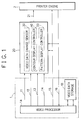
- Each of the embodiments respectively shown in Figs. 1 and 8 includes a printer engine 2 for receiving information from a host computer printing out the information on a sheet of printing paper and a printer controller 1 for controlling operation of the printer engine 2.
- a video data processor 20 in addition to the printer controller 1, there is arranged a video data processor 20.
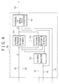
- the processor 20 includes a video data change point sensor 30 for sensing a change point of video data according to a video signal 13 received from the printer controller 1, a contour display controller for operating on the basis of the sensed data change point and thereby producing data representing a contour, and a pattern display controller 50 including pattern storage sections 511 to 51 n for keeping therein a plurality of pattern data items received from an external device and a pattern selector 53 for selecting a predetermined display pattern from the pattern storage sections 511 to 51 n .
- the video data processor 20 of Fig. 2 further includes a logic circuit 25 as a modulated video signal generator for operating on the basis of data created from the contour display controller 40 and data produced from the pattern display controller 50 for outputting therefrom a modulated video signal 17 in a predetermined format.
- a logic circuit 25 as a modulated video signal generator for operating on the basis of data created from the contour display controller 40 and data produced from the pattern display controller 50 for outputting therefrom a modulated video signal 17 in a predetermined format.
- the printer controller 1 includes a video processor 1A and a video data storage 1B.
- the processor 1A receives print data from a host computer to generate therefrom drawing data for each dot in conformity with resolution of the printer engine 2 so as to store the attained data in the storage 1B.
- a vertical synchronizing (sync) signal 15 is fed to the video data processor 20 and the printer engine 2.
- a horizontal synchronizing signal 16 is delivered from the printer engine 2 to the video processor 1A and the video data processor 20.
- Video data which is generated by the video processor 1A and which is then stored in the video data storage 1B is transformed into a video signal 13 in association with the horizontal synchronizing signal 16 from the printer engine 2 and the video synchronizing signal 14.
- the video signal 13 is sent to the video data processor 20.
- the video data processor 20 conducts a video data processing for the video signal 13 from the video processor 1A to produce a video signal 21 to be fed to the printer engine 2.
- the contents of the processing of the video data processor 20 will now be described by reference to Figs. 1 to 3.
- the video data processor 20 includes as described above the video data change point sensor 30, the contour display controller 40, and the pattern display controller 50. Transmitted to the controllers 40 and 50 is a select signal 24 created by an address decoder 23 according to information on the data bus 12 for the data write operation and the address bus 11 specifying an internal storage address.
- the sensor 30 receives the video signal 13 from the video processor 1A, the sensor 30 produces therefrom a video change point sense signal 31 indicating a point where print data alters from white to black.
- the sense signal 31 is transmitted to the contour display controller 40 and the pattern display controller 50.
- Contour data 44 created by the contour display controller 40 and pattern data 54 generated by the pattern display controller 50 are combined with each other into a modulated video signal 17 by the logical AND circuit 25 of the video data processor 20 of which the detailed structure is shown in Fig. 2.
- the obtained signal 17 is fed to a logical OR circuit 26 receiving the video signal 13 from the video processor 1A.
- a video signal 21 in which the modulation is carried out only for print data.
- the signal is sent to the printer engine 2.
- the contour display controller 40 includes as shown in Fig. 3 a pulse width storage 41, a counter 42, and an edge black data generation controller 43.
- the video change point sense signal 31 described above is fed to the controller 43.
- data representing a contour is generated using the change point as the starting point of data generation.
- the counter 42 reads information from the pulse width storage 41 and starts its count operation in synchronism with the video synchronizing signal 14.
- the counter 42 sends a signal to stop transmission of black data to the edge black data generation controller 43.
- the controller 43 terminates transmitting contour data 44.
- the controller 50 includes a pattern storage 51, a parallel-to-serial data converter 52, and a pattern selector 53.
- the pattern storage 51 includes n storage sections 511 to 51 n . It is possible to register m-bit information to each storage section. In this embodiment, for convenience of description, there are used eight pattern storage sections each having a pattern length of eight bits.
- the data bus 12 and the select signal 24 are connected to the pattern storage 51. Before the video data processing is conducted or after the printer is powered, pattern data is sequentially registered to the storage 51.
- the vertical synchronizing signal 15 and the horizontal synchronizing signal 16 Supplied to the pattern selector 53 are the vertical synchronizing signal 15 and the horizontal synchronizing signal 16. Patterns are respectively selected from the storage sections 1 to 8 for each scan line. In this selecting operation, the sequential number of pattern selection is reset for the pattern storage 51 according to the vertical synchronizing signal 15. Thereafter, when the signal 15 is inputted, the selecting operation is carried out beginning at the first pattern again. Consequently, even when identical data is printed a plurality of times, there can be conducted the same pattern data processing.
- the parallel-to-serial data converter 52 reads, on receiving the video synchronization signal 14, 8-bit parellel pattern data from the pattern storage 51 selected in the above procedure and then converts the parallel data into serial data at timing synchronized with the signal 14.
- the objective data to be stored therein is changed over in synchronism with the horizontal synchronizing signal 16. Consequently, when processing the same scanning line, pattern data selected by the pattern selector 53 is repeatedly outputted to the pattern storage 51.
- a video synchronizing signal 14 indicates a dot clock
- a horizontal synchronizing signal 16 denotes a signal outputted from the printer engine 2
- a video signal 13 represents black print data effective at a low level.
- the signal 13 is valid from t6 to t17.
- Contour data 44 namely, a signal produced from the contour display controller 40 designates data therefrom. That is, beginning at a rising point (a falling point in Fig. 5) of the t6 state where the video signal 13 becomes effective, the value of the pulse count kept in the pulse width storage 41 is outputted therefrom.
- the storage 41 of the contour display controller 40 is beforehand loaded with dot width information. In this example, two-dot contour data 44 is outputted from the controller 40.
- pattern data 54 namely, a signal outputted from the pattern display controller 50 represents pattern data therefrom.
- a low-level signal indicates black data.
- a video signal 21 is delivered from the video data processor 20 to the printer engine 2.
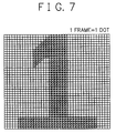
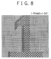
- Fig. 6 shows an example of data stored in the pattern storage 51 in the form of a matrix (eight dots by eight dots).
- Figs. 7 and 8 show printout examples of the data.
- pattern data stored in the contour display controller 40 and the pattern data display controller 50 are externally written therein via the data bus 12 according to the address bus 11.
- ROM read-only memory
- the embodiment includes the contour display controller 40 for controlling the contour display operation and the pattern display controller 50 for keeping therein the pattern data 54 in the matrix form (m dots by n dots) and controlling the output data.
- the contour display controller 40 for controlling the contour display operation
- the pattern display controller 50 for keeping therein the pattern data 54 in the matrix form (m dots by n dots) and controlling the output data.
- consecutive dot data can be represented as a regular pattern.
- the amount of saved toner can be remarkably increased.
- changing pattern data in association with resolution of the printer a uniform printout result can be attained independently of the resolution.
- controlling the contour width the image of original data can be kept unchanged.
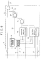
- Fig. 9 shows an alternative embodiment in accordance with the present invention.
- a logic circuit 27 operative in response to an external instruction for selecting either one of a received video signal 13 and a modulated video signal 19.
- an enable signal 18 to decide whether or not the thinning out operation is conducted for the video data is fed to the logic circuit 27.
- the other constituent components are the same as those of the embodiment shown in Fig. 1.
- the contour display controller for controlling the contour display operation and the pattern display controller for beforehand keeping therein pattern data and controlling the output operation. Consequently, as means of saving the amount of toner consumption, successive dot data can be represented in the form of a regular pattern. Namely, preparing various patterns in advance, the toner consumption can be considerably saved. Furthermore, changing the pattern data depending on resolution of the printer, a uniform printout result can be attained independently of the resolution. Moreover, the image of original data can be kept remained by controlling the contour width.
- the apparatus in addition to the advantageous effect of operation above, the apparatus can be set to conduct an ordinary printing operation, which makes it possible to provide a printing apparatus and a printing method applicable to various purposes.
Landscapes
- Engineering & Computer Science (AREA)
- Physics & Mathematics (AREA)
- Multimedia (AREA)
- Signal Processing (AREA)
- General Engineering & Computer Science (AREA)
- General Physics & Mathematics (AREA)
- Theoretical Computer Science (AREA)
- Optics & Photonics (AREA)
- Dot-Matrix Printers And Others (AREA)
- Fax Reproducing Arrangements (AREA)
- Facsimile Image Signal Circuits (AREA)
Applications Claiming Priority (3)
| Application Number | Priority Date | Filing Date | Title |
|---|---|---|---|
| JP5347901A JP2669336B2 (ja) | 1993-12-24 | 1993-12-24 | 印刷装置 |
| JP347901/93 | 1993-12-24 | ||
| JP34790193 | 1993-12-24 |
Publications (3)
| Publication Number | Publication Date |
|---|---|
| EP0661663A2 true EP0661663A2 (de) | 1995-07-05 |
| EP0661663A3 EP0661663A3 (de) | 1996-01-17 |
| EP0661663B1 EP0661663B1 (de) | 2000-03-08 |
Family
ID=18393376
Family Applications (1)
| Application Number | Title | Priority Date | Filing Date |
|---|---|---|---|
| EP94120316A Expired - Lifetime EP0661663B1 (de) | 1993-12-24 | 1994-12-21 | Druckvorrichtung und -verfahren die über eine Tonersparfunktion verfügen |
Country Status (6)
| Country | Link |
|---|---|
| US (1) | US5862306A (de) |
| EP (1) | EP0661663B1 (de) |
| JP (1) | JP2669336B2 (de) |
| AU (1) | AU686273B2 (de) |
| CA (1) | CA2138918C (de) |
| DE (1) | DE69423325T2 (de) |
Families Citing this family (1)
| Publication number | Priority date | Publication date | Assignee | Title |
|---|---|---|---|---|
| JP4846941B2 (ja) * | 2001-08-30 | 2011-12-28 | 富士通株式会社 | 印刷制御装置、およびプログラム |
Family Cites Families (14)
| Publication number | Priority date | Publication date | Assignee | Title |
|---|---|---|---|---|
| US4672431A (en) * | 1983-10-26 | 1987-06-09 | Harris Corporation | Contour correction system when one color signal is low |
| US4665432A (en) * | 1984-01-30 | 1987-05-12 | Sharp Kabushiki Kaisha | Video contour correction system |
| JPS60172548A (ja) * | 1984-02-20 | 1985-09-06 | Oki Electric Ind Co Ltd | ドットプリンタ |
| US5089811A (en) * | 1984-04-16 | 1992-02-18 | Texas Instruments Incorporated | Advanced video processor having a color palette |
| JPH0739191B2 (ja) * | 1988-02-29 | 1995-05-01 | 沖電気工業株式会社 | ドットマトリクス式プリンタ |
| JPH02144574A (ja) * | 1988-11-25 | 1990-06-04 | Toshiba Corp | 電子写真方式のプリンタ装置 |
| KR0133515B1 (ko) * | 1990-07-21 | 1998-04-22 | 구자홍 | 수직/수평 윤곽 보정시스템 |
| US5353387A (en) * | 1990-09-10 | 1994-10-04 | Mannesmann Aktiengesellschaft | Process for reducing the quantity of ink applied to recording substrates by ink printing devices to prevent image degradation |
| US5270728A (en) * | 1991-04-17 | 1993-12-14 | Hewlett-Packard Company | Raster imaging device speed-resolution product multiplying method and resulting pixel image data structure |
| JP2835886B2 (ja) * | 1991-05-10 | 1998-12-14 | キヤノン株式会社 | ファクシミリ装置 |
| KR940011878B1 (ko) * | 1991-12-27 | 1994-12-27 | 삼성전자 주식회사 | 윤곽보정장치 |
| US5483625A (en) * | 1993-04-26 | 1996-01-09 | Hewlett-Packard Company | Method and apparatus for adjusting density in digital images |
| JPH07107280A (ja) * | 1993-10-06 | 1995-04-21 | Matsushita Electric Ind Co Ltd | 画像形成装置 |
| JPH07123267A (ja) * | 1993-10-25 | 1995-05-12 | Canon Inc | カラー画像形成装置 |
-
1993
- 1993-12-24 JP JP5347901A patent/JP2669336B2/ja not_active Expired - Lifetime
-
1994
- 1994-12-21 DE DE69423325T patent/DE69423325T2/de not_active Expired - Fee Related
- 1994-12-21 EP EP94120316A patent/EP0661663B1/de not_active Expired - Lifetime
- 1994-12-22 CA CA002138918A patent/CA2138918C/en not_active Expired - Fee Related
- 1994-12-22 AU AU81673/94A patent/AU686273B2/en not_active Ceased
-
1997
- 1997-11-01 US US08/966,668 patent/US5862306A/en not_active Expired - Fee Related
Also Published As
| Publication number | Publication date |
|---|---|
| CA2138918C (en) | 2000-02-08 |
| EP0661663A3 (de) | 1996-01-17 |
| CA2138918A1 (en) | 1995-06-25 |
| JPH07186450A (ja) | 1995-07-25 |
| EP0661663B1 (de) | 2000-03-08 |
| DE69423325D1 (de) | 2000-04-13 |
| AU686273B2 (en) | 1998-02-05 |
| JP2669336B2 (ja) | 1997-10-27 |
| DE69423325T2 (de) | 2000-11-09 |
| US5862306A (en) | 1999-01-19 |
| AU8167394A (en) | 1995-06-29 |
Similar Documents
| Publication | Publication Date | Title |
|---|---|---|
| JPH0640080A (ja) | プリンタ | |
| EP0506381A2 (de) | Bildverarbeitungsgerät | |
| US5381522A (en) | Image processing apparatus and method | |
| US5742317A (en) | Image processing apparatus and recording apparatus | |
| US5877865A (en) | Image processing apparatus and method for printing data described in a page description language | |
| EP0457572B1 (de) | Druckdatenausgangsverfahren und -gerät | |
| US5894546A (en) | Image processing apparatus for converting multivalued image into binary image and outputting binary image | |
| JP2001213015A (ja) | 画像記録装置 | |
| EP0661663B1 (de) | Druckvorrichtung und -verfahren die über eine Tonersparfunktion verfügen | |
| EP0919949B1 (de) | System und Verfahren zur Steuerung einer anwendungsspezifisch integrierten Schaltung | |
| US5606656A (en) | Image data processing unit for forming a plurality of identical images in a single output image area | |
| KR100208696B1 (ko) | 래스터 이미지를 고화질로 인쇄하는 프린터 및 방법 | |
| US6628289B1 (en) | Rendering apparatus and method, and storage medium | |
| US5347597A (en) | Image scaling for thermal printers and the like | |
| US4985852A (en) | Method of and apparatus for driving a dot array recorder | |
| JP2647917B2 (ja) | 画像処理装置 | |
| JP3233970B2 (ja) | 画像処理方法及び装置 | |
| JP3184639B2 (ja) | 画像処理装置及び方法 | |
| JPH04301470A (ja) | 画像処理装置 | |
| JP2721347B2 (ja) | 画像処理装置 | |
| JPH04301465A (ja) | 記録装置 | |
| JPS63290460A (ja) | 画像表示記録装置 | |
| JPH05211593A (ja) | 印刷装置 | |
| JPH06245055A (ja) | 印刷装置及びその方法 | |
| JPH01183969A (ja) | ビデオ・プリンタ |
Legal Events
| Date | Code | Title | Description |
|---|---|---|---|
| PUAI | Public reference made under article 153(3) epc to a published international application that has entered the european phase |
Free format text: ORIGINAL CODE: 0009012 |
|
| AK | Designated contracting states |
Kind code of ref document: A2 Designated state(s): DE FR GB IT NL SE |
|
| PUAL | Search report despatched |
Free format text: ORIGINAL CODE: 0009013 |
|
| AK | Designated contracting states |
Kind code of ref document: A3 Designated state(s): DE FR GB IT NL SE |
|
| 17P | Request for examination filed |
Effective date: 19951207 |
|
| GRAG | Despatch of communication of intention to grant |
Free format text: ORIGINAL CODE: EPIDOS AGRA |
|
| 17Q | First examination report despatched |
Effective date: 19990406 |
|
| GRAG | Despatch of communication of intention to grant |
Free format text: ORIGINAL CODE: EPIDOS AGRA |
|
| GRAG | Despatch of communication of intention to grant |
Free format text: ORIGINAL CODE: EPIDOS AGRA |
|
| GRAH | Despatch of communication of intention to grant a patent |
Free format text: ORIGINAL CODE: EPIDOS IGRA |
|
| GRAH | Despatch of communication of intention to grant a patent |
Free format text: ORIGINAL CODE: EPIDOS IGRA |
|
| GRAH | Despatch of communication of intention to grant a patent |
Free format text: ORIGINAL CODE: EPIDOS IGRA |
|
| GRAH | Despatch of communication of intention to grant a patent |
Free format text: ORIGINAL CODE: EPIDOS IGRA |
|
| GRAA | (expected) grant |
Free format text: ORIGINAL CODE: 0009210 |
|
| AK | Designated contracting states |
Kind code of ref document: B1 Designated state(s): DE FR GB IT NL SE |
|
| REF | Corresponds to: |
Ref document number: 69423325 Country of ref document: DE Date of ref document: 20000413 |
|
| ITF | It: translation for a ep patent filed | ||
| ET | Fr: translation filed | ||
| PLBE | No opposition filed within time limit |
Free format text: ORIGINAL CODE: 0009261 |
|
| STAA | Information on the status of an ep patent application or granted ep patent |
Free format text: STATUS: NO OPPOSITION FILED WITHIN TIME LIMIT |
|
| 26N | No opposition filed | ||
| REG | Reference to a national code |
Ref country code: GB Ref legal event code: IF02 |
|
| PGFP | Annual fee paid to national office [announced via postgrant information from national office to epo] |
Ref country code: SE Payment date: 20061206 Year of fee payment: 13 |
|
| PGFP | Annual fee paid to national office [announced via postgrant information from national office to epo] |
Ref country code: FR Payment date: 20061208 Year of fee payment: 13 |
|
| PGFP | Annual fee paid to national office [announced via postgrant information from national office to epo] |
Ref country code: DE Payment date: 20061214 Year of fee payment: 13 |
|
| PGFP | Annual fee paid to national office [announced via postgrant information from national office to epo] |
Ref country code: NL Payment date: 20061217 Year of fee payment: 13 |
|
| PGFP | Annual fee paid to national office [announced via postgrant information from national office to epo] |
Ref country code: GB Payment date: 20061220 Year of fee payment: 13 |
|
| PGFP | Annual fee paid to national office [announced via postgrant information from national office to epo] |
Ref country code: IT Payment date: 20061231 Year of fee payment: 13 |
|
| EUG | Se: european patent has lapsed | ||
| GBPC | Gb: european patent ceased through non-payment of renewal fee |
Effective date: 20071221 |
|
| NLV4 | Nl: lapsed or anulled due to non-payment of the annual fee |
Effective date: 20080701 |
|
| PG25 | Lapsed in a contracting state [announced via postgrant information from national office to epo] |
Ref country code: SE Free format text: LAPSE BECAUSE OF NON-PAYMENT OF DUE FEES Effective date: 20071222 Ref country code: DE Free format text: LAPSE BECAUSE OF NON-PAYMENT OF DUE FEES Effective date: 20080701 |
|
| REG | Reference to a national code |
Ref country code: FR Ref legal event code: ST Effective date: 20081020 |
|
| PG25 | Lapsed in a contracting state [announced via postgrant information from national office to epo] |
Ref country code: NL Free format text: LAPSE BECAUSE OF NON-PAYMENT OF DUE FEES Effective date: 20080701 |
|
| PG25 | Lapsed in a contracting state [announced via postgrant information from national office to epo] |
Ref country code: GB Free format text: LAPSE BECAUSE OF NON-PAYMENT OF DUE FEES Effective date: 20071221 |
|
| PG25 | Lapsed in a contracting state [announced via postgrant information from national office to epo] |
Ref country code: FR Free format text: LAPSE BECAUSE OF NON-PAYMENT OF DUE FEES Effective date: 20071231 |
|
| PG25 | Lapsed in a contracting state [announced via postgrant information from national office to epo] |
Ref country code: IT Free format text: LAPSE BECAUSE OF NON-PAYMENT OF DUE FEES Effective date: 20071221 |