EP0655611A1 - Behälter zur Aufnahme von Schüttgut - Google Patents
Behälter zur Aufnahme von Schüttgut Download PDFInfo
- Publication number
- EP0655611A1 EP0655611A1 EP94115100A EP94115100A EP0655611A1 EP 0655611 A1 EP0655611 A1 EP 0655611A1 EP 94115100 A EP94115100 A EP 94115100A EP 94115100 A EP94115100 A EP 94115100A EP 0655611 A1 EP0655611 A1 EP 0655611A1
- Authority
- EP
- European Patent Office
- Prior art keywords
- container
- outlet
- cone
- double cone
- funnel
- Prior art date
- Legal status (The legal status is an assumption and is not a legal conclusion. Google has not performed a legal analysis and makes no representation as to the accuracy of the status listed.)
- Granted
Links
- 239000013590 bulk material Substances 0.000 title claims abstract description 7
- 238000007789 sealing Methods 0.000 claims abstract description 13
- 239000000463 material Substances 0.000 claims description 20
- 238000005303 weighing Methods 0.000 claims description 9
- 230000007704 transition Effects 0.000 claims description 2
- 229920001971 elastomer Polymers 0.000 description 3
- 239000005060 rubber Substances 0.000 description 3
- 238000011161 development Methods 0.000 description 2
- 230000018109 developmental process Effects 0.000 description 2
- 239000003999 initiator Substances 0.000 description 2
- 238000004519 manufacturing process Methods 0.000 description 2
- 206010053648 Vascular occlusion Diseases 0.000 description 1
- 238000009825 accumulation Methods 0.000 description 1
- 230000015572 biosynthetic process Effects 0.000 description 1
- 238000010276 construction Methods 0.000 description 1
- 238000000034 method Methods 0.000 description 1
Images

Classifications
-
- G—PHYSICS
- G01—MEASURING; TESTING
- G01G—WEIGHING
- G01G13/00—Weighing apparatus with automatic feed or discharge for weighing-out batches of material
- G01G13/003—Details; specially adapted accessories
- G01G13/006—Container supply or discharge mechanism
-
- B—PERFORMING OPERATIONS; TRANSPORTING
- B65—CONVEYING; PACKING; STORING; HANDLING THIN OR FILAMENTARY MATERIAL
- B65D—CONTAINERS FOR STORAGE OR TRANSPORT OF ARTICLES OR MATERIALS, e.g. BAGS, BARRELS, BOTTLES, BOXES, CANS, CARTONS, CRATES, DRUMS, JARS, TANKS, HOPPERS, FORWARDING CONTAINERS; ACCESSORIES, CLOSURES, OR FITTINGS THEREFOR; PACKAGING ELEMENTS; PACKAGES
- B65D90/00—Component parts, details or accessories for large containers
- B65D90/54—Gates or closures
- B65D90/62—Gates or closures having closure members movable out of the plane of the opening
- B65D90/626—Gates or closures having closure members movable out of the plane of the opening having a linear motion
-
- G—PHYSICS
- G01—MEASURING; TESTING
- G01G—WEIGHING
- G01G13/00—Weighing apparatus with automatic feed or discharge for weighing-out batches of material
- G01G13/16—Means for automatically discharging weigh receptacles under control of the weighing mechanism
Definitions
- the invention relates to a container for receiving bulk goods.
- Container scales are used for batch-wise weighing of bulk goods. These container scales must be equipped with a closure on the bottom, which keeps the weighing container closed while the bulk goods are being metered in and opens an outlet after the weighing process, which ensures residue-free emptying.
- Rotary flaps, flat slides or pinch valves are used for this purpose.
- a disadvantage of rotary flaps is that not the entire outlet cross-section of the bottom opening is available for the outlet, but rather the drive shaft or the leaf thickness of the flap, as a disruptive element, negatively influences the outlet.
- Pinch valves have a disadvantageous opening behavior because the rubber sleeve loses resilience with age. The high weight of the three closure elements mentioned is disadvantageous.
- a container with a cone closure is known.
- This cone closure is designed as a double cone and is in the closed state on a sealing element.
- This sealing element is a rubber-like material and is arranged in the outlet pipe of the container.
- the double cone is pulled upwards, with the double cone first having to cover a large distance until it dips into the interior of the container and releases a larger annular gap there.
- a disadvantage of this system is that material can settle on or on the sealing surfaces in the outlet pipe, because the sealing surfaces lie in the flow shadow of the bulk material being discharged. Soft sealing elements are required so that the container can be reliably closed with the double cone despite material deposits.
- the known closure has a greater manufacturing cost and a greater overall height.
- This closing cone which is designed as a double cone, closes the outlet from above and is additionally supported by the dynamic pressure of the bulk material.
- the closure When the closure is opened, the entire container outlet cross-section is released at a corresponding lifting height, so that the product can flow out unhindered. This prevents the formation of bridges and prevents deposits on the closure elements.
- a major advantage of the invention is that the double cone arranged in the container outlet is arranged in the extension area of the container. If it is pulled upwards to open it, the material can flow out almost unhindered. With a relatively small stroke movement, the annular gap is already so large that the cross section of the annular gap corresponds to the passage cross section of the cylindrical outlet.
- Another advantage of the invention is that the sealing surfaces, both on the container and on the double cone, are arranged in the strongly activated outlet zone, i. H. the material flows past these points at high speed. Accumulation and caking of material are completely excluded in this area. This makes it possible to ensure reliable sealing of the container without additional sealing elements such as rubbers or rubber seals or other soft sealing elements.
- the device for weighing bulk goods consists of a container 1 which has a plurality of material inlet nozzles 2 on a tightly closing lid 3.
- the material inlet connections 2 are connected via flexible sleeves 4 to material supply openings 5 which are provided with quick-closing flaps 6, so that the material supply can be switched off suddenly when a desired weight value is reached.
- the container also has a pneumatic knocker or vibrator 7 for complete emptying.
- the outlet 8 of the container is connected to a flexible sleeve 9, to a downpipe 10 below it, or to a collecting vessel.
- Container 1 is screwed onto a firmly anchored weighing frame 12, on which one or more load cells 11 are attached. Changes in weight of the system are transmitted to an MSR system 17 via the pressure load cells 11.
- the outlet closing body is designed as a double cone 13 which is movable inside the container and which is connected to a pneumatic cylinder 15 via a pull rod 14.
- Proximity initiators 16 are attached to the pneumatic cylinder 15 and signal the MSR system 17 the state of the container outlet.
- the double cone 13 remains in the closed position.
- the double cone 13 is brought into a position which does not disturb the outflow of the bulk material by means of the pneumatic cylinder 15 and the rod 14.
- the double cone 13 is flushed with material on all sides when the bulk material runs out inside the container, so that no caking and residues can form on the double cone 13 and on the outlet.
- the double cone counteracts 13 bridges inside the container.
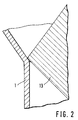
- the sealing area between the container and the double cone is shown in a detailed representation.
- the double cone lies directly on the narrowest area of the container cone on the inside wall of the container.
- the lower cone of the closure element has a slightly obtuse angle than the angle of inclination of the cone of the container. This prevents the double cone 13 from jamming.
Landscapes
- Physics & Mathematics (AREA)
- General Physics & Mathematics (AREA)
- Engineering & Computer Science (AREA)
- Mechanical Engineering (AREA)
- Filling Or Emptying Of Bunkers, Hoppers, And Tanks (AREA)
- Basic Packing Technique (AREA)
- Closures For Containers (AREA)
- Transition And Organic Metals Composition Catalysts For Addition Polymerization (AREA)
Abstract
Description
- Die Erfindung betrifft einen Behälter zur Aufnahme von Schüttgut.
- Beim chargenweisen Verwiegen von Schüttgütern werden Behälterwaagen eingesetzt. Diese Behälterwaagen müssen mit einem bodenseitigen Verschluß ausgerüstet sein, welcher den Wiegebehälter während des Zudosierens der Schüttgüter geschlossen hält und nach Beendigung der Verwiegung einen Auslaß öffnet, der eine rückstandsfreie Entleerung gewährleistet. Zu diesem Zweck werden Drehklappen, Flachschieber oder Quetschventile eingesetzt. Bei Drehklappen ist von Nachteil, daß für den Auslauf nicht der gesamte Auslaufquerschnitt der Bodenöffnung zur Verfügung steht, sondern die Antriebswelle bzw. die Blattdicke der Klappe als störendes Element den Auslauf negativ beeinflußt. Bei Flachschiebern ist von Nachteil, daß sich in der Führung des Schieberblattes Anbackungen und Rückstände bilden und das Verschlußelement nicht restlos dicht ist. Quetschventile weisen ein nachteiliges Öffnungsverhalten auf, da die Gummimanschette mit zunehmendem Alter an Ruckstellvermögen einbüßt. Für die drei genannten Verschlußelemente ist ihr hohes Gewicht von Nachteil.
- Man könnte nun die genannten Verschlußarten bezüglich Gewicht und Verschlußverhalten optimieren, z. B. durch Verringerung der Toleranzen oder Einsatz anderer Werkstoffe. Dies ist aber einmal kostenaufwendig in der Herstellung, es würde die Vorrichtung daher verteuern, zum anderen dürften sich Probleme im Betrieb einstellen.
- Aus der DE-OS 35 15 367 ist ein Behälter mit einem Kegelverschluß bekannt. Dieser Kegelverschluß ist als Doppelkegel ausgeführt und liegt im geschlossenen Zustand an einem Dichtelement an. Dieses Dichtelement ist ein gummiartiges Material und im Auslaufrohr des Behälters angeordnet. Zum Öffnen des Behälters und zum Dosieren des im Behälter enthaltenen Materials wird der Doppelkegel nach oben gezogen, wobei zunächst der Doppelkegel einen großen Verschlußweg zurücklegen muß, bis er in den Innenraum des Behälters eintaucht und dort einen größeren Ringspalt freigibt.
- Ein Nachteil dieses Systems liegt darin, daß sich an bzw. auf den Dichtflächen im Auslaufrohr Material absetzen kann, weil die Dichtflächen im Strömungsschatten des auslaufenden Schüttgutes liegen. Damit trotz Materialablagerungen ein zuverlässiges Schließen des Behälters mit dem Doppelkegel möglich ist, sind weiche Dichtungselemente erforderlich. Darüber hinaus weist der bekannte Verschluß einen größeren Fertigungsaufwand und eine größere Bauhöhe auf.
- Es ist auch bekannt, einen Kegel zum Verschließen eines Behälters von unten her an die Auslauföffnung heranzuführen. Ein Nachteil dieses Systems ist darin zu sehen, daß unterhalb des Kegels der Querschnitt wieder erweitert werden muß, damit zumindest ein Ringspalt zum Abfließen des Behälterinhalts entsteht. Diese Querschnittserweiterung erfordert einen baulichen Mehraufwand. Außerdem befindet sich der Kegel im geöffneten Zustand als ein störendes Element im Materialfluß.
- Es ist somit Aufgabe der Erfindung, eine Vorrichtung der eingangs genannten Art dahingehend zu verbessern, daß ein einfacher, billiger und leicht zu öffnender bzw. zu schließender Verschluß geschaffen wird, der insbesondere ein geringes Gewicht aufweist. Erfindungsgemäß wird diese Aufgabe dadurch gelöst, daß der Doppelkegel den Behälter unmittelbar am Behälterkonusübergang zum Auslauf abdichtet und damit verschließt und damit der engste Bereich des Behälterkonusses als Dichtfläche ausgestaltet ist.
- Dieser als Doppelkegel ausgebildete Schließkörper verschließt den Auslaß von oben her und wird zusätzlich vom Staudruck des Schüttguts unterstützt. Beim Öffnen des Verschlusses wird bei entsprechender Hubhöhe der gesamte Behälterauslaufquerschnitt freigegeben, so daß das Produkt ungehindert ausströmen kann. Brückenbildung wird so vorgebeugt, Anlagerungen an den Verschlußelementen werden verhindert.
- Ein wesentlicher Vorteil der Erfindung ist darin zu sehen, daß der im Behälterauslauf angeordnete Doppelkegel im Erweiterungsbereich des Behälters angeordnet ist. Wird dieser zum Öffnen nach oben gezogen, so kann das Material nahezu ungehindert ausfließen. Der Ringspalt wird bei einer relativ kleinen Hubbewegung bereits so groß, daß der Querschnitts des Ringspalts dem Durchlaßquerschnitts des zylindrischen Ausgangs entspricht.
- Ein weiterer Vorteil der Erfindung ist darin zu sehen, daß die Dichtflächen, und zwar sowohl am Behälter als auch am Doppelkegel in der stark aktivierten Auslaufzone angeordnet sind, d. h. an diesen Stellen das Material mit hoher Geschwindigkeit vorbeiströmt. Anlagerungen und Anbackungen von Material sind in diesem Bereich völlig ausgeschlossen. Damit besteht die Möglichkeit, ohne zusätzliche Dichtelement wie Gummis oder Gummidichtungen oder andere weiche Dichtelemente eine zuverlässige Abdichtung des Behälters zu gewährleisten.
- Vorteilhafte Weiterbildungen der Erfindung ergeben sich aus den Unteransprüchen.
- Diese und weitere Merkmale von bevorzugten Weiterbildungen der Erfindung gehen außer aus den Ansprüchen auch aus der Beschreibung und den Zeichnungen hervor, wobei die einzelnen Merkmale jeweils für sich allein oder zu mehreren in Form von Unterkombinationen bei der Ausführungsform der Erfindung und auf anderen Gebieten verwirklicht sein und vorteilhafte sowie für sich schutzfähige Ausführungen darstellen können, für die hier Schutz beansprucht wird.
- Die Erfindung wird nachfolgend anhand eines Ausführungsbeispiels näher erläutert. Es zeigt:
- Figur 1 eine Darstellung der Verwiegeeinrichtung.
- Figur 2 Detaildarstellung des Verschlusses.
- Die Vorrichtung zur Verwiegung von Schüttgütern besteht aus einem Behälter 1, der mehrere Materialeinlaufstutzen 2 an einem dicht schließenden Deckel 3 aufweist.
- Die Materialeinlaufstutzen 2 sind über flexible Manschetten 4 mit Materialzuführungsöffnungen 5 verbunden, die mit Schnellschlußklappen 6 versehen sind, um somit die Materialzufuhr bei Erreichen eines gewünschten Gewichtswertes schlagartig abstellen zu können. Weiter weist der Behälter einen pneumatischen Klopfer oder Rüttler 7 zur restlosen Entleerung auf. Der Auslauf 8 des Behälters ist mit einer flexiblen Manschette 9, mit einem darunter befindlichen Fallrohr 10 oder einem Sammelgefäß verbunden.
- Behälter 1 ist auf einem fest verankerten Wiegerahmen 12, auf dem eine oder mehrere Druckmeßdosen 11 befestigt sind, angeschraubt. Gewichtsänderungen des Systems werden über die Druckmeßdosen 11 an ein MSR-System 17 übermittelt. Der Auslaßschließkörper ist als im Behälterinneren beweglicher Doppelkegel 13 ausgebildet, der über eine Zugstange 14 mit einem Pneumatikzylinder 15 verbunden ist. Am Pneumatikzylinder 15 sind Näherungsinitiatoren 16 angebracht, die dem MSR-System 17 den Zustand des Behälterauslaufes signalisieren.
- Während des Einwiegens verharrt der Doppelkegel 13 in Schließstellung.
- Zum Entleeren des Behälters 1 wird der Doppelkegel 13 mittels des Pneumatikzylinders 15 und der Stange 14 in eine den Ausfluß des Schüttguts nicht störende Position gebracht. Der Doppelkegel 13 wird so beim Auslaufen des Schüttguts im Behälterinneren allseitig von Material umspült, so daß sich keine Anbackungen und Rückstände am Doppelkegel 13 und am Auslaß bilden können. Beim Öffnen des Auslasses wirkt Doppelkegel 13 Brückenbildungen im Behälterinneren entgegen.
- In Figur 2 ist in einer Detaildarstellung der Dichtbereich zwischen Behälter und Doppelkegel dargestellt. Der Doppelkegel liegt unmittelbar am engsten Bereich des Behälterkonusses an der Behälterinnenwand an. Der untere Kegel des Verschlußelements weist einen geringfügig stumpferen Winkel auf als der Neigungswinkel des Behälterkonusses. Damit wird ein Klemmen des Doppelkegels 13 verhindert.
-
- 1
- Behälter
- 2
- Materialeinlaufstutzen
- 3
- Deckel
- 4
- flexible Manschetten
- 5
- Materialzuführungsöffnungen
- 6
- Schnellschlußklappen
- 7
- Rüttler
- 8
- Auslauf
- 9
- flexible Manschette
- 10
- Fallrohr
- 11
- Druckmeßdosen
- 12
- Wiegerahmen
- 13
- Doppelkegel
- 14
- Stange
- 15
- Pneumatikzylinder
- 16
- Näherungsinitiatoren
- 17
- MSR-System
Claims (11)
- Behälter zur Aufnahme von Schüttgut, der wenigstens einen Materialeinlaufstutzen (2) aufweist und über einen Deckel (3) und einen dicht schließenden Auslaß verfügt, wobei der Behälter im unteren Bereich trichterförmig ausgestaltet ist und der Auslauf näherungsweise konzentrisch zu dem trichterförmigen Bereich angeordnet ist und wobei ein Auslaßschließkörper in Form eines Doppelkegels (13) im Behälterinneren axialbeweglich angeordnet ist, dadurch gekennzeichnet, daß der Doppelkegel den Behälter unmittelbar am Behälterkonusübergang zum Auslauf abdichtet und verschließt und damit der engste Bereich des Behälterkonusses als Dichtfläche ausgestaltet ist.
- Behälter nach Anspruch 1, dadurch gekennzeichnet, daß das im Behälter enthaltene Schüttgut gravimetrisch erfaßbar ist.
- Behälter nach einem der vorhergehenden Ansprüche, dadurch gekennzeichnet, daß der Neigungswinkel des unteren Doppelkegels des Auslaßschließkörpers näherungsweise dem Neigungswinkel des Auslauftrichters des Behälters entspricht oder geringfügig größer ist.
- Vorrichtung nach einem oder mehreren der vorgenannten Ansprüche, dadurch gekennzeichnet, daß der Doppelkegel (13) im Inneren des Behälters über eine Stange (14) betätigt wird.
- Vorrichtung nach Anspruch 4, dadurch gekennzeichnet, daß ein Pneumatikzylinder (15) die Stange (14) auf- und abbewegt.
- Vorrichtung nach einem oder mehreren der vorgenannten Ansprüche, dadurch gekennzeichnet, daß die Stellung des Absperrorgans über Näherungsinitiatoren (16) signalisiert wird.
- Vorrichtung nach einem oder mehreren der vorgenannten Ansprüche, dadurch gekennzeichnet, daß die Materialeinlaufstutzen (2) über flexible Manschetten (4) mit den Materialzuführungsöffnungen (5) verbunden sind.
- Vorrichtung nach einem oder mehreren der vorgenannten Ansprüche, dadurch gekennzeichnet, daß die Materialzuführungsöffnungen (5) mit Schnellschlußklappen (6) versehen sind.
- Vorrichtung nach einem oder mehreren der vorgenannten Ansprüche, dadurch gekennzeichnet, daß am Behälter (1) ein Rüttler (7) befestigt ist.
- Vorrichtung nach einem oder mehreren der vorgenannten Ansprüche, dadurch gekennzeichnet, daß am Auslauf (8) des Behälters eine flexible Manschette (9) mit einem darunter befindlichen Fallrohr (10) oder einem Sammelbehälter befestigt ist.
- Vorrichtung nach einem oder mehreren der vorgenannten Ansprüche, dadurch gekennzeichnet, daß der Behälter (1) auf einen fest verankerten Wiegerahmen (12), auf dem eine oder mehrere Druckmeßdosen (11) befestigt sind, angeschraubt ist.
Applications Claiming Priority (2)
| Application Number | Priority Date | Filing Date | Title |
|---|---|---|---|
| DE4340355 | 1993-11-26 | ||
| DE4340355 | 1993-11-26 |
Publications (2)
| Publication Number | Publication Date |
|---|---|
| EP0655611A1 true EP0655611A1 (de) | 1995-05-31 |
| EP0655611B1 EP0655611B1 (de) | 1998-08-19 |
Family
ID=6503534
Family Applications (1)
| Application Number | Title | Priority Date | Filing Date |
|---|---|---|---|
| EP94115100A Expired - Lifetime EP0655611B1 (de) | 1993-11-26 | 1994-09-24 | Behälter zur Aufnahme von Schüttgut mit einem Doppelkegelverschluss |
Country Status (6)
| Country | Link |
|---|---|
| EP (1) | EP0655611B1 (de) |
| AT (1) | ATE169997T1 (de) |
| CZ (1) | CZ289220B6 (de) |
| DE (2) | DE4433200C2 (de) |
| HU (1) | HUT70004A (de) |
| SK (1) | SK141194A3 (de) |
Cited By (4)
| Publication number | Priority date | Publication date | Assignee | Title |
|---|---|---|---|---|
| WO2001081877A1 (en) * | 2000-04-27 | 2001-11-01 | E.I. Dupont De Nemours And Company | A portable device for accurately metering and delivering cohesive bulk solid powders |
| WO2002029371A1 (de) * | 2000-10-06 | 2002-04-11 | Chemspeed Ltd. | Vorrichtung mit einer dosiereinrichtung |
| CN103407798A (zh) * | 2013-08-23 | 2013-11-27 | 南昌光明化验设备有限公司 | 一种具有称重及自动下料功能的装置 |
| CN115352902A (zh) * | 2022-08-01 | 2022-11-18 | 巢湖云海镁业有限公司 | 一种不易损坏的直线筛进料口结构 |
Families Citing this family (1)
| Publication number | Priority date | Publication date | Assignee | Title |
|---|---|---|---|---|
| CN106185099B (zh) * | 2016-08-25 | 2019-02-19 | 安徽环球药业股份有限公司 | 硬胶囊填充机的下料装置 |
Citations (7)
| Publication number | Priority date | Publication date | Assignee | Title |
|---|---|---|---|---|
| DE866177C (de) * | 1944-04-12 | 1953-02-09 | Westfalia Dinnendahl Groeppel | Abschlussglocke fuer Staubaustragrohre |
| GB785495A (en) * | 1954-09-03 | 1957-10-30 | Hubert Rene Marie Colas Des Fr | Apparatus for measuring and feeding charges of pulverulent granular or liquid materials |
| US4084626A (en) * | 1976-11-24 | 1978-04-18 | King Alfred T | Automatically operational net weight filling machine |
| DE3515367A1 (de) * | 1985-04-27 | 1986-10-30 | KBI Klöckner-Becorit Industrietechnik GmbH, 4224 Hünxe | Verfahren und vorrichtung zur abgabe von schuettgut aus einem behaelter |
| DE3537426A1 (de) * | 1985-10-21 | 1987-04-23 | Multipond Mess Und Regelungste | Kombinationswaage |
| DE3617595A1 (de) * | 1986-05-24 | 1987-11-26 | Wilhelm E Frede | Verfahren und eine zu dessen ausfuehrung dienende vorrichtung zur ermittlung des massestromes eines fliessfaehigen schuettgutes |
| FR2663008A1 (fr) * | 1990-06-12 | 1991-12-13 | Goavec Sa | Tremie pour la distribution de produits avec des morceaux. |
Family Cites Families (3)
| Publication number | Priority date | Publication date | Assignee | Title |
|---|---|---|---|---|
| CH635800A5 (en) * | 1979-03-02 | 1983-04-29 | Foerdertechnik Ag | Vertical outlet valve for pourable or flowable material. |
| DE3247445A1 (de) * | 1982-12-22 | 1984-06-28 | Jakob Handte & Co GmbH, 7200 Tuttlingen | Spaenekessel samt transportwagen |
| DE8816703U1 (de) * | 1988-09-01 | 1990-04-05 | Inoex GmbH Innovationen und Ausrüstungen für die Extrusionstechnik, 4970 Bad Oeynhausen | Zuführvorrichtung für Schüttgut bei einer Massendurchsatzwiegeeinrichtung |
-
1994
- 1994-09-17 DE DE4433200A patent/DE4433200C2/de not_active Expired - Fee Related
- 1994-09-24 DE DE59406725T patent/DE59406725D1/de not_active Expired - Fee Related
- 1994-09-24 EP EP94115100A patent/EP0655611B1/de not_active Expired - Lifetime
- 1994-09-24 AT AT94115100T patent/ATE169997T1/de active
- 1994-11-11 HU HU9403246A patent/HUT70004A/hu unknown
- 1994-11-17 CZ CZ19942829A patent/CZ289220B6/cs not_active IP Right Cessation
- 1994-11-22 SK SK1411-94A patent/SK141194A3/sk unknown
Patent Citations (7)
| Publication number | Priority date | Publication date | Assignee | Title |
|---|---|---|---|---|
| DE866177C (de) * | 1944-04-12 | 1953-02-09 | Westfalia Dinnendahl Groeppel | Abschlussglocke fuer Staubaustragrohre |
| GB785495A (en) * | 1954-09-03 | 1957-10-30 | Hubert Rene Marie Colas Des Fr | Apparatus for measuring and feeding charges of pulverulent granular or liquid materials |
| US4084626A (en) * | 1976-11-24 | 1978-04-18 | King Alfred T | Automatically operational net weight filling machine |
| DE3515367A1 (de) * | 1985-04-27 | 1986-10-30 | KBI Klöckner-Becorit Industrietechnik GmbH, 4224 Hünxe | Verfahren und vorrichtung zur abgabe von schuettgut aus einem behaelter |
| DE3537426A1 (de) * | 1985-10-21 | 1987-04-23 | Multipond Mess Und Regelungste | Kombinationswaage |
| DE3617595A1 (de) * | 1986-05-24 | 1987-11-26 | Wilhelm E Frede | Verfahren und eine zu dessen ausfuehrung dienende vorrichtung zur ermittlung des massestromes eines fliessfaehigen schuettgutes |
| FR2663008A1 (fr) * | 1990-06-12 | 1991-12-13 | Goavec Sa | Tremie pour la distribution de produits avec des morceaux. |
Cited By (5)
| Publication number | Priority date | Publication date | Assignee | Title |
|---|---|---|---|---|
| WO2001081877A1 (en) * | 2000-04-27 | 2001-11-01 | E.I. Dupont De Nemours And Company | A portable device for accurately metering and delivering cohesive bulk solid powders |
| WO2002029371A1 (de) * | 2000-10-06 | 2002-04-11 | Chemspeed Ltd. | Vorrichtung mit einer dosiereinrichtung |
| CN103407798A (zh) * | 2013-08-23 | 2013-11-27 | 南昌光明化验设备有限公司 | 一种具有称重及自动下料功能的装置 |
| CN103407798B (zh) * | 2013-08-23 | 2016-04-20 | 南昌光明化验设备有限公司 | 一种具有称重及自动下料功能的装置 |
| CN115352902A (zh) * | 2022-08-01 | 2022-11-18 | 巢湖云海镁业有限公司 | 一种不易损坏的直线筛进料口结构 |
Also Published As
| Publication number | Publication date |
|---|---|
| DE4433200A1 (de) | 1995-06-01 |
| ATE169997T1 (de) | 1998-09-15 |
| CZ289220B6 (cs) | 2001-12-12 |
| HU9403246D0 (en) | 1995-01-30 |
| HUT70004A (en) | 1995-09-28 |
| EP0655611B1 (de) | 1998-08-19 |
| CZ282994A3 (en) | 1995-06-14 |
| DE4433200C2 (de) | 1997-08-07 |
| DE59406725D1 (de) | 1998-09-24 |
| SK141194A3 (en) | 1995-06-07 |
Similar Documents
| Publication | Publication Date | Title |
|---|---|---|
| DE2363721A1 (de) | Transporteinrichtung | |
| EP0005542B1 (de) | Vorrichtung zur Abgabe abgemessener Mengen feinkörnigen Schüttgutes | |
| DE2208382C2 (de) | Abfülleinrichtung für das Abfüllen von Eisenschwamm | |
| EP1382947B1 (de) | Dosieranlage für Pulverpigmente | |
| DE2431840B2 (de) | Vorrichtung zur Materialentleerung aus einem Füllrichter o.dgl | |
| DE4410087A1 (de) | Verschluß für ein im Unterdruck arbeitendes Fördergerät | |
| DE2308454C2 (de) | Vorrichtung zur Steuerung des Materialstroms beim Begichten von Schachtöfen, insbesondere Hochöfen | |
| EP0678736A2 (de) | Vorrichtung zum Zumessen von pulver- oder granulatförmigem Wägegut | |
| EP0166072A1 (de) | Sammelbehälter für wiederverwendbares Sammelgut | |
| EP0655611B1 (de) | Behälter zur Aufnahme von Schüttgut mit einem Doppelkegelverschluss | |
| DE2544716A1 (de) | Saugfoerderanlage | |
| DE69607354T2 (de) | Ventil zur durchflussregelung eines fluids, welches fette teilchen enthält | |
| DE4441969A1 (de) | Behälter, insbesondere mit flexiblem Innenteil | |
| DE2949298C2 (de) | Ventilvorrichtung zum dosierten Beschicken des Wiegebehälters einer Saugwaage | |
| DE1217865B (de) | Umschaltbare Rohrverzweigung | |
| DE3515367A1 (de) | Verfahren und vorrichtung zur abgabe von schuettgut aus einem behaelter | |
| DE4203883A1 (de) | Abfuellwaage | |
| DE2733201B1 (de) | Vorrichtung zum pneumatischen Beschicken einer Behaelterwaage | |
| DE4237141C1 (de) | Vorrichtung zum Austragen von Schüttgut | |
| DE2050588C (de) | Vorrichtung zum Auslenken von Fördergut | |
| AT354492B (de) | Rotationsschleudermaschine | |
| DE10243007A1 (de) | Dosiervorrichtung | |
| WO1989010884A1 (fr) | Clapet de fermeture de la sortie tubulaire de separateurs de matieres en vrac | |
| DE20304788U1 (de) | Dosier- und Austragsvorrichtung für Schüttgüter | |
| CH697750A2 (de) | Materialhandhabevorrichtung. |
Legal Events
| Date | Code | Title | Description |
|---|---|---|---|
| PUAI | Public reference made under article 153(3) epc to a published international application that has entered the european phase |
Free format text: ORIGINAL CODE: 0009012 |
|
| AK | Designated contracting states |
Kind code of ref document: A1 Designated state(s): AT BE CH DE DK ES FR GB GR IT LI LU NL PT SE |
|
| 17P | Request for examination filed |
Effective date: 19951017 |
|
| 17Q | First examination report despatched |
Effective date: 19970305 |
|
| GRAG | Despatch of communication of intention to grant |
Free format text: ORIGINAL CODE: EPIDOS AGRA |
|
| GRAG | Despatch of communication of intention to grant |
Free format text: ORIGINAL CODE: EPIDOS AGRA |
|
| GRAH | Despatch of communication of intention to grant a patent |
Free format text: ORIGINAL CODE: EPIDOS IGRA |
|
| GRAH | Despatch of communication of intention to grant a patent |
Free format text: ORIGINAL CODE: EPIDOS IGRA |
|
| GRAA | (expected) grant |
Free format text: ORIGINAL CODE: 0009210 |
|
| AK | Designated contracting states |
Kind code of ref document: B1 Designated state(s): AT BE CH DE DK ES FR GB GR IT LI LU NL PT SE |
|
| PG25 | Lapsed in a contracting state [announced via postgrant information from national office to epo] |
Ref country code: NL Free format text: LAPSE BECAUSE OF FAILURE TO SUBMIT A TRANSLATION OF THE DESCRIPTION OR TO PAY THE FEE WITHIN THE PRESCRIBED TIME-LIMIT Effective date: 19980819 Ref country code: GR Free format text: LAPSE BECAUSE OF FAILURE TO SUBMIT A TRANSLATION OF THE DESCRIPTION OR TO PAY THE FEE WITHIN THE PRESCRIBED TIME-LIMIT Effective date: 19980819 Ref country code: ES Free format text: THE PATENT HAS BEEN ANNULLED BY A DECISION OF A NATIONAL AUTHORITY Effective date: 19980819 |
|
| REF | Corresponds to: |
Ref document number: 169997 Country of ref document: AT Date of ref document: 19980915 Kind code of ref document: T |
|
| REG | Reference to a national code |
Ref country code: CH Ref legal event code: EP |
|
| PG25 | Lapsed in a contracting state [announced via postgrant information from national office to epo] |
Ref country code: LU Free format text: LAPSE BECAUSE OF NON-PAYMENT OF DUE FEES Effective date: 19980924 Ref country code: AT Free format text: LAPSE BECAUSE OF NON-PAYMENT OF DUE FEES Effective date: 19980924 |
|
| REF | Corresponds to: |
Ref document number: 59406725 Country of ref document: DE Date of ref document: 19980924 |
|
| PG25 | Lapsed in a contracting state [announced via postgrant information from national office to epo] |
Ref country code: LI Free format text: LAPSE BECAUSE OF NON-PAYMENT OF DUE FEES Effective date: 19980930 Ref country code: CH Free format text: LAPSE BECAUSE OF NON-PAYMENT OF DUE FEES Effective date: 19980930 Ref country code: BE Free format text: LAPSE BECAUSE OF NON-PAYMENT OF DUE FEES Effective date: 19980930 |
|
| PG25 | Lapsed in a contracting state [announced via postgrant information from national office to epo] |
Ref country code: SE Free format text: LAPSE BECAUSE OF FAILURE TO SUBMIT A TRANSLATION OF THE DESCRIPTION OR TO PAY THE FEE WITHIN THE PRESCRIBED TIME-LIMIT Effective date: 19981119 Ref country code: PT Free format text: LAPSE BECAUSE OF FAILURE TO SUBMIT A TRANSLATION OF THE DESCRIPTION OR TO PAY THE FEE WITHIN THE PRESCRIBED TIME-LIMIT Effective date: 19981119 Ref country code: DK Free format text: LAPSE BECAUSE OF FAILURE TO SUBMIT A TRANSLATION OF THE DESCRIPTION OR TO PAY THE FEE WITHIN THE PRESCRIBED TIME-LIMIT Effective date: 19981119 |
|
| GBT | Gb: translation of ep patent filed (gb section 77(6)(a)/1977) |
Effective date: 19981117 |
|
| ET | Fr: translation filed | ||
| NLV1 | Nl: lapsed or annulled due to failure to fulfill the requirements of art. 29p and 29m of the patents act | ||
| BERE | Be: lapsed |
Owner name: FILTERWERK MANN & HUMMEL G.M.B.H. Effective date: 19980930 |
|
| REG | Reference to a national code |
Ref country code: CH Ref legal event code: PL |
|
| PLBE | No opposition filed within time limit |
Free format text: ORIGINAL CODE: 0009261 |
|
| STAA | Information on the status of an ep patent application or granted ep patent |
Free format text: STATUS: NO OPPOSITION FILED WITHIN TIME LIMIT |
|
| 26N | No opposition filed | ||
| PGFP | Annual fee paid to national office [announced via postgrant information from national office to epo] |
Ref country code: GB Payment date: 20000814 Year of fee payment: 7 |
|
| PGFP | Annual fee paid to national office [announced via postgrant information from national office to epo] |
Ref country code: FR Payment date: 20000831 Year of fee payment: 7 |
|
| REG | Reference to a national code |
Ref country code: GB Ref legal event code: 732E |
|
| PG25 | Lapsed in a contracting state [announced via postgrant information from national office to epo] |
Ref country code: GB Free format text: LAPSE BECAUSE OF NON-PAYMENT OF DUE FEES Effective date: 20010924 |
|
| REG | Reference to a national code |
Ref country code: GB Ref legal event code: IF02 |
|
| GBPC | Gb: european patent ceased through non-payment of renewal fee |
Effective date: 20010924 |
|
| PG25 | Lapsed in a contracting state [announced via postgrant information from national office to epo] |
Ref country code: FR Free format text: LAPSE BECAUSE OF NON-PAYMENT OF DUE FEES Effective date: 20020531 |
|
| REG | Reference to a national code |
Ref country code: FR Ref legal event code: ST |
|
| PG25 | Lapsed in a contracting state [announced via postgrant information from national office to epo] |
Ref country code: IT Free format text: LAPSE BECAUSE OF NON-PAYMENT OF DUE FEES;WARNING: LAPSES OF ITALIAN PATENTS WITH EFFECTIVE DATE BEFORE 2007 MAY HAVE OCCURRED AT ANY TIME BEFORE 2007. THE CORRECT EFFECTIVE DATE MAY BE DIFFERENT FROM THE ONE RECORDED. Effective date: 20050924 |
|
| PGFP | Annual fee paid to national office [announced via postgrant information from national office to epo] |
Ref country code: DE Payment date: 20071114 Year of fee payment: 14 |
|
| PG25 | Lapsed in a contracting state [announced via postgrant information from national office to epo] |
Ref country code: DE Free format text: LAPSE BECAUSE OF NON-PAYMENT OF DUE FEES Effective date: 20090401 |