EP0653359A1 - Dispositif de fermeture d'un récipient équipé d'une pompe à main - Google Patents
Dispositif de fermeture d'un récipient équipé d'une pompe à main Download PDFInfo
- Publication number
- EP0653359A1 EP0653359A1 EP94117856A EP94117856A EP0653359A1 EP 0653359 A1 EP0653359 A1 EP 0653359A1 EP 94117856 A EP94117856 A EP 94117856A EP 94117856 A EP94117856 A EP 94117856A EP 0653359 A1 EP0653359 A1 EP 0653359A1
- Authority
- EP
- European Patent Office
- Prior art keywords
- adapter
- container
- ring
- closure device
- coupling ring
- Prior art date
- Legal status (The legal status is an assumption and is not a legal conclusion. Google has not performed a legal analysis and makes no representation as to the accuracy of the status listed.)
- Granted
Links
Images


Classifications
-
- B—PERFORMING OPERATIONS; TRANSPORTING
- B05—SPRAYING OR ATOMISING IN GENERAL; APPLYING FLUENT MATERIALS TO SURFACES, IN GENERAL
- B05B—SPRAYING APPARATUS; ATOMISING APPARATUS; NOZZLES
- B05B11/00—Single-unit hand-held apparatus in which flow of contents is produced by the muscular force of the operator at the moment of use
- B05B11/0005—Components or details
- B05B11/0027—Means for neutralising the actuation of the sprayer ; Means for preventing access to the sprayer actuation means
-
- B—PERFORMING OPERATIONS; TRANSPORTING
- B05—SPRAYING OR ATOMISING IN GENERAL; APPLYING FLUENT MATERIALS TO SURFACES, IN GENERAL
- B05B—SPRAYING APPARATUS; ATOMISING APPARATUS; NOZZLES
- B05B11/00—Single-unit hand-held apparatus in which flow of contents is produced by the muscular force of the operator at the moment of use
- B05B11/01—Single-unit hand-held apparatus in which flow of contents is produced by the muscular force of the operator at the moment of use characterised by the means producing the flow
- B05B11/10—Pump arrangements for transferring the contents from the container to a pump chamber by a sucking effect and forcing the contents out through the dispensing nozzle
- B05B11/1042—Components or details
- B05B11/1043—Sealing or attachment arrangements between pump and container
- B05B11/1049—Attachment arrangements comprising a deformable or resilient ferrule clamped or locked onto the neck of the container by displacing, e.g. sliding, a sleeve surrounding the ferrule
Definitions
- the invention relates to a closure device for a container with a manually operated pump according to the preamble of claim 1.
- Containers are often equipped with a spray head and a so-called standard pump, the housing of which is attached to the container neck by a fastening ring.
- the connection of the closure device to the filled container requires a fluid-tight connection which is visually appealing, has no sharp or protruding edges and corners and is as simple to manufacture as possible.
- the invention has for its object to provide a closure device that together with the pump in a single assembly step on filled containers or Bottles can be plugged on, so that the assembly effort can be reduced and storage can be simplified.
- the invention achieves a stable and tight connection between the closure device and the container by means of a single, axial push-on operation, in which the adapter is axially bounced onto the container opening. Since the closure device can be delivered as a compact assembly unit, which preferably consists of an adapter, coupling ring, protective cap and standard pump, the delivery with closure devices and their storage and assembly can be considerably simplified.
- the closure device has a smooth and form-fitting structure that looks appealing and is easy to handle.
- the container Before the closure device according to the invention is assembled, the container is first filled with the corresponding, usually cosmetic, liquid, and in a subsequent step the entire closure device is completely bounced onto the container.
- the force to be axially applied to the protective cap is transmitted to the adapter via the coupling ring, the initial position assignment between the coupling ring and adapter initially remaining unchanged due to the effect of the lock. Due to the impact force acting on the protective cap, the snap arms arranged on the circumference of the adapter are over the Crimean rim of the container is pushed under an elastic, radially outward bend and snap behind or under the Crimean rim.
- the coupling ring is preferably displaced in the direction of the container until its container-side or lower edge rests on the container shoulder.
- the coupling ring is preferably dimensioned such that there is a friction fit between it and the adapter, so that the coupling ring is held relatively firmly on the outside of the adapter, but is displaceable.
- the closure device according to the invention is particularly suitable for assembly with cosmetic pumps and spray heads, as are often used for spray containers with which fragrances such as perfumes, room sprays and deodorants are sprayed. It is expedient to dimension the union ring axially so that it surrounds the adapter in the assembled state at the level of the lower edge of the ring flange of the pump.
- the protective cap preferably has on the underside of its head wall an axial, cylindrical guide socket which, with a slight friction fit, encompasses the coupling ring, which serves as a holder for the protective cap.
- the invention enables simple bulk filling of containers, whereupon successively and / or simultaneously one of the closure devices according to the invention can be inserted mechanically by the filler onto the container in a single operation without the need for complex control devices for monitoring the closure process.
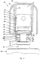
- a closure device 10 for closing a bottle or a container 12 is shown, the opening 14 of which is provided at the upper end of its neck 16 with an outer Crimean rim 18.
- the closure device 10 has a manually operable pump 20, which is preferably made of plastic and the cylinder 22 of which protrudes from the container opening 14, has an invisible, axial passage channel and on the upper end a dispensing head 24 for distributing a fluid contained in the container 12 wearing.
- the pump 20 is covered by a removable protective cap 26.
- This protective cap 26 has a head wall 28, from the underside of which a cylindrical, tubular guide stub 30 projects coaxially to the container axis downwards in the direction of the container 12 and one cylindrical cavity 32 laterally surrounds.
- An inner wall 34 of the guide socket 30 is provided up to its approximately middle height with a cylindrical extension 36, which is offset at the upper end in the form of a stop surface 38 with respect to the inner wall 34 of the guide socket 30.
- a cylindrical coupling ring 40 with a friction seat is inserted, which rests with an upper, inwardly bent end 42 on the stop surface 38 of the extension 36.
- a lower end 44 of the coupling ring 40 protrudes only slightly downward from a lower, open end of the guide socket 30 and engages over an annular adapter 46 with a friction fit, the function of which is explained in more detail below.
- the pump 20 is provided at its end facing the container 12 with an annular flange 48, the diameter of which corresponds approximately to that of the Crimean rim 18.
- An annular sealing disk 50 is arranged under the ring flange 48.
- the adapter 46 is preferably made of plastic and is essentially cylindrical; it is provided at its upper end with an annular inner flange 52 which, according to FIG. 1, rests on the ring flange 48 of the pump 20. At least three snap arms 54 extend from the underside of this annular inner flange 52 at the same circumferential angular intervals parallel to the container axis downward in the direction of the container 12. The snap arms 54 are provided on their inside with a locking groove 56 running at the same height in the circumferential direction. The locking groove 56 serves to receive the annular flange 48 of the pump 20 and the Crimean rim 18 of the container 12.
- the locking groove 56 in the Snap arms 54 are each bounded at the bottom by a latching cam 70, which is designed as a ramp surface 71 which widens downward at the lower end of each snap arm 54.
- This contact surface 71 facilitates the spreading and pushing of the snap arms 54 over the ring flange 48 of the pump 20 in order to form the assembly unit from the protective cap 28, the union ring 40, the adapter 46 and the pump 20.
- the ramp surface 71 also facilitates the assembly of the assembly unit described on the container 12, in which the snap arms 54 extend over the Crimean rim 18 and then engage under it in a blocking or holding manner.
- the coupling ring 40 is axially displaceable on the adapter 46 and, with its lower end, rests on at least one elastic lock 60, which is biased radially outward beyond the cylindrical peripheral surface of the adapter 46.
- the lock 60 consists of at least one, preferably three locking cams 62 which are injection molded between the snap arms 54 on a lower edge of the upper inner flange 52 of the adapter 46 by means of a film joint, not shown.
- the film joint holds the associated locking cam 62 in the radially outwardly elastically biased position, in which each locking cam 62 projects outward beyond the cylindrical peripheral surface of the adapter 46.
- a space 64 Under the lower edge of the inner flange 52 of the adapter 46, a space 64 (FIGS.
- each locking cam 62 radially through the lower end face of the cylindrical coupling ring 40 as a function of the impact force exerted thereon can be bent inwards.
- the coupling ring 40 can then be pushed completely downward on the adapter 46 until it rests on a container shoulder 68 and can be clamped by the locking cams 62.
- the standard pump 20 with the dispensing head 24, the sealing disk 50 and the adapter 46 is mounted on the coupling ring 40.
- the coupling ring 40 equipped in this way is inserted into the guide socket 30 of the protective cap 26 and thus sent to the bottler.
- the bottler puts the pump 20 on the container (FIG. 1).
- the annular flange 48 engages in the locking groove 56 of the adapter 46 after the locking cams 70 at the lower end of the snap arms 54 have been elastically bent radially outward when they strike the annular flange 48.
- the locking cam 62 and the coupling ring 40 are dimensioned such that the coupling ring 40 clamps on the adapter 46 due to the resulting surface pressure and the locking device 10 can be removed for normal use.
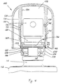
- a guide socket 130 and a coupling ring 140 are modified compared to the first embodiment in FIGS. 1 to 3.
- a lower end of a cylindrical extension 136 in a guide socket 140 of a protective cap 126 is namely delimited by a preferably annular snap bead 172, which on the underside likewise has a run-up surface 174 which widens towards the lower end of the guide socket 130 for easier assembly of the collar ring 140.
- the collar ring 140 is provided at an approximately medium height with an annular bead 176 which, according to FIG. 4, rests on the snap bead 172 of the guide socket 130, so that the collar ring 140 is located between an upper, stepped stop face 138 and the lower, annular snap bead 172 of the extension 136 is axially determined so that separation of the protective cap 126 from the coupling ring 140 is excluded under normal transport conditions.
- the coupling ring 140 is provided at its lower end with an inner circumferential retaining groove 178 which is formed in a bead-like manner by an outer annular bead 179. It serves to engage locking cams 162 of the adapter 146 which form a lock 160, so that the starting or rest position of the closure device 110 on the container 112 is thereby clearly defined, as shown in FIG. 4.
- the closure device 110 In the subsequent assembly phase of the assembly device comprising the closure cap 126, the collar 140 and the adapter 146 with the pump 120, the closure device 110 according to FIG. As a result, the closure device 110 is so firmly connected to the container 112 under compression of a sealing washer 150 that under normal conditions of use the adapter 146 cannot be separated from the Crimean edge 118 of the container 112 and this completely closed position of the closure device 110 is clearly determined.
- Fig. 8 corresponds to the representation of the locking device in Fig. 7, but with the exception of a modified adapter 246, the snap arms 254 of which are provided on the inside with two superimposed locking grooves 256, 258.
- the upper latching groove 256 which is immediately adjacent to an inner flange 252 of the adapter 246, serves to receive an annular flange 248, a pump 220, while the second latching groove 258, arranged below the first latching groove 256, serves to receive a Crimean rim 218 on a neck 216 of a container 212.
- the superimposed locking grooves 256, 258 are separated from one another at such a distance that the sealing of the pump 220 with respect to the container 212 is ensured by sufficient compression of a sealing disk 250.
- the adapter 46; 146 and the protective cap 26; 126 are preferably made of commercially available plastic such as polypropylene or polyethylene as injection molded parts. For high-quality applications, other materials, in particular metals, can also be used for individual components of the closure device 10; 110 can be used.
- the throwing ring 40; 140 is preferably made of aluminum.
- the snap arms 54; 154 have a length such that the sealing disk 50; 150 sealingly on the container 12; 112 rests and a leakage of liquid is prevented.
- the snap arms 54; 154 are outside of the coupling ring 40; 130 against detachment from the Crimean rim 18; 118 secured so that the locking device 10; 110 from container 12; 112 is safely prevented.
- the throwing ring 40; 140 in turn is due to its static friction on the adapter 46; 146 held in this position so that a pushing back of the coupling ring 40; 140 away from container 12; 112 is only possible with considerable effort.
- the friction between the coupling ring 40; 140 and the guide stub 30; 130 in the protective cap 26; 126 considerably lower, so that the protective cap can be removed and replaced without great effort.
- An essential advantage of the second embodiment in FIGS. 4 to 7 over the first embodiment in FIGS. 1 to 3 is that the lock 60; 160 not only prevents the collar ring 140 from moving over the adapter 146, but also prevents the collar ring 140 from slipping off the adapter 146 in the opposite direction. This prevents the individual components of the closure device 110 from being separated from one another by improper handling prior to assembly on the container 112.
Landscapes
- Closures For Containers (AREA)
Applications Claiming Priority (2)
| Application Number | Priority Date | Filing Date | Title |
|---|---|---|---|
| DE4338791A DE4338791C2 (de) | 1993-11-12 | 1993-11-12 | Verschlußvorrichtung für einen Behälter mit einer handbetätigten Pumpe |
| DE4338791 | 1993-11-12 |
Publications (2)
| Publication Number | Publication Date |
|---|---|
| EP0653359A1 true EP0653359A1 (fr) | 1995-05-17 |
| EP0653359B1 EP0653359B1 (fr) | 1997-07-16 |
Family
ID=6502514
Family Applications (1)
| Application Number | Title | Priority Date | Filing Date |
|---|---|---|---|
| EP94117856A Expired - Lifetime EP0653359B1 (fr) | 1993-11-12 | 1994-11-11 | Dispositif de fermeture d'un récipient équipé d'une pompe à main |
Country Status (2)
| Country | Link |
|---|---|
| EP (1) | EP0653359B1 (fr) |
| DE (2) | DE4338791C2 (fr) |
Cited By (16)
| Publication number | Priority date | Publication date | Assignee | Title |
|---|---|---|---|---|
| EP0662351A2 (fr) * | 1993-12-15 | 1995-07-12 | Ing. Erich Pfeiffer GmbH | Distributeur de fluide |
| EP0845100A1 (fr) * | 1995-08-18 | 1998-06-03 | AptarGroup, Inc. | Systemes de montage de pompe pour operation de dosage fixe ou variable |
| FR2760725A1 (fr) * | 1997-03-14 | 1998-09-18 | Teleplastics Ind | Dispositif distributeur pour produits fluides |
| FR2777209A1 (fr) * | 1998-04-14 | 1999-10-15 | Sofab | Dispositif pour le prepositionnement d'une collerette d'habillage sur un bouton-poussoir |
| WO2000049988A3 (fr) * | 1999-02-23 | 2001-09-07 | Boehringer Ingelheim Int | Cartouche de liquide |
| US6685691B1 (en) | 1998-02-27 | 2004-02-03 | Boehringer Ingelheim Gmbh | Container for a medicinal liquid |
| EP1493493A1 (fr) * | 2003-07-04 | 2005-01-05 | Qualipac | Ensemble de distribution de produit |
| FR2859983A1 (fr) * | 2003-09-22 | 2005-03-25 | Valois Sas | Dispositif de fixation et procede de montage pour fixer un organe de distribution sur une ouverture de reservoir |
| US7090093B2 (en) | 1998-11-07 | 2006-08-15 | Boehringer Ingelheim International Gmbh | Pressure compensation device for a two-part container |
| WO2008028199A1 (fr) * | 2006-08-29 | 2008-03-06 | Buzbee (Pty) Ltd | Système de fermeture et procédé associé |
| EP2020264A2 (fr) * | 2007-08-03 | 2009-02-04 | Global One-Pak Limited | Améliorations portant sur des dispositifs à gachette |
| EP2140942A2 (fr) | 2008-06-30 | 2010-01-06 | L'Oreal | Ensemble formant tête de distribution d'un produit propre à être supporté sur un flacon. |
| WO2011154663A1 (fr) * | 2010-06-10 | 2011-12-15 | Rexam Healthcare La Verpilliere | Dispositif de distribution de produit comprenant une pompe et un embout de distribution |
| EP3093074A1 (fr) * | 2015-05-13 | 2016-11-16 | Aptar Radolfzell GmbH | Tête distributrice pour un distributeur pour la sortie d'un liquide et distributeur doté d'une telle tête distributrice et section de fixation pour une telle tête distributrice |
| US9919848B2 (en) | 2012-10-05 | 2018-03-20 | Qualipac | Method for assembling a packaging device |
| US10603451B2 (en) | 2014-11-20 | 2020-03-31 | Boehringer Ingelheim Vetmedica Gmbh | Container for an inhaler |
Families Citing this family (5)
| Publication number | Priority date | Publication date | Assignee | Title |
|---|---|---|---|---|
| DE19533134A1 (de) * | 1995-09-07 | 1997-03-13 | Chapon | Behälterverschluß |
| DE19615422A1 (de) | 1996-04-19 | 1997-11-20 | Boehringer Ingelheim Kg | Zweikammer-Kartusche für treibgasfreie Dosieraerosole |
| US7963955B2 (en) | 1998-02-27 | 2011-06-21 | Boehringer Ingelheim International Gmbh | Container for a medicinal liquid |
| DE10161020A1 (de) * | 2001-12-12 | 2003-07-03 | Kertels Peter | Sprühdose |
| EP2279044A1 (fr) * | 2008-05-19 | 2011-02-02 | MeadWestvaco Corporation | Bague de retenue de pompe et ses procédés d'utilisation |
Citations (4)
| Publication number | Priority date | Publication date | Assignee | Title |
|---|---|---|---|---|
| US3191815A (en) * | 1961-05-08 | 1965-06-29 | Graham Cecil Robert Montgomery | Tops for aerosol containers |
| US4773553A (en) * | 1985-09-12 | 1988-09-27 | Risdon Corporation | Assembly for securing and sealing a dispenser to a flanged container |
| WO1988010221A1 (fr) * | 1987-06-26 | 1988-12-29 | Werding Winfried J | Dispositif pour le stockage et la distribution controlee de produits sous pression |
| US4984702A (en) * | 1990-03-30 | 1991-01-15 | Specialty Packaging Licensing Company, Inc. | Assembly for securing and sealing a dispenser to a flanged container |
Family Cites Families (1)
| Publication number | Priority date | Publication date | Assignee | Title |
|---|---|---|---|---|
| DE7607195U1 (de) * | 1976-03-10 | 1976-07-01 | Karl Klaeger Kg | Fluessigkeitszerstaeuber |
-
1993
- 1993-11-12 DE DE4338791A patent/DE4338791C2/de not_active Expired - Fee Related
-
1994
- 1994-11-11 DE DE59403379T patent/DE59403379D1/de not_active Expired - Lifetime
- 1994-11-11 EP EP94117856A patent/EP0653359B1/fr not_active Expired - Lifetime
Patent Citations (4)
| Publication number | Priority date | Publication date | Assignee | Title |
|---|---|---|---|---|
| US3191815A (en) * | 1961-05-08 | 1965-06-29 | Graham Cecil Robert Montgomery | Tops for aerosol containers |
| US4773553A (en) * | 1985-09-12 | 1988-09-27 | Risdon Corporation | Assembly for securing and sealing a dispenser to a flanged container |
| WO1988010221A1 (fr) * | 1987-06-26 | 1988-12-29 | Werding Winfried J | Dispositif pour le stockage et la distribution controlee de produits sous pression |
| US4984702A (en) * | 1990-03-30 | 1991-01-15 | Specialty Packaging Licensing Company, Inc. | Assembly for securing and sealing a dispenser to a flanged container |
Cited By (34)
| Publication number | Priority date | Publication date | Assignee | Title |
|---|---|---|---|---|
| EP0662351A2 (fr) * | 1993-12-15 | 1995-07-12 | Ing. Erich Pfeiffer GmbH | Distributeur de fluide |
| EP0662351A3 (fr) * | 1993-12-15 | 1995-11-02 | Pfeiffer Erich Gmbh & Co Kg | Distributeur de fluide. |
| US5692650A (en) * | 1993-12-15 | 1997-12-02 | Ing. Erich Pfeiffer Gmbh | Compact dispenser with integral mounting flange |
| EP0845100A1 (fr) * | 1995-08-18 | 1998-06-03 | AptarGroup, Inc. | Systemes de montage de pompe pour operation de dosage fixe ou variable |
| EP0845100A4 (fr) * | 1995-08-18 | 1999-03-17 | Aptargroup Inc | Systemes de montage de pompe pour operation de dosage fixe ou variable |
| FR2760725A1 (fr) * | 1997-03-14 | 1998-09-18 | Teleplastics Ind | Dispositif distributeur pour produits fluides |
| US5941428A (en) * | 1997-03-14 | 1999-08-24 | Teleplastics Industries | Dispensing device for fluid products |
| US6685691B1 (en) | 1998-02-27 | 2004-02-03 | Boehringer Ingelheim Gmbh | Container for a medicinal liquid |
| WO1999052786A1 (fr) * | 1998-04-14 | 1999-10-21 | Rexam Sofab | Dispositif pour le prepositionnement d'une collerette d'habillage sur un bouton-poussoir |
| US6206246B1 (en) * | 1998-04-14 | 2001-03-27 | Rexam Sofab | Device for pre-positioning a covering collar on a pushbutton |
| CN1102903C (zh) * | 1998-04-14 | 2003-03-12 | 雷克斯姆Sofab股份公司 | 遮盖套环在按钮上的预定位装置 |
| FR2777209A1 (fr) * | 1998-04-14 | 1999-10-15 | Sofab | Dispositif pour le prepositionnement d'une collerette d'habillage sur un bouton-poussoir |
| US7090093B2 (en) | 1998-11-07 | 2006-08-15 | Boehringer Ingelheim International Gmbh | Pressure compensation device for a two-part container |
| WO2000049988A3 (fr) * | 1999-02-23 | 2001-09-07 | Boehringer Ingelheim Int | Cartouche de liquide |
| CN1299662C (zh) * | 1999-02-23 | 2007-02-14 | 贝林格尔·英格海姆国际有限公司 | 用于药液的筒 |
| CZ300652B6 (cs) * | 1999-02-23 | 2009-07-08 | Boehringer Ingelheim International Gmbh | Zásobník pro kapalinu a jeho použití |
| EP1493493A1 (fr) * | 2003-07-04 | 2005-01-05 | Qualipac | Ensemble de distribution de produit |
| FR2856994A1 (fr) * | 2003-07-04 | 2005-01-07 | Qualipac Sa | Ensemble de distribution de produit |
| WO2005030607A1 (fr) * | 2003-09-22 | 2005-04-07 | Valois Sas | Dispositif de fixation et procede de montage pour fixer un organe de distribution sur une ouverture de reservoir |
| FR2859983A1 (fr) * | 2003-09-22 | 2005-03-25 | Valois Sas | Dispositif de fixation et procede de montage pour fixer un organe de distribution sur une ouverture de reservoir |
| WO2008028199A1 (fr) * | 2006-08-29 | 2008-03-06 | Buzbee (Pty) Ltd | Système de fermeture et procédé associé |
| EP2020264A2 (fr) * | 2007-08-03 | 2009-02-04 | Global One-Pak Limited | Améliorations portant sur des dispositifs à gachette |
| EP2020264A3 (fr) * | 2007-08-03 | 2009-02-25 | Global One-Pak Limited | Améliorations portant sur des dispositifs à gachette. |
| EP2140942A2 (fr) | 2008-06-30 | 2010-01-06 | L'Oreal | Ensemble formant tête de distribution d'un produit propre à être supporté sur un flacon. |
| FR2961192A1 (fr) * | 2010-06-10 | 2011-12-16 | Rexam Healthcare La Verpillier | Dispositif de distribution de produit comprenant une pompe et un embout de distribution |
| WO2011154663A1 (fr) * | 2010-06-10 | 2011-12-15 | Rexam Healthcare La Verpilliere | Dispositif de distribution de produit comprenant une pompe et un embout de distribution |
| CN103025437A (zh) * | 2010-06-10 | 2013-04-03 | 雷盛医疗拉韦尔皮列尔公司 | 包括泵和分配喷头的产品分配设备 |
| US8863993B2 (en) | 2010-06-10 | 2014-10-21 | Rexam Healthcare La Verpilliere S.A.S. | Product dispensing device comprising a pump and a dispensing end piece |
| CN103025437B (zh) * | 2010-06-10 | 2015-11-25 | 雷盛医疗拉韦尔皮列尔公司 | 包括泵和分配喷头的产品分配设备 |
| US9919848B2 (en) | 2012-10-05 | 2018-03-20 | Qualipac | Method for assembling a packaging device |
| US10603451B2 (en) | 2014-11-20 | 2020-03-31 | Boehringer Ingelheim Vetmedica Gmbh | Container for an inhaler |
| EP3093074A1 (fr) * | 2015-05-13 | 2016-11-16 | Aptar Radolfzell GmbH | Tête distributrice pour un distributeur pour la sortie d'un liquide et distributeur doté d'une telle tête distributrice et section de fixation pour une telle tête distributrice |
| WO2016180633A1 (fr) * | 2015-05-13 | 2016-11-17 | Aptar Radolfzell Gmbh | Tête de distribution d'un distributeur permettant de distribuer un liquide, distributeur muni de ladite tête et section de fixation pour ladite tête de distribution |
| US10363566B2 (en) | 2015-05-13 | 2019-07-30 | Aptar Radolfzell Gmbh | Discharge head for a dispenser for discharging a fluid and dispenser comprising a discharge head of this type and securing section for a discharge head of this type |
Also Published As
| Publication number | Publication date |
|---|---|
| DE59403379D1 (de) | 1997-08-21 |
| EP0653359B1 (fr) | 1997-07-16 |
| DE4338791A1 (de) | 1995-05-18 |
| DE4338791C2 (de) | 1996-05-30 |
Similar Documents
| Publication | Publication Date | Title |
|---|---|---|
| EP0653359B1 (fr) | Dispositif de fermeture d'un récipient équipé d'une pompe à main | |
| DE3146824C2 (de) | "Verschlußdeckel, insbesondere für einen Kraftstofftank" | |
| EP0111798B1 (fr) | Fermeture automatique pour récipient flexible | |
| EP0662351B1 (fr) | Distributeur de fluide | |
| EP1708936B1 (fr) | Adaptateur pour bombes aerosols | |
| WO2003026803A1 (fr) | Dispositif de dosage muni d'un systeme de pompage | |
| EP0048931A1 (fr) | Dispositif verseur pour bouteilles | |
| DE2825259B2 (de) | Manuell betätigbarer Flüssigkeitszerstäuber | |
| WO1989000958A1 (fr) | Fermeture pour recipients avec bec verseur escamotable | |
| DE19739989A1 (de) | Spender für Medien | |
| EP0806344A1 (fr) | Procédé de remplissage par son fond d'un distributeur de colle et distributeur de colle pour la mise en oeuvre du procédé | |
| EP1102719A1 (fr) | Cannelle escamotable | |
| EP1295645B1 (fr) | Dispositif de dosage muni d'une pompe | |
| WO2009132609A1 (fr) | Emballage tubulaire | |
| EP0462390A2 (fr) | Emballage comprenant plusieurs matériaux différents | |
| WO1994029214A1 (fr) | Soupape d'arret en matiere plastique | |
| EP3552989A1 (fr) | Adaptateur pour le distributeur de produit et distributeur de produit | |
| DE60106613T2 (de) | Tube mit grossem halsdurchmesser und starrem ansatzstück | |
| EP0216268B1 (fr) | Récipient en plastique avec une fermeture | |
| DE19705201C1 (de) | Kartusche | |
| EP3552988B1 (fr) | Adaptateur pour le distributeur de produit et distributeur de produit | |
| DE19723947B4 (de) | Auslaufkanüle für einen Flüssigkeitsdispenser und Ventilblock | |
| DE7903111U1 (de) | Verschlussanordnung | |
| DE69919326T2 (de) | Verschnappter Spender mit einem Nachlaufkolben | |
| DE19533134A1 (de) | Behälterverschluß |
Legal Events
| Date | Code | Title | Description |
|---|---|---|---|
| PUAI | Public reference made under article 153(3) epc to a published international application that has entered the european phase |
Free format text: ORIGINAL CODE: 0009012 |
|
| AK | Designated contracting states |
Kind code of ref document: A1 Designated state(s): DE FR GB IT |
|
| 17P | Request for examination filed |
Effective date: 19950630 |
|
| RAP1 | Party data changed (applicant data changed or rights of an application transferred) |
Owner name: APTARGROUP S.A. |
|
| 17Q | First examination report despatched |
Effective date: 19960318 |
|
| GRAG | Despatch of communication of intention to grant |
Free format text: ORIGINAL CODE: EPIDOS AGRA |
|
| GRAH | Despatch of communication of intention to grant a patent |
Free format text: ORIGINAL CODE: EPIDOS IGRA |
|
| GRAH | Despatch of communication of intention to grant a patent |
Free format text: ORIGINAL CODE: EPIDOS IGRA |
|
| GRAA | (expected) grant |
Free format text: ORIGINAL CODE: 0009210 |
|
| AK | Designated contracting states |
Kind code of ref document: B1 Designated state(s): DE FR GB IT |
|
| GBT | Gb: translation of ep patent filed (gb section 77(6)(a)/1977) |
Effective date: 19970716 |
|
| REF | Corresponds to: |
Ref document number: 59403379 Country of ref document: DE Date of ref document: 19970821 |
|
| ET | Fr: translation filed | ||
| PLBE | No opposition filed within time limit |
Free format text: ORIGINAL CODE: 0009261 |
|
| STAA | Information on the status of an ep patent application or granted ep patent |
Free format text: STATUS: NO OPPOSITION FILED WITHIN TIME LIMIT |
|
| 26N | No opposition filed | ||
| REG | Reference to a national code |
Ref country code: GB Ref legal event code: IF02 |
|
| PGFP | Annual fee paid to national office [announced via postgrant information from national office to epo] |
Ref country code: IT Payment date: 20091113 Year of fee payment: 16 Ref country code: GB Payment date: 20091111 Year of fee payment: 16 Ref country code: FR Payment date: 20091123 Year of fee payment: 16 |
|
| PGFP | Annual fee paid to national office [announced via postgrant information from national office to epo] |
Ref country code: DE Payment date: 20091201 Year of fee payment: 16 |
|
| GBPC | Gb: european patent ceased through non-payment of renewal fee |
Effective date: 20101111 |
|
| REG | Reference to a national code |
Ref country code: DE Ref legal event code: R119 Ref document number: 59403379 Country of ref document: DE Effective date: 20110601 Ref country code: DE Ref legal event code: R119 Ref document number: 59403379 Country of ref document: DE Effective date: 20110531 |
|
| REG | Reference to a national code |
Ref country code: FR Ref legal event code: ST Effective date: 20110801 |
|
| PG25 | Lapsed in a contracting state [announced via postgrant information from national office to epo] |
Ref country code: DE Free format text: LAPSE BECAUSE OF NON-PAYMENT OF DUE FEES Effective date: 20110531 |
|
| PG25 | Lapsed in a contracting state [announced via postgrant information from national office to epo] |
Ref country code: FR Free format text: LAPSE BECAUSE OF NON-PAYMENT OF DUE FEES Effective date: 20101130 |
|
| PG25 | Lapsed in a contracting state [announced via postgrant information from national office to epo] |
Ref country code: GB Free format text: LAPSE BECAUSE OF NON-PAYMENT OF DUE FEES Effective date: 20101111 |
|
| PG25 | Lapsed in a contracting state [announced via postgrant information from national office to epo] |
Ref country code: IT Free format text: LAPSE BECAUSE OF NON-PAYMENT OF DUE FEES Effective date: 20101111 |