EP0653293A1 - Reifenform und Verfahren zum Formen eines Reifens - Google Patents
Reifenform und Verfahren zum Formen eines Reifens Download PDFInfo
- Publication number
- EP0653293A1 EP0653293A1 EP94116737A EP94116737A EP0653293A1 EP 0653293 A1 EP0653293 A1 EP 0653293A1 EP 94116737 A EP94116737 A EP 94116737A EP 94116737 A EP94116737 A EP 94116737A EP 0653293 A1 EP0653293 A1 EP 0653293A1
- Authority
- EP
- European Patent Office
- Prior art keywords
- elements
- mold
- molding
- tread
- mold according
- Prior art date
- Legal status (The legal status is an assumption and is not a legal conclusion. Google has not performed a legal analysis and makes no representation as to the accuracy of the status listed.)
- Granted
Links
Images


Classifications
-
- B—PERFORMING OPERATIONS; TRANSPORTING
- B29—WORKING OF PLASTICS; WORKING OF SUBSTANCES IN A PLASTIC STATE IN GENERAL
- B29D—PRODUCING PARTICULAR ARTICLES FROM PLASTICS OR FROM SUBSTANCES IN A PLASTIC STATE
- B29D30/00—Producing pneumatic or solid tyres or parts thereof
- B29D30/06—Pneumatic tyres or parts thereof (e.g. produced by casting, moulding, compression moulding, injection moulding, centrifugal casting)
- B29D30/08—Building tyres
-
- B—PERFORMING OPERATIONS; TRANSPORTING
- B29—WORKING OF PLASTICS; WORKING OF SUBSTANCES IN A PLASTIC STATE IN GENERAL
- B29D—PRODUCING PARTICULAR ARTICLES FROM PLASTICS OR FROM SUBSTANCES IN A PLASTIC STATE
- B29D30/00—Producing pneumatic or solid tyres or parts thereof
- B29D30/06—Pneumatic tyres or parts thereof (e.g. produced by casting, moulding, compression moulding, injection moulding, centrifugal casting)
- B29D30/0601—Vulcanising tyres; Vulcanising presses for tyres
- B29D30/0606—Vulcanising moulds not integral with vulcanising presses
- B29D30/0629—Vulcanising moulds not integral with vulcanising presses with radially movable sectors
- B29D2030/063—Vulcanising moulds not integral with vulcanising presses with radially movable sectors the moulds being split in upper and lower halves
-
- B—PERFORMING OPERATIONS; TRANSPORTING
- B29—WORKING OF PLASTICS; WORKING OF SUBSTANCES IN A PLASTIC STATE IN GENERAL
- B29D—PRODUCING PARTICULAR ARTICLES FROM PLASTICS OR FROM SUBSTANCES IN A PLASTIC STATE
- B29D30/00—Producing pneumatic or solid tyres or parts thereof
- B29D30/06—Pneumatic tyres or parts thereof (e.g. produced by casting, moulding, compression moulding, injection moulding, centrifugal casting)
- B29D30/0601—Vulcanising tyres; Vulcanising presses for tyres
- B29D30/0606—Vulcanising moulds not integral with vulcanising presses
- B29D30/0629—Vulcanising moulds not integral with vulcanising presses with radially movable sectors
- B29D2030/0631—Means for forcing adjacent mould sectors away one from another, e.g. using springs or the like, to create repulsive forces
Definitions
- the present invention relates to the molding of tires, in particular the molding of the tread thereof.
- This induced circumferential movement causes, during molding, flows of rubber oriented towards the circumferential edges of the sectors, that is to say towards the interface between the adjacent sectors.
- This parasitic movement contributes to the appearance of the mold burrs which appear on the tread of a vulcanized tire.
- An object of the invention is to correct these molding defects that constitute the burrs.
- Patent application EP 0 242 840 describes a completely rigid mold comprising a peripheral ring of sectors for molding the tread, two lateral shells for molding the sidewalls (exterior surfaces of the tire) and a rigid core for molding the interior surface of the tire . Since there is no longer any additional shaping, the use of this mold frees the tire designer from a constraint specific to this phase of the molding.
- the completely rigid design of this mold brings many advantages as to the quality of the molded tire because the geometric shapes obtained are of high quality (excellent circularity, in any transverse position). However, the imposed volume molding requires very close tolerances to be observed on the volume of the raw tire blank.
- Another objective of the invention is to be able to retain the advantage of the rigid mold from the point of view of respect and perfect control of the geometric quality of the tires produced with this type of mold, while making the molding operation less sensitive to volume dispersions between the green blanks of the tires to be molded and vulcanized successively in the same mold.
- the mold of the present invention not only achieves these objectives, but also provides a general improvement in the molding and demolding of tires, whether or not a rigid core is used to mold the interior cavity of the tire.
- the invention provides a mold for a tire tread, defining in the molding position a continuous ring comprising a relief composed of successive patterns in the circumferential direction, said patterns ensuring the molding of the tread on the radially outer surface of the tread. bearing, said mold consisting of individually movable elements, in a direction of approximation or distance from the axis of the mold at least on a final molding stroke, the molding of said tread being provided by the radially inner face of each element, said elements also being movable with respect to each other at least while they move along said final stroke, characterized in that each of said elements has a circumferential development corresponding to one of said patterns.
- said elements individually, movable relative to the axis of the mold, and also movable with respect to each other at least while they are moving along said final stroke, have a circumferential dimension sufficiently small that the difference between the components circumferential extremes of the displacement observed at all points of the molding surface of each element is less than 0.04% of the molding perimeter.
- the movement is very substantially radial in all circumferential positions to the molding surface of said elements. This effectively limits parasitic gum flows during molding.
- the tire tread mold defining in the molding position a continuous ring ensuring the molding of the radially outer surface of the tread, said ring consisting of at least 30 elements circumferentially adjacent in the molding position, the radially inner face of each element ensuring the molding of said tread, is characterized in that said elements are movable individually, in a direction of approach or distance from the axis of the mold, at least over a final molding stroke, towards and from the closed position, and in that it comprises means ensuring elastic repulsion in the circumferential direction between each of said elements.
- the elements in question here have a thickness (dimension in the circumferential direction) such that, under service stresses, they do not deform elastically. This means that their elasticity plays no functional role in the present invention. These are not not adjacent sheets, so that their number remains in any case less than 250.
- the invention finds a use for the manufacture of annular treads as they are used in the pre-vulcanized state in certain cold retreading methods.
- the sole of the tread is molded by a membrane or by a rigid shape.
- the invention can also be used for molding a tire.
- the mold also includes means for molding the sides, for example shells as well known.
- the internal cavity of the tire can be molded by a membrane or by a rigid core, the invention being compatible with both methods.
- Figure 1 is a meridian section of a mold according to the invention.
- FIG. 2 is a section perpendicular to the axis of rotation, along II II, in FIG. 1.
- Figures 3 and 4 are views similar to Figure II, showing two different stages of mold opening.
- Figure 5 shows a detail of realization.
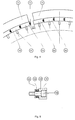
- FIG. 6 illustrates a second variant embodiment of the invention.
- Figure 7 shows the mold of the second variant, in the opening phase.
- Figure 1 there is shown a continuous ring 1 intended to mold the radially outer surface of the tread. This consists of sectors 11, the number of which is generally between five and twenty, on which are mounted elements 10 for molding the sculpture.
- the size of these elements is chosen in the circumferential direction so as to constitute a demouldable pattern.
- the demolding can be carried out in a single demolding direction, causing only slight elastic deformations to the rubber which has just been molded and vulcanized.
- the demouldable pattern can correspond to the tread pitch, a classic concept in tread design for tire treads.
- the demolding direction for which all of the elements 10 are devoid of undercut this is what is shown in FIGS. 2 to 4.
- an element on which there are two adjacent sculpture patterns will still often constitute a demouldable pattern.
- Each item can be obtained in any suitable manner.
- the methods of manufacturing elements by aluminum casting, widely used in the tire industry are suitable.
- the exact shape of these elements, seen from the central axis of the mold, can follow the tread patterns provided by the tire designer (transverse faces not necessarily flat).
- the mold comprises a single element 10 transversely.
- the back of each sector 11 has two frustoconical bearing surfaces 110.
- Each element 10 is threaded over its sector 11 thanks to two lateral grooves 14 provided on each sector 11, and to corresponding studs 15 produced on the rear face of each element 10.
- each sector 11 The radial recoil in the open position of each sector 11 is obtained by releasing the conical hoop 2 to unlock the mold, then by pulling on each sector 11 via the eyelet 3.
- the closure of all the sectors 11 is obtained by moving the hoop 2 axially, which acts on the frustoconical surfaces 110 at the back of each sector 11, and ensures robust locking of the mold. All these movements are classic and there is no need to describe them in detail.
- each element 10 has two housings 12 on either side of the plane of symmetry II-II (see FIG. 1) receiving a member 13 capable of provide a force of repulsion between elements. This is shown in detail in Figure 5.
- the member 13 comprises a flange 131 intended to bear on the bottom of a housing 12. It comprises a head 133, and a stack of belleville washers 132. It is fixed to the bottom of a housing 12 by screwing a bolt 134.
- the housing 12 is hollowed out so that the bolt 134 is not flush, while allowing the head 133 to protrude slightly relative to the transverse face 17, when the member 13 is mounted but not stressed. In this way, the support reactions of said elements 10 on each other, that is to say the support reactions oriented circumferentially, constantly tend to separate the elements 10 from each other.
- the sectors 11 have all retreated by a given stroke, which preferably corresponds to the tread depth. It can be seen that the sectors 11 have separated from each other by an additional distance ⁇ S due to the recoil. Contrary to what would have happened with a sector mold such as those of the state of the art, this distance ⁇ S is not found at the level of the molding surface of the mold.
- the molding elements 10 have all remained equidistant. The difference E which separates them is worth a few tenths of a millimeter. This is made possible by the sliding of most of the elements 10 in the grooves 14 of the sectors (see FIG. 1), under the action of the repulsion members 13 developing a force sufficient to overcome the existing friction forces. Note that these are quite low because, at least during said stroke both in the molding and demolding phase, the radial pressure as the rubber exerted on the mold is weak or zero.
- the mold can continue its opening movement by continuing the retreat of the sectors 11, to reach, or pass through a position such as that represented by FIG. 4. This time, during the movement, all the elements 10 remain immobile by compared to sector 11 on which they are mounted.
- the distance E ′ between edge elements of the adjacent sectors can freely increase, without this having any effect on the demolding operation of the tread.
- the volume of rubber which, during a molding operation, is pinched between the ribs 16a and 16b belonging to different sectors is the same as that pinched between the ribs 16b and 16c belonging to the same sector (not taking into account the variable nature of the step of certain sculptures).
- the theoretical volume available between the ribs 16 of any pair of adjacent elements 10 corresponds to the volume of rubber actually trapped by said ribs 16 during molding.
- the direction of molding and demolding is a direction of approaching or moving away from the axis of the mold. It is not necessarily radial, but can form a non-zero angle to the direction radial if that turns out to be more interesting.
- Some sculptures have non-radiating incisions, such as the strips of M + S 100 type tires sold by MICHELIN.
- the mold seen in radial section, comprises several axially adjacent elements, it is conventionally said that it comprises several groups of elements. One can choose to make it in this way for example to follow a tread pitch which would be different to the left and right of the tire.
- the directions of molding / demolding can be checked separately in each group. It is within each group that all the elements forming part of it will all follow the same direction of approaching or moving away from the axis of the mold.
- each element extends transversely over the entire width of said crown, that is to say from one shoulder to the other of the tire.
- Figures 6 and 7 illustrate another alternative embodiment of the invention, in which the ring ensuring the molding of the sculpture has been divided into two parts G and D. Each of these comprises, transversely, a single element 10G or 10D. This provision is not limitative; There could be several groups of elements on one of the parts or on both parts G and D. In the peripheral direction, like the first variant, each part comprises a large number of 10G or 10D, for example as many as there are sculpture patterns.
- shell 4 both the molding part and the mechanical support on which it rests.
- a crown 5 the role of which is to control the movement of the elements 10G (or 10D) as explained below, is mounted on each of the shells 4. It goes without saying, however, that this arrangement is not limiting, and that these parts could in certain embodiments be movable with respect to each other.
- a centering bead 181 is arranged on the lateral face 18 of the elements 10G of the part G. It cooperates with a corresponding groove made on the lateral face 18 of the elements 10D of the other part.
- the back of each element 10G, 10D, has a contact face 19, axially engaged with a hoop 50.
- the hoop 50 is integral with a few pistons 51, for example at least three distributed equidistantly over the entire circumference of the hoop 50.
- a spring 52 is placed in a housing 53.
- the spring takes support on the one hand on the shell 4, and on the other hand on the piston 51, to tend to push the latter axially inwards until a shoulder 510 provided at the base of the piston 51 comes in abutment against the bottom 530 of the corresponding housing 53.
- a slide 54 for example in dovetail, is fixed on the one hand on the back of each element 10G, 10D, and on the other hand on the radially lower wall of a crown 5.
- This slide 54 constitutes a device ensuring a degree of freedom of sliding between elements 10G or 10D and crown 5. Said sliding takes place along an axis inclined relative to the axis of the mold. The angle of inclination is chosen to be non-wedging, with respect to the opening and closing stresses of the mold, which are oriented parallel to the axis of the mold.
- the only possible movement of the elements 10G (or 10D), in response to the axial bringing together of the shells 4, is a movement of radial advance towards the closed position of the mold. This explains the closing of the mold.
- the movement of all 10G (or 10D) elements is preferably simultaneous and symmetrical.
- the centering cord 181 ensures a perfect symmetry.
- the invention also extends, as already mentioned, to a method of manufacturing a tire using a mold as described above, which may include a rigid core serving as a support for the assembly of the components, then serving as an element molding the interior cavity of the tire during vulcanization.
- the two-part mold of the second embodiment can be used with repulsion members 13 described with the first variant. These replace or assist springs 52.
- the longitudinal grooves are molded by ribs which cannot be circumferentially continuous. These ribs are cut into as many sections as there are elements 10 (or 10G or 10D). It has been experimentally noted that, even when using a rigid core to mold the inside of the tire, if at the time when the ribs of the mold penetrate the raw rubber, the size of the gaps between elements is smaller than 0.3 mm, then there is no 'no mold burr appears.
Landscapes
- Engineering & Computer Science (AREA)
- Mechanical Engineering (AREA)
- Moulds For Moulding Plastics Or The Like (AREA)
- Heating, Cooling, Or Curing Plastics Or The Like In General (AREA)
- Tyre Moulding (AREA)
Applications Claiming Priority (2)
| Application Number | Priority Date | Filing Date | Title |
|---|---|---|---|
| FR9313523 | 1993-11-12 | ||
| FR9313523A FR2712229A1 (fr) | 1993-11-12 | 1993-11-12 | Moule pour pneumatique, et procédé de moulage du pneumatique. |
Publications (2)
| Publication Number | Publication Date |
|---|---|
| EP0653293A1 true EP0653293A1 (de) | 1995-05-17 |
| EP0653293B1 EP0653293B1 (de) | 1999-08-25 |
Family
ID=9452801
Family Applications (1)
| Application Number | Title | Priority Date | Filing Date |
|---|---|---|---|
| EP94116737A Expired - Lifetime EP0653293B1 (de) | 1993-11-12 | 1994-10-24 | Reifenform und Verfahren zum Formen eines Reifens |
Country Status (11)
| Country | Link |
|---|---|
| US (2) | US5639326A (de) |
| EP (1) | EP0653293B1 (de) |
| JP (1) | JP3902248B2 (de) |
| KR (1) | KR100326193B1 (de) |
| CN (1) | CN1043864C (de) |
| BR (1) | BR9404434A (de) |
| CA (1) | CA2135577C (de) |
| DE (1) | DE69420227T2 (de) |
| ES (1) | ES2136150T3 (de) |
| FR (1) | FR2712229A1 (de) |
| RU (1) | RU2130832C1 (de) |
Cited By (3)
| Publication number | Priority date | Publication date | Assignee | Title |
|---|---|---|---|---|
| WO1997014909A1 (fr) * | 1995-10-18 | 1997-04-24 | 3X Engineering | Manchon modulaire pour la protection, la reparation ou la renovation d'une canalisation |
| WO2008065463A1 (en) * | 2006-11-27 | 2008-06-05 | Pirelli Tyre S.P.A. | Apparatus for vulcanization and moulding of vehicles tyres |
| EP1825992A3 (de) * | 2006-02-22 | 2008-08-27 | Toyo Tire Rubber Co., Ltd. | Luftreifen und Verfahren zu seiner Herstellung. |
Families Citing this family (41)
| Publication number | Priority date | Publication date | Assignee | Title |
|---|---|---|---|---|
| FR2712229A1 (fr) * | 1993-11-12 | 1995-05-19 | Sedepro | Moule pour pneumatique, et procédé de moulage du pneumatique. |
| FR2759626A1 (fr) * | 1997-02-19 | 1998-08-21 | Sedepro | Moule pour pneus |
| US6460585B1 (en) | 1998-10-02 | 2002-10-08 | Michelin Recherche Et Techniques, S.A. | Tire with tread compound contacting belt cords |
| EP1371478B1 (de) * | 1999-08-10 | 2010-04-14 | Manufacture Française des Pneumatiques Michelin | Steifer Kern in zwei Teilen, zur Herstellung von Luftreifen |
| US6318985B1 (en) * | 2000-09-15 | 2001-11-20 | Michelin Recherche Et Technique S.A. | Two-piece segmented mold |
| US6826819B1 (en) * | 2000-11-01 | 2004-12-07 | Quality Mold, Inc. | Method for making a ventless tire mold |
| JP2002166424A (ja) * | 2000-11-29 | 2002-06-11 | Bridgestone Corp | 空気入りタイヤの加硫方法およびそれに用いる金型 |
| KR20030003795A (ko) * | 2001-07-02 | 2003-01-14 | 금호산업 주식회사 | 열변형 방지갭을 갖는 타이어 가류용 금형 |
| JP4454306B2 (ja) * | 2001-07-17 | 2010-04-21 | 株式会社ブリヂストン | タイヤの加硫金型 |
| FR2839003A1 (fr) * | 2002-04-29 | 2003-10-31 | Michelin Soc Tech | Moule pour pneus |
| KR100498131B1 (ko) * | 2002-07-09 | 2005-07-01 | 금호타이어 주식회사 | 타이어 블래더 제조용 몰드 |
| WO2004101247A1 (ja) * | 2003-05-13 | 2004-11-25 | Bridgestone Corporation | タイヤ加硫金型および空気入りタイヤ |
| JP4346084B2 (ja) * | 2004-07-06 | 2009-10-14 | 東洋ゴム工業株式会社 | タイヤ成型用金型 |
| US20060125147A1 (en) * | 2004-12-03 | 2006-06-15 | Bachochin Todd A | Segmented tire mold for off-road-vehicle tires |
| JP2007084035A (ja) * | 2005-08-23 | 2007-04-05 | Toyo Tire & Rubber Co Ltd | 空気入りタイヤ及びその製造方法 |
| FR2891489B1 (fr) * | 2005-10-04 | 2007-12-07 | Michelin Soc Tech | Moule pour bande de roulement de pneumatique. |
| JP4702130B2 (ja) * | 2006-03-22 | 2011-06-15 | 横浜ゴム株式会社 | タイヤ成形用二分割金型 |
| JP2007290202A (ja) * | 2006-04-24 | 2007-11-08 | Toyo Tire & Rubber Co Ltd | タイヤ成型用金型及びそれにより成型された空気入りタイヤ |
| JP4780772B2 (ja) * | 2006-06-13 | 2011-09-28 | 東洋ゴム工業株式会社 | タイヤ成型用金型及びそれにより成型された空気入りタイヤ |
| JP4930063B2 (ja) * | 2007-01-11 | 2012-05-09 | 横浜ゴム株式会社 | タイヤ成形用二分割金型 |
| JP4972425B2 (ja) * | 2007-02-13 | 2012-07-11 | 東洋ゴム工業株式会社 | タイヤ加硫成形金型及びタイヤ製造方法 |
| US7540730B1 (en) | 2007-12-20 | 2009-06-02 | The Goodyear Tire & Rubber Company | Tire mold |
| BRPI0822855A2 (pt) * | 2008-06-27 | 2015-06-30 | Michelin Rech Tech | Molde de cura de pneumático |
| BRPI0822857B1 (pt) * | 2008-06-30 | 2019-09-24 | Compagnie Generale Des Etablissements Michelin | Molde de cura de pneumático |
| US8267680B2 (en) * | 2008-08-12 | 2012-09-18 | Michelin Recherche Et Technique S.A. | Mold having mold tooling |
| JP2010052171A (ja) * | 2008-08-26 | 2010-03-11 | Yokohama Rubber Co Ltd:The | タイヤ加硫装置 |
| EP2349700B1 (de) | 2008-10-31 | 2012-09-26 | Pirelli Tyre S.P.A. | Verfahren und vorrichtung zum formen und vulkanisieren von fahrzeugreifen |
| JP5185801B2 (ja) * | 2008-12-25 | 2013-04-17 | 住友ゴム工業株式会社 | タイヤの加硫金型 |
| RU2472618C1 (ru) * | 2008-12-31 | 2013-01-20 | Компани Женераль Дез Этаблиссман Мишлен | Система для замены канавочных пластинок для формования или восстановления шин |
| JP4854766B2 (ja) * | 2009-06-15 | 2012-01-18 | 東洋ゴム工業株式会社 | タイヤ成型用金型 |
| US7963756B2 (en) * | 2009-11-18 | 2011-06-21 | The Goodyear Tire & Rubber Company | Segmented tire mold |
| JP5406265B2 (ja) * | 2011-11-29 | 2014-02-05 | 住友ゴム工業株式会社 | 乗用車用空気入りタイヤの加硫シェーピング方法 |
| FR2984213B1 (fr) * | 2011-12-16 | 2014-01-10 | Michelin Soc Tech | Element moulant comportant des moyens de decoupe pour le moulage et la vulcanisation d'une bande de roulement d'un pneumatique |
| JP5314122B2 (ja) * | 2011-12-28 | 2013-10-16 | 株式会社ブリヂストン | タイヤ成形用金型、タイヤ、及びタイヤの製造方法 |
| FR2998828B1 (fr) * | 2012-12-04 | 2015-05-15 | Michelin & Cie | Moule de vulcanisation pour pneumatique |
| WO2014209367A1 (en) * | 2013-06-28 | 2014-12-31 | Compagnie Generale Des Etablissements Michelin | Tire mold with improved durability |
| FR3008643B1 (fr) * | 2013-07-22 | 2015-12-11 | Michelin & Cie | Moule de vulcanisation pour pneumatique |
| JP6130762B2 (ja) * | 2013-09-19 | 2017-05-17 | 東洋ゴム工業株式会社 | タイヤ成型用金型及びタイヤ成型方法 |
| JP5832505B2 (ja) * | 2013-10-24 | 2015-12-16 | 住友ゴム工業株式会社 | 鋳型作製用ゴム型の芯金および鋳型作製用ゴム型の製造方法 |
| JP6280446B2 (ja) * | 2014-05-27 | 2018-02-14 | 株式会社ブリヂストン | タイヤモールド及びタイヤ加硫装置 |
| CN104708741B (zh) * | 2015-03-25 | 2017-10-03 | 山东豪迈机械科技股份有限公司 | 轮胎模具 |
Citations (4)
| Publication number | Priority date | Publication date | Assignee | Title |
|---|---|---|---|---|
| DE1933816A1 (de) * | 1969-07-03 | 1971-01-14 | Herbert Maschf L | Vulkanisierform fuer Fahrzeugreifen |
| DE2113698A1 (de) * | 1971-03-22 | 1972-09-28 | Uniroyal Ag | Mehrteilige Formmulde |
| EP0451832A2 (de) * | 1990-04-13 | 1991-10-16 | PIRELLI COORDINAMENTO PNEUMATICI S.p.A. | Form zum Vulkanisieren von Reifen und Verfahren zur Herstellung dieser Form |
| EP0514161A1 (de) * | 1991-05-17 | 1992-11-19 | Bridgestone Corporation | Metallische Form zur Vulkanisierung eines Reifens und Verfahren zu deren Herstellung |
Family Cites Families (15)
| Publication number | Priority date | Publication date | Assignee | Title |
|---|---|---|---|---|
| US1197253A (en) * | 1916-03-13 | 1916-09-05 | Arnold Kallmerten | Mold equipment for forming treads on pneumatic tires. |
| US2333588A (en) * | 1940-12-13 | 1943-11-02 | Harry G Schaevitz | Molding apparatus |
| BE471402A (de) * | 1946-08-13 | |||
| BE534904A (de) * | 1954-01-15 | |||
| US2874405A (en) * | 1958-02-13 | 1959-02-24 | Firestone Tire & Rubber Co | Apparatus and method of manufacturing tire |
| GB1245090A (en) * | 1967-11-18 | 1971-09-02 | Dunlop Holdings Ltd | Improvements in or relating to moulding apparatus |
| US3779677A (en) * | 1971-09-27 | 1973-12-18 | Goodyear Tire & Rubber | Segmented tire mold |
| DE2502185C3 (de) * | 1975-01-21 | 1982-02-04 | Continental Gummi-Werke Ag, 3000 Hannover | Vulkanisierform für Fahrzeugluftreifen |
| US4597929A (en) * | 1984-11-23 | 1986-07-01 | The B. F. Goodrich Company | Method for ventless tire molding and tire resulting therefrom |
| FR2597783B1 (fr) * | 1986-04-25 | 1988-08-26 | Michelin & Cie | Moule rigide pour le moulage et la vulcanisation de pneumatiques |
| SU1565720A1 (ru) * | 1988-08-01 | 1990-05-23 | Предприятие П/Я А-3832 | Способ изготовлени армированных упругих оболочек |
| US5120209A (en) * | 1989-12-29 | 1992-06-09 | Macmillan Kenneth T | Apparatus for molding tire treads |
| DE69301059T2 (de) * | 1992-05-13 | 1996-05-15 | Sedepro | Reifenform und Verfahren zum Formen eines Reifens |
| US5405568A (en) * | 1992-10-26 | 1995-04-11 | The Goodyear Tire & Rubber Company | Two-piece segmented tire mold and method of molding |
| FR2712229A1 (fr) * | 1993-11-12 | 1995-05-19 | Sedepro | Moule pour pneumatique, et procédé de moulage du pneumatique. |
-
1993
- 1993-11-12 FR FR9313523A patent/FR2712229A1/fr active Pending
-
1994
- 1994-10-24 EP EP94116737A patent/EP0653293B1/de not_active Expired - Lifetime
- 1994-10-24 DE DE69420227T patent/DE69420227T2/de not_active Expired - Lifetime
- 1994-10-24 ES ES94116737T patent/ES2136150T3/es not_active Expired - Lifetime
- 1994-11-09 US US08/336,785 patent/US5639326A/en not_active Expired - Lifetime
- 1994-11-10 CN CN94118703A patent/CN1043864C/zh not_active Expired - Fee Related
- 1994-11-10 CA CA002135577A patent/CA2135577C/fr not_active Expired - Fee Related
- 1994-11-11 BR BR9404434A patent/BR9404434A/pt not_active IP Right Cessation
- 1994-11-11 KR KR1019940029513A patent/KR100326193B1/ko not_active Expired - Fee Related
- 1994-11-11 RU RU94040141/28A patent/RU2130832C1/ru not_active IP Right Cessation
- 1994-11-14 JP JP30436994A patent/JP3902248B2/ja not_active Expired - Fee Related
-
1997
- 1997-03-20 US US08/822,287 patent/US6017206A/en not_active Expired - Fee Related
Patent Citations (4)
| Publication number | Priority date | Publication date | Assignee | Title |
|---|---|---|---|---|
| DE1933816A1 (de) * | 1969-07-03 | 1971-01-14 | Herbert Maschf L | Vulkanisierform fuer Fahrzeugreifen |
| DE2113698A1 (de) * | 1971-03-22 | 1972-09-28 | Uniroyal Ag | Mehrteilige Formmulde |
| EP0451832A2 (de) * | 1990-04-13 | 1991-10-16 | PIRELLI COORDINAMENTO PNEUMATICI S.p.A. | Form zum Vulkanisieren von Reifen und Verfahren zur Herstellung dieser Form |
| EP0514161A1 (de) * | 1991-05-17 | 1992-11-19 | Bridgestone Corporation | Metallische Form zur Vulkanisierung eines Reifens und Verfahren zu deren Herstellung |
Cited By (7)
| Publication number | Priority date | Publication date | Assignee | Title |
|---|---|---|---|---|
| WO1997014909A1 (fr) * | 1995-10-18 | 1997-04-24 | 3X Engineering | Manchon modulaire pour la protection, la reparation ou la renovation d'une canalisation |
| FR2740199A1 (fr) * | 1995-10-18 | 1997-04-25 | 3X Engineering | Manchon modulaire pour la protection, la reparation ou la renovation d'une canalisation |
| US5988224A (en) * | 1995-10-18 | 1999-11-23 | 3X Engineering | Modular sleeve for protecting, repairing or renovating a pipe |
| CN1074109C (zh) * | 1995-10-18 | 2001-10-31 | 3X工程公司 | 用于保护、修复或更新管道的模块式套筒 |
| EP1825992A3 (de) * | 2006-02-22 | 2008-08-27 | Toyo Tire Rubber Co., Ltd. | Luftreifen und Verfahren zu seiner Herstellung. |
| EP2295230A1 (de) * | 2006-02-22 | 2011-03-16 | Toyo Tire & Rubber Co. Ltd. | Luftreifenherstellungsverfahren |
| WO2008065463A1 (en) * | 2006-11-27 | 2008-06-05 | Pirelli Tyre S.P.A. | Apparatus for vulcanization and moulding of vehicles tyres |
Also Published As
| Publication number | Publication date |
|---|---|
| DE69420227D1 (de) | 1999-09-30 |
| JP3902248B2 (ja) | 2007-04-04 |
| ES2136150T3 (es) | 1999-11-16 |
| CN1106746A (zh) | 1995-08-16 |
| CA2135577C (fr) | 2005-10-04 |
| BR9404434A (pt) | 1995-06-20 |
| DE69420227T2 (de) | 1999-12-16 |
| US6017206A (en) | 2000-01-25 |
| RU94040141A (ru) | 1996-09-20 |
| CN1043864C (zh) | 1999-06-30 |
| KR950013701A (ko) | 1995-06-15 |
| RU2130832C1 (ru) | 1999-05-27 |
| US5639326A (en) | 1997-06-17 |
| JPH07186303A (ja) | 1995-07-25 |
| EP0653293B1 (de) | 1999-08-25 |
| CA2135577A1 (fr) | 1995-05-13 |
| KR100326193B1 (ko) | 2002-09-04 |
| FR2712229A1 (fr) | 1995-05-19 |
Similar Documents
| Publication | Publication Date | Title |
|---|---|---|
| EP0653293B1 (de) | Reifenform und Verfahren zum Formen eines Reifens | |
| EP1232852B1 (de) | Formwerkzeug und Verfahren zum Formen einer Reifenlauffläche | |
| EP0242840B1 (de) | Steife Form zum Formen und Vulkanisieren von Reifen | |
| EP0569909B1 (de) | Reifenform und Verfahren zum Formen eines Reifens | |
| EP2384276B1 (de) | Eine anordnung aus nuten und kerben enthaltende reifenvulkanisierungsform | |
| EP3030406B1 (de) | Reifenform mit einem ringförmigen einsatzstück zum formen eines profils | |
| EP3030407B1 (de) | Form für reifen mit abnehmbarem ringförmigem einsatz | |
| FR2925394A1 (fr) | Pneumatique, moule pour la vulcanisation de ce pneumatique, procede de fabrication de ce moule et matrice de moule | |
| EP1034908B1 (de) | Formwerkzeugelement für Reifenlaufflächen | |
| EP2072204B1 (de) | Form für die Vulkanisierung eines Reifenrohlings | |
| EP0320494B1 (de) | Steife Form zum Formen und Vulkanisieren von Reifen | |
| EP3651963B1 (de) | Verfahren zur herstellung eines luftreifens | |
| EP1000728B1 (de) | Herstellung eines Stützkörpers | |
| EP3024643A1 (de) | Form und verfahren zum vulkanisieren von reifen | |
| EP3898210B1 (de) | Form mit sektoren für reifen, insbesondere reifen für landwirtschaftliche fahrzeuge, und zugehöriges formverfahren | |
| EP1305157B1 (de) | Verfahren zur herstellung einer raupenkette und entformungsvorrichtung | |
| FR2699853A1 (fr) | Moule pour pneumatique, et procédé de moulage du pneumatique. | |
| EP4200127B1 (de) | Vulkanisierform für einen reifen mit mitteln zum schneiden einer gummiformnaht | |
| EP4565414A1 (de) | Vulkanisierform und verfahren zum vulkanisieren eines reifenrohlings |
Legal Events
| Date | Code | Title | Description |
|---|---|---|---|
| PUAI | Public reference made under article 153(3) epc to a published international application that has entered the european phase |
Free format text: ORIGINAL CODE: 0009012 |
|
| AK | Designated contracting states |
Kind code of ref document: A1 Designated state(s): BE CH DE ES FR GB IT LI LU |
|
| 17P | Request for examination filed |
Effective date: 19951117 |
|
| 17Q | First examination report despatched |
Effective date: 19970623 |
|
| GRAG | Despatch of communication of intention to grant |
Free format text: ORIGINAL CODE: EPIDOS AGRA |
|
| GRAG | Despatch of communication of intention to grant |
Free format text: ORIGINAL CODE: EPIDOS AGRA |
|
| GRAH | Despatch of communication of intention to grant a patent |
Free format text: ORIGINAL CODE: EPIDOS IGRA |
|
| GRAH | Despatch of communication of intention to grant a patent |
Free format text: ORIGINAL CODE: EPIDOS IGRA |
|
| GRAH | Despatch of communication of intention to grant a patent |
Free format text: ORIGINAL CODE: EPIDOS IGRA |
|
| GRAA | (expected) grant |
Free format text: ORIGINAL CODE: 0009210 |
|
| AK | Designated contracting states |
Kind code of ref document: B1 Designated state(s): BE CH DE ES FR GB IT LI LU |
|
| RIN1 | Information on inventor provided before grant (corrected) |
Inventor name: SOULALIOUX, ALAIN |
|
| REG | Reference to a national code |
Ref country code: CH Ref legal event code: NV Representative=s name: PAUL GALLEY Ref country code: CH Ref legal event code: EP |
|
| REF | Corresponds to: |
Ref document number: 69420227 Country of ref document: DE Date of ref document: 19990930 |
|
| ITF | It: translation for a ep patent filed | ||
| REG | Reference to a national code |
Ref country code: ES Ref legal event code: FG2A Ref document number: 2136150 Country of ref document: ES Kind code of ref document: T3 |
|
| GBT | Gb: translation of ep patent filed (gb section 77(6)(a)/1977) |
Effective date: 19991101 |
|
| PLBE | No opposition filed within time limit |
Free format text: ORIGINAL CODE: 0009261 |
|
| STAA | Information on the status of an ep patent application or granted ep patent |
Free format text: STATUS: NO OPPOSITION FILED WITHIN TIME LIMIT |
|
| 26N | No opposition filed | ||
| REG | Reference to a national code |
Ref country code: GB Ref legal event code: IF02 |
|
| PGFP | Annual fee paid to national office [announced via postgrant information from national office to epo] |
Ref country code: CH Payment date: 20051014 Year of fee payment: 12 |
|
| PGFP | Annual fee paid to national office [announced via postgrant information from national office to epo] |
Ref country code: ES Payment date: 20051017 Year of fee payment: 12 |
|
| PGFP | Annual fee paid to national office [announced via postgrant information from national office to epo] |
Ref country code: BE Payment date: 20051108 Year of fee payment: 12 |
|
| REG | Reference to a national code |
Ref country code: FR Ref legal event code: TP |
|
| PG25 | Lapsed in a contracting state [announced via postgrant information from national office to epo] |
Ref country code: LI Free format text: LAPSE BECAUSE OF NON-PAYMENT OF DUE FEES Effective date: 20061031 Ref country code: CH Free format text: LAPSE BECAUSE OF NON-PAYMENT OF DUE FEES Effective date: 20061031 |
|
| REG | Reference to a national code |
Ref country code: GB Ref legal event code: 732E |
|
| REG | Reference to a national code |
Ref country code: CH Ref legal event code: PL |
|
| BERE | Be: lapsed |
Owner name: *SEDEPRO Effective date: 20061031 |
|
| REG | Reference to a national code |
Ref country code: ES Ref legal event code: FD2A Effective date: 20061025 |
|
| PG25 | Lapsed in a contracting state [announced via postgrant information from national office to epo] |
Ref country code: ES Free format text: LAPSE BECAUSE OF NON-PAYMENT OF DUE FEES Effective date: 20061025 |
|
| PG25 | Lapsed in a contracting state [announced via postgrant information from national office to epo] |
Ref country code: BE Free format text: LAPSE BECAUSE OF FAILURE TO SUBMIT A TRANSLATION OF THE DESCRIPTION OR TO PAY THE FEE WITHIN THE PRESCRIBED TIME-LIMIT Effective date: 20061031 |
|
| PGFP | Annual fee paid to national office [announced via postgrant information from national office to epo] |
Ref country code: FR Payment date: 20101104 Year of fee payment: 17 |
|
| PGFP | Annual fee paid to national office [announced via postgrant information from national office to epo] |
Ref country code: LU Payment date: 20101025 Year of fee payment: 17 Ref country code: DE Payment date: 20101022 Year of fee payment: 17 |
|
| PGFP | Annual fee paid to national office [announced via postgrant information from national office to epo] |
Ref country code: IT Payment date: 20101026 Year of fee payment: 17 Ref country code: GB Payment date: 20101021 Year of fee payment: 17 |
|
| GBPC | Gb: european patent ceased through non-payment of renewal fee |
Effective date: 20111024 |
|
| REG | Reference to a national code |
Ref country code: FR Ref legal event code: ST Effective date: 20120629 |
|
| PG25 | Lapsed in a contracting state [announced via postgrant information from national office to epo] |
Ref country code: DE Free format text: LAPSE BECAUSE OF NON-PAYMENT OF DUE FEES Effective date: 20120501 |
|
| REG | Reference to a national code |
Ref country code: DE Ref legal event code: R119 Ref document number: 69420227 Country of ref document: DE Effective date: 20120501 |
|
| PG25 | Lapsed in a contracting state [announced via postgrant information from national office to epo] |
Ref country code: IT Free format text: LAPSE BECAUSE OF NON-PAYMENT OF DUE FEES Effective date: 20111024 Ref country code: GB Free format text: LAPSE BECAUSE OF NON-PAYMENT OF DUE FEES Effective date: 20111024 Ref country code: FR Free format text: LAPSE BECAUSE OF NON-PAYMENT OF DUE FEES Effective date: 20111102 |
|
| PG25 | Lapsed in a contracting state [announced via postgrant information from national office to epo] |
Ref country code: LU Free format text: LAPSE BECAUSE OF NON-PAYMENT OF DUE FEES Effective date: 20111024 |