EP0652628A1 - Méthode pour enrouler les stators de moteurs électriques et guide-fil et flasque pour la mise en oeuvre de cette méthode - Google Patents
Méthode pour enrouler les stators de moteurs électriques et guide-fil et flasque pour la mise en oeuvre de cette méthode Download PDFInfo
- Publication number
- EP0652628A1 EP0652628A1 EP94116299A EP94116299A EP0652628A1 EP 0652628 A1 EP0652628 A1 EP 0652628A1 EP 94116299 A EP94116299 A EP 94116299A EP 94116299 A EP94116299 A EP 94116299A EP 0652628 A1 EP0652628 A1 EP 0652628A1
- Authority
- EP
- European Patent Office
- Prior art keywords
- stator
- winding
- wire guide
- wire
- end plate
- Prior art date
- Legal status (The legal status is an assumption and is not a legal conclusion. Google has not performed a legal analysis and makes no representation as to the accuracy of the status listed.)
- Granted
Links
Images


Classifications
-
- H—ELECTRICITY
- H02—GENERATION; CONVERSION OR DISTRIBUTION OF ELECTRIC POWER
- H02K—DYNAMO-ELECTRIC MACHINES
- H02K3/00—Details of windings
- H02K3/46—Fastening of windings on the stator or rotor structure
- H02K3/50—Fastening of winding heads, equalising connectors, or connections thereto
-
- H—ELECTRICITY
- H02—GENERATION; CONVERSION OR DISTRIBUTION OF ELECTRIC POWER
- H02K—DYNAMO-ELECTRIC MACHINES
- H02K15/00—Methods or apparatus specially adapted for manufacturing, assembling, maintaining or repairing of dynamo-electric machines
- H02K15/08—Forming windings by laying conductors into or around core parts
- H02K15/085—Forming windings by laying conductors into or around core parts by laying conductors into slotted stators
-
- Y—GENERAL TAGGING OF NEW TECHNOLOGICAL DEVELOPMENTS; GENERAL TAGGING OF CROSS-SECTIONAL TECHNOLOGIES SPANNING OVER SEVERAL SECTIONS OF THE IPC; TECHNICAL SUBJECTS COVERED BY FORMER USPC CROSS-REFERENCE ART COLLECTIONS [XRACs] AND DIGESTS
- Y10—TECHNICAL SUBJECTS COVERED BY FORMER USPC
- Y10T—TECHNICAL SUBJECTS COVERED BY FORMER US CLASSIFICATION
- Y10T29/00—Metal working
- Y10T29/49—Method of mechanical manufacture
- Y10T29/49002—Electrical device making
- Y10T29/49009—Dynamoelectric machine
Definitions
- the invention is concerned with a method for the mechanical winding of a stator for electric motors and with a wire guide therefor as well as with an end plate for use in this method.
- a stator usually comprises a stator package, which is regularly populated with poles in the circumferential direction, and an associated stator groove is formed between two adjacent poles. Furthermore, such a stator has a central axial through hole, which is generally referred to as a stator hole.
- a winding device for stators and / or armatures of electric motors fixed on a clamping station is known as parts to be wound.
- a winding such as a pole winding
- a winding can be created around a single pole by carrying out the winding wire laying in three controlled axes, the spanned stator as a y-axis being able to perform a rotary movement about its axis, which Wire guide, which is formed there by a winding finger, which is held firmly clamped to a winding needle, for example in a direction perpendicular to the clamping plane, ie a z-axis, and a third movement axis in a direction perpendicular to the zy-plane, ie in an x-direction, for example in that the clamping device with the stator clamped there can be moved in translation on a table arrangement.
- this winding device With the help of this winding device known from DE 37 09 687.7 A1, a pole winding with the x-axis as the laying axis in the form of a layer winding can only be made thanks to the three controlled movement axes reliably create a single pole up to the bottom of the stator slot. After the winding on the assigned pole is then completed, the stator is then switched on and the next pole in the direction of rotation is then wound. Therefore, this winding device allows the winding of a stator only with a winding pattern with winding step 1, ie each pole lying adjacent in the circumferential direction must be provided with a winding separately in individual winding steps.
- stator with a winding pattern with a winding step of greater than 1 hereinafter abbreviated as> 1
- this stator groove is to be skipped would be wrapped and sealed in cross section by the winding wire.
- winding a stator for electric motors with a winding pattern which has a winding step> 1 that is to say that at least one immediately adjacent stator groove is jumped over when winding the stator, or the pole which is immediately adjacent in the circumferential direction is jumped over during winding should.
- DE-B 12 47 457 discloses a device for mechanically winding grooved stator core packages of electrical machines.
- driven winding needles are provided, the angled end part of which is provided with a radial bore forming a needle eye.
- These winding needles are rotatably mounted on a carrier about an axis arranged perpendicular to the winding needle.
- These winding needles with needle eyes engage radially in the stator slots or stator slots to be developed as they pass through the stator bore.
- the winding needles can then move slightly away from each other in the direction away from each other in order to guide the winding wire radially outwards in cooperation with scrapers before the next stator slot is wound.
- a multi-axis movement of the winding needles and a twist over a larger angular range are neither described nor shown there.
- DE-B-12 03 870 describes a wire laying device for a stator winding machine, in which the wire guide members are arranged so that they can be swung radially in and out on a wire laying tube serving as a wire feed.
- These radially retractable and retractable, double-armed wire guide members can only be pivoted about a fixed axis, but are not controllably movable in a controlled manner in at least two degrees of freedom or axes. This results in difficulties when laying the winding wire on the end faces of the stator packet, in particular in the case of a winding step> 1, since the slot cross sections are then partially covered by winding wire that has already been laid and are no longer accessible.
- DE-A-20 31 756 describes a winding and insulating body for stators and / or rotors. However, this winding and insulating body only serves as an end disk and no winding wire receiving space is provided radially outside the end face of the stator package.
- the invention therefore aims to provide a method for the mechanical winding of a stator for electrical machines, which allows the stator to be wound with any winding pattern with a winding step of> 1 in a fully automatic manner. Furthermore, a wire guide and a specially designed end plate are provided.
- a method for mechanically winding a stator package provided with stator slots between pole shoes and a stator bore, which is held on a rotary mount for rotating the stator package about its axis and which is intended for electric motors using a wire guide, that for winding the stator with any winding pattern with a winding step> 1, ie by skipping at least one immediately adjacent stator an end plate made of electrically insulating material is attached to each end of the stator package, which forms a radially and axially outside of the stator slots and runs in the circumferential direction in the circumferential direction, with at least partial clearance of at least one directly adjacent stator slot, and one radial between two adjacent stator slots projecting retaining finger, that the winding wire is laid under tension by means of the wire guide such that the wire guide is moved in at least two controlled axes by means of a holding arm and is moved through the stator bore, the wire guide is about an axis perpendicular to its longitudinal axis for laying
- an end plate made of insulating material is thus attached to each of the two axially opposite end faces of the stator package, as a result of which a winding wire receiving space is formed radially and axially outside the stator slot, so that the winding can be laid, for example, on the stator slot next to the circumference in such a way that the stator groove skipped here is not wound up, but is at least partially kept free, so that it can still be wound in a subsequent winding step.
- a stator for electric motors with any winding pattern can be wound in a fully automatic manner, the winding pattern having a winding step of> 1 and thus at least one immediately adjacent stator groove is skipped during the winding process.
- stator packages can therefore be wound in a universal manner with any winding pattern in accordance with the desired requirements, without having to reclamp the stator package to be developed, so that stators wound with any winding pattern can be wound in an extremely economical manner by the method according to the invention for electric motors.
- the wire guide In order to lay the winding wire radially and axially outside the stator groove in the winding wire receiving spaces formed by the end disks, the wire guide not only performs a translatory movement in the axial direction of the stator package, but also in a controlled manner, preferably provided with a separate drive, a rotary movement about a longitudinal axis vertical axis, so that the wire guide has at least two, separately controlled axes of movement, namely a longitudinal axis of movement in the axial direction of the stator core and a rotational movement axis perpendicular to the longitudinal axis of the wire guide.
- At least half of the cross section of the stator groove is kept free by the winding wire receiving space of the respective end plate. This allows a tightly packed winding with the smallest possible stator size and a correspondingly high line density in the electric motor.
- stator windings are created fully automatically with a winding step of> 1, but at the same time the required stator interconnections required at the contact points, such as pins, terminals or the like, are carried out. These contact points are provided on an outwardly facing side of at least one of the end plates.
- All of these winding processes, including the interconnections at the contact points, can be carried out fully automatically with the aid of the wire guide, which can be moved in at least two axes of movement in conjunction with the rotary movement of the stator package around its own axis, using the respective end plates placed on the stator package.
- the holding arm with the wire guide is not moved axially through the stator bore for laying the winding wire, but only the wire guide is rotated and rotated in a corresponding manner on the predetermined positioned holding arm, and then moved through the stator bore for laying in the stator slots.
- the wire guide is freely rotatable about the axis perpendicular to its longitudinal axis also over angular ranges of 240 ° and beyond, the wire guide can be rotated and moved so that the winding wire can be reliably inserted into the winding wire receiving space on the respective end plate.
- a winding wire receiving space is formed by the end disk, by means of which at least half of the cross section of the stator groove is kept free for later and further winding.
- the winding wire is also laid immediately around contact points for the desired connection of the stator at the start and end of the winding, so that one can achieve fully automatic winding and interconnection of the stator with any and changeable winding steps, in order to ensure economical and effective winding with industrial adaptation to the desired winding pattern even with small motors.
- a wire guide for the mechanical winding of a stator package provided with stator slots and a stator bore for electrical machines or electric motors with any winding pattern with a winding step> 1, i.e. by skipping at least one immediately adjacent stator groove, which is particularly intended for carrying out the method described first
- the wire guide is driven in a controllable manner by means of a holding arm in two or three axes and can be moved through the stator bore, and the wire guide is at one end of the holding arm rotatably supported about an axis perpendicular to its longitudinal axis.
- the winding wire can be laid fully automatically on the stator package with the end disks attached to the two end faces in accordance with the desired winding pattern with a winding step> 1.
- the wire guide designed as a winding finger and the winding needle according to DE 37 09 687 A1 that the wire guide is additionally rotatable or pivotable about an axis perpendicular to its longitudinal axis, so that the winding wire in the winding wire receiving space the end disks can be inserted radially and axially outside the stator groove in a predetermined manner.
- a wire guide for the mechanical winding of a stator groove and a stator package having a stator bore for electrical machines or electric motors is provided, which is particularly suitable for carrying out the method for winding stators for small motors is determined.
- This wire guide is controllably driven by means of a holding arm in two or three axes, rotatably mounted at one end of the holding arm about an axis perpendicular to its longitudinal axis, in such a way that the wire guide is rotatable through angular ranges of 240 ° and more, and the free
- the end of the wire guide is curved in the shape of a hook, so that the winding wire can be reliably inserted into the winding wire receiving space on the end plate and by reaching over and reaching behind the retaining finger on the end plate.
- the rotary drive device for the rotary movement of the wire guide is preferably attached to the holding arm of the wire guide about the axis perpendicular to its longitudinal axis.
- a belt or chain drive or a push rod can be considered as a rotary drive device, for example.
- the wire guide can preferably comprise a blocking cylinder, by means of which the wire guide is locked in its position.
- the design is preferably such that the wire guide is arranged at one end of the holding arm and rotatably supported there, and that the rotary drive device for the wire guide is provided at the end of the holding arm opposite the bearing for the wire guide. In this way, one obtains the additional devices on the holding arm in a balanced manner carrying the same arrangement.
- the end plate specified according to the invention in connection with the method and in a structurally simple and technically advantageous manner, it is achieved that in a winding pattern with a winding step> 1, the adjacent stator groove is partially kept free in cross section and therefore later in a further winding step of the winding sequence can be wound.
- This end plate is produced as a separate part from the actual stator package, and the end plate is then placed on the respective end face of the stator package before winding, for which purpose a positive connection with the stator grooves is preferably produced.
- the winding wire receiving space formed by the end disk then enables the winding wire to be laid along the circumference of the stator packet up to the stator groove to be wound next to the winding pattern radially and axially outside the stator groove in such a way that the stator groove skipped according to the winding pattern is at least 50% calculated in cross section remains free from the base of the stator groove.
- the end disk preferably has an axially extending collar which projects at least partially into the respective stator groove and which is formed in one piece on the end disk.
- This collar serves both as a spacer and for insulation compared to the stator package and the winding laid in the respective stator slot.
- the end plate also fulfills an essential function with regard to the insulation for the winding in the stator slot, which is kept at a distance from the base of the stator slot by means of the collar.
- the end plate preferably has a further essential function, since at least one end plate carries a contact point for connection.
- the end plate thus also serves to connect the installed windings on the stator package, the contacting points being able to be formed, for example, by pins, terminals or the like.
- the collar for positioning and locking the end plate preferably engages in the associated stator groove, as a result of which a positive connection between the end plate and the stator groove on the stator package is obtained.
- the wire guide 1 is on a holding arm 2 by means of a rotary bearing 3 about an axis of rotation designated 4 - As indicated by arrows - rotatably mounted, the axis of rotation 4 is perpendicular to the longitudinal direction or longitudinal axis of the wire guide 1.
- This wire guide 1 can be designed as a wire nozzle, through the interior of which the winding wire to be laid passes (which is not shown in more detail), and which is drawn off from a corresponding supply device under a certain basic tension.
- a rotary drive device For executing the rotary movement of the wire guide 1 about the axis of rotation 4 on the holding arm 2, a rotary drive device, generally designated 5, is provided, which is attached to the holding arm 2 in the vicinity of the end of the holding arm 2 opposite the axis of rotation 4.
- the drive movement is transmitted from the rotary drive device to a pinion 7 such that the wire guide 1 with a corresponding rotary drive movement of the rotary drive 5, a rotary movement or a pivoting movement in the direction indicated by an arrow Executes directions about the axis of rotation 4 in a controlled manner.
- the holding arm 2 together with the wire guide 1 rotatably mounted there is also - as indicated schematically by arrows - movable in at least one, preferably a further direction of movement, which is preferably perpendicular to the first direction of movement, on a suitable winding device, as is the case, for example, in DE 37 09 687.7 A1 is specified in connection with the winding needle provided there and the winding finger, which forms an embodiment of a wire guide in the sense of the invention.
- a suitable winding device as is the case, for example, in DE 37 09 687.7 A1 is specified in connection with the winding needle provided there and the winding finger, which forms an embodiment of a wire guide in the sense of the invention.
- the wire guide 1 is also associated with a hydraulically, pneumatically or electromagnetically, as well as a combination thereof, lock cylinder 8, by means of which the wire guide 1 can be held and locked in the desired position in order to reliably take the wire guide 1 into the desired position, also taking into account the wire managers and the counter-pull.
- lock cylinder 8 by means of which the wire guide 1 can be held and locked in the desired position in order to reliably take the wire guide 1 into the desired position, also taking into account the wire managers and the counter-pull.
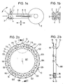
- stator slots arranged at regular intervals in the circumferential direction are shown in connection with the end plate and the stator pack of the stator body, which are denoted in their entirety with 101 to 116 in FIG. 7 to illustrate the winding diagram shown there.
- these stator slots 101 to 116 are open in the radial direction pointing to the stator center axis.
- stator slots 101 to 116 are designated for reasons of clarity in order to explain an example of a winding pattern with a winding step> 1 with regard to the process steps essential according to the invention.
- FIGS. 1-10 A preferred embodiment of an end disk, designated as a whole by 10, is shown and explained as a single part representation with reference to FIGS.
- the end plate 10 is made of an electrically insulating material, preferably a plastic material, as a separate item.
- the dimensions of the end plate 10 are adapted to a stator package 100 to be wound, which has stator slots 101 to 116 and an axially continuous stator bore 117 distributed at regular intervals over the circumference.
- the end plate 10 has a peripheral edge flange 11 covering the end face of the respective stator core 100 and isolating the windings to be created, and a retaining finger 12 axially spaced therefrom between two adjacent stator slots 101 to 116, which is provided in a radially projecting manner and approximately parallel to the peripheral edge flange 11 is. Between the axially spaced circumferential edge flange 11 and the retaining fingers 12 distributed over the circumference, a winding wire receiving space 13 is formed, which with reference to the stator packet 100 is radially and axially outside the stator slots 101 to 116.
- the winding wire receiving space 13 has a depth such that the associated stator slots 101 to 116 are kept at least partially free in cross-section, for example up to about 50%.
- the end plate 10 has contact points 15, for which purpose a receiving opening 16 is provided, for example, in association with the respective retaining finger 12, into which a pin 17 can be inserted as a contact point, which is shown, for example, in FIG. 3b and described in more detail below.
- contact points 15 may also be provided, which may be terminals or the like, for example.
- These contacting points 15 are exposed radially from outside to the end plate 10, i.e. they are provided on the retaining finger 12 on the side facing away from the stator package 100.
- the contacting points 15 are preferably combined only on a single end plate 10.
- the end plate 10 also has, in the region of the peripheral edge flange 11 on the end facing the stator core 100, an insulating collar 18 which, as shown for example in FIG. 6, engages in a form-fitting manner in the associated stator slots 101 to 116.
- This insulating collar 18 partially protrudes into the stator slots 101 to 116 and insulates - as shown for example in FIG. 6 - the windings 40 produced from the stator package 100, and at the same time the insulating collar 18 causes this winding 40 has a predetermined distance from the respective stator slot 101 to 116.
- At least one indexing lug 19 is provided, which is provided on the peripheral edge flange 11 covering the end face of the stator packet 100 and is designed to project radially.
- This indexing lug 19 serves to determine the starting position for controlling the winding processes, and it is separated after the stator or the stator package 100 has been wound. The position of the indexing lug 19 is explained with reference to the end disk 10 in its arrangement attached to the end face of the stator pack 100.
- a wedge wire 30 is then laid under tension by means of the wire guide 1 such that the wire guide 1 is moved in at least two controlled axes by means of a holding arm 2 and is moved through the stator bore 117, the wire guide 1 by one axis 14 perpendicular to its longitudinal axis for laying the winding wire 30 into the winding wire receiving space 13 of the respective end plate 10 is rotated, and the stator package 100 is rotated to the next stator slot 101 to 116 to be wound with the corresponding switching step (not shown in more detail), and the winding wire 30 is guided by the associated retaining finger 12 of the end plate 10.
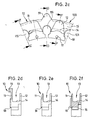
- FIGS. 3a to 6 A preferred embodiment of this procedure divided into individual winding steps will now be explained specifically with reference to FIGS. 3a to 6.
- a finished, wound stator groove is then illustrated as a single view in an axial sectional view as an example in FIG. 6.
- step a) see FIGS. 3a and 3b - the winding wire 30 is placed on a contact point 15 (pin 17) of the end plate 10 and wound around it, for example.
- the contact point 15 lies on the side of the end disk 10 facing away from the stator pack 100.
- the wire guide 1 for example, as indicated by an arrow in FIG. 3a, performs a rotary movement about its longitudinal axis around the winding wire 30 with a plurality of wraps around the pin 17, which is a start pin, for example.
- the winding wire 30 is then guided past the retaining finger 12 of the end plate 10 after it has been placed on the contact point 15 or wound on the pin 17 in a step b) on the side facing away from the contact point 15, as can be seen from the left-hand illustration in FIG. 3b can be seen.
- the winding wire 30 is inserted into the winding wire receiving space 13 formed by the end disk 10 and, as can be seen in the left-hand illustration in FIG. 3, is guided to the first groove 101 to be wound.
- the winding wire 30 is then pulled through the stator groove 101, for example, up to the axially opposite end of the stator packet 100 with the end disk 10 applied and slightly beyond.
- the wire guide 1 with the holding arm 2 leads one Movement in the axial direction through the stator bore 117, and the wire guide 1 is moved axially.
- the wire guide 1 is finally rotated or pivoted about its axis 4 perpendicular to the longitudinal axis in step c).
- the winding wire 30 is inserted into the winding wire receiving space 13 formed by the end disk 10 on the opposite side of the stator packet 100.
- a step d as is shown in the right-hand illustration in FIG.
- stator 100 with the attached end disks 10 is rotated about its axis and the winding wire 30 goes here on the side of the retaining finger 12 facing the stator pack 100 End disk 10 over to the next stator groove to be wound according to the winding pattern, which is formed by the stator groove 115 in the example shown.
- This winding process represents a winding step> 1, since the stator groove 116 which is directly adjacent to the groove 101 in the circumferential direction is skipped during the winding, and the stator groove 115 is thus wound next.
- the winding wire receiving space 13 formed by the end plate 10 is located radially and axially outside the stator slots 101 to 116 and the bottom 14 of the winding wire receiving space 13 is as far out as possible, so that the associated stator slot 101 to 116 is kept as free as possible is, for example, the stator groove 116, which was skipped in the above-described method steps a) to d) during the winding process.
- step e) the wire guide 1 is guided back through the stator bore 117 by executing an axial movement of the holding arm 2, as a result of which the winding wire 30 is laid, for example, in the stator slot 115.
- the wire guide 1 is moved to the axially opposite end of the stator pack 100 and the attached end plate 10 and slightly beyond.
- the wire guide 1 is rotated or pivoted about its axis 4 perpendicular to the longitudinal axis under appropriate control by the rotary drive device 5, and the winding wire 30 is placed and laid in the winding wire receiving space 13 formed by the end disk 10 while passing the sides of the retaining finger 12 facing the stator pack 100.
- step g steps c) to f) are repeated until the desired winding pattern on the stator packet 100 is completed with a winding step of> 1.
- step h) similar to step a), the end of the winding wire 30 is applied and attached to an end contact point (for example an end pin 17) by moving the wire guide 1 in a corresponding manner.
- an end contact point for example an end pin 17
- a stator is completely wound with the desired winding pattern and it is also connected.
- the indexing nose 19 of the end plate 10 is then separated and the wound stator 100 can be used for its intended purpose for an electrical machine or an electric motor.
- FIG. 6 shows a single wound stator groove of the stator packet 100 for clarification.
- the winding made from the winding wire 30 according to the method according to the invention is designated 40 overall.
- the winding 40 is laid radially and axially outside the stator slot 101 to 116 in the winding wire receiving spaces 13 formed in the end disks 10, and the insulating collars 18 on the end disks 10 serve as spacer elements to the associated stator slot 101 to 116 Winding 40 is sufficiently insulated from the stator packs 100 and, thanks to the insulating collar 18 of the end plates 10, there is therefore a space with a distance d.
- winding wire 30 of the winding 40 is laid radially and axially outside in the winding wire receiving spaces 13 of the end disks 10, the next neighboring for winding stator slots 101 to 116, these are kept free in cross-section and can then be wound largely unhindered in a later winding step in the winding sequence, so that with the method according to the invention any winding pattern with a winding step of> 1 can be created fully automatically without difficulty.
- FIG. 7 schematically shows a winding scheme for a two-pole stator.
- the winding sequence includes the creation of the differently marked windings I to IV, with one winding step per winding of> 1 being provided in this winding pattern.
- the stator slots 101 and 115, the stator slots 102 and 114, the stator slots 103 and 113 and the stator slots 104 and 112 are wound by the method according to the invention (see solid line for the first winding I).
- the second winding II which is entered with a broken line and provided with two points, is created by the method according to the invention in such a way that the stator slots 104 and 112, the stator slots 105 and 111, the stator slots 106 and 110 and the stator slots 107 and 109 be wound.
- the third winding III which is entered with a dotted line in FIG. 7, then comprises the winding of the stator slots 108 and 116, the stator slots 107 and 101, the stator slots 106 and 102 and 105 and 103.
- the fourth winding IV then to be created which is entered with a dotted line in FIG. 7, includes the winding of the stator slots 103 and 105, the stator slots 102 and 106, the stator slots 101 and 107 and the stator slots 116 and 108.
- the windings respectively produced on the stator package 100 are then in each case fixed to the assigned start pins S and end pins E, whereby, for example, the winding of the wound stator is carried out in the method according to the invention.
- These end pins and start pins are designated in FIG. 7 with S1 and E1, S2 and E2, S3 and E3 and with S4 and E4. These are assigned to the windings I to IV specified in the winding sequence.
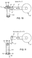
- this wire guide 1 ′ which is designed in this way, is rotated on the holding arm 2 ′ about the axis of rotation in a corresponding manner and is moved in a predetermined manner with the aid of the holding arm, so that, for example, the winding wire start around a contact point, such as a pin 17, can be wrapped.
- FIG. 9 thus illustrates the method steps a ') and b') described above in connection with FIG. 3 a).
- the winding wire 30 is placed on a contact point 15 and it is guided past the retaining finger 12 of the end plate 10 on a side facing away from the contact point 15.
- the contact point has a pin 17.
- FIG. 10 serves to illustrate the method step c '), in which the winding tasks are carried out in accordance with the above procedure with step c).
- step c ' the winding wire 30 is then inserted directly into the winding wire receiving space 13, which is formed in connection with the attached end plate 10, with the aid of the wire guide 1' which is curved in the manner of a hook. without this, the holding arm 2 'is moved axially through the stator bore 117.
- steps e ') and f') are then carried out in the winding process with the aid of the wire guide 1 ', in that the wire guide 1' then, after the stator package has been switched on, to a stator slot which is to be wound next to the winding pattern and after the winding wire has been laid in The same is then rotated in a corresponding manner, as shown in FIG. 11, in such a way that the winding wire 30 is inserted into the corresponding winding wire receiving space, which is delimited in connection with the end plate 10, with the aid of the wire guide 1 'and its hook-shaped free end.
- These method steps which are essential according to the alternative method and differ from the procedure explained above, are then carried out repeatedly until the winding of the stator package 100 is completed.
- the invention is not limited to the above in connection with the method, the end plate 10 and the Wire guide 1; 1 'explained details, but of course numerous changes and modifications are possible both with regard to the details and the overall combination.
- the end disks 10 can be designed and constructed differently than shown. The same applies to the wire guide 1, 1 'and its details.
- end plates 10 are provided on the end face of the stator package 100, which form a winding wire receiving space 13 such that the Winding wire 30 can be laid axially and radially outside of the stator slots 101 to 116 from the respective slot ends to the beginning of the slot in such a way that the intermediate stator slot 101 to 116 which is skipped here is not covered, but is largely kept free, and therefore in the subsequent winding sequence as specified of the corresponding winding pattern can be wound.
- the winding takes place fully automatically, preferably using an appropriately programmable or learning-programmable control, the wire guide 1, 1 'not only being able to carry out a translational linear movement, but also an axis of rotation 4, 4' perpendicular to its longitudinal axis being rotatable and pivotable about which To be able to insert winding wire 30 into the winding wire receiving spaces 13 of the end plates 10.
- the motion sequences can of course be superimposed, which also applies to the individually structured process steps a) to h) or a ') to h'), so that thanks to a multi-axis movement movement and the resulting overall superimposed movements of the stator package 100 and the wire guide 1, 1 'freely selectable and any winding pattern with a winding step of> 1 can create.
Applications Claiming Priority (2)
| Application Number | Priority Date | Filing Date | Title |
|---|---|---|---|
| DE4337870 | 1993-11-05 | ||
| DE4337870A DE4337870C2 (de) | 1993-11-05 | 1993-11-05 | Verfahren zum maschinellen Bewickeln eines Stators für Elektromotoren und Drahtführer sowie Endscheibe hierfür |
Publications (2)
| Publication Number | Publication Date |
|---|---|
| EP0652628A1 true EP0652628A1 (fr) | 1995-05-10 |
| EP0652628B1 EP0652628B1 (fr) | 1996-03-20 |
Family
ID=6501935
Family Applications (1)
| Application Number | Title | Priority Date | Filing Date |
|---|---|---|---|
| EP94116299A Expired - Lifetime EP0652628B1 (fr) | 1993-11-05 | 1994-10-14 | Méthode pour enrouler les stators de moteurs électriques et guide-fil et flasque pour la mise en oeuvre de cette méthode |
Country Status (4)
| Country | Link |
|---|---|
| US (3) | US5596796A (fr) |
| EP (1) | EP0652628B1 (fr) |
| DE (2) | DE4337870C2 (fr) |
| ES (1) | ES2084523T3 (fr) |
Cited By (2)
| Publication number | Priority date | Publication date | Assignee | Title |
|---|---|---|---|---|
| EP1990899A1 (fr) * | 2007-05-11 | 2008-11-12 | ATS Wickel- und Montagetechnik AG | Dispositif destiné à l'enroulement de stators de moteurs électriques |
| EP3460964A1 (fr) * | 2017-09-22 | 2019-03-27 | Aumann Espelkamp GmbH | Dispositif d'enroulement et procédé d'enroulement |
Families Citing this family (25)
| Publication number | Priority date | Publication date | Assignee | Title |
|---|---|---|---|---|
| DE4337870C2 (de) * | 1993-11-05 | 1995-08-24 | Ruoss Spezialmaschinen | Verfahren zum maschinellen Bewickeln eines Stators für Elektromotoren und Drahtführer sowie Endscheibe hierfür |
| US6271608B1 (en) * | 1996-03-29 | 2001-08-07 | Newage International Limited | Alternating current machines |
| JPH10271774A (ja) * | 1997-03-28 | 1998-10-09 | Nittoku Eng Co Ltd | 巻線機 |
| US5895004A (en) * | 1997-04-07 | 1999-04-20 | Labinal Components & Systems, Inc. | Coil winding apparatus for large diameter magnetic rings |
| US6003805A (en) * | 1997-05-13 | 1999-12-21 | Globe Products Inc. | Adjustable stator winding head and method for adjusting the same |
| EP0878898A1 (fr) * | 1997-05-16 | 1998-11-18 | Zihlmann Wickeltechnik AG | Procédé et dispositif d'enroulement de bobines dans les rainures axiales de corps d'appareils électriques, ayant une symétrie de rotation |
| US6325318B1 (en) * | 1999-01-13 | 2001-12-04 | Axis Usa, Inc. | Wire guide for winding dynamo-electric machine stators without shrouds |
| US6533208B1 (en) * | 1999-08-12 | 2003-03-18 | Axis U.S.A., Inc. | Winding cores with stratification motion |
| JP3380885B2 (ja) * | 2000-05-25 | 2003-02-24 | 株式会社林工業所 | モータ固定子の巻線方法及び巻線装置 |
| EP1467466A3 (fr) * | 2003-04-11 | 2007-04-11 | ATS Wickel- und Montagetechnik AG | Stator d'une machine électrique ansi que la méthode et le dispositif pour enrouler ce stator |
| DE102004037639B4 (de) | 2004-08-02 | 2023-04-20 | Sew-Eurodrive Gmbh & Co Kg | Mehrphasenentwicklung, Elektromotor und Fertigungsverfahren |
| EP1722464B1 (fr) * | 2005-05-11 | 2019-05-08 | Brose Fahrzeugteile GmbH & Co. KG, Würzburg | Méthode pour bobiner un stator de moteur électrique et stator de moteur électrique |
| DE202005011333U1 (de) * | 2005-07-15 | 2006-11-23 | Brose Fahrzeugteile Gmbh & Co. Kommanditgesellschaft, Coburg | Verstellsystem eines Kraftfahrzeugs |
| DE102005037373B4 (de) * | 2005-08-08 | 2011-05-05 | Siemens Ag | Elektrische Maschine mit einer stirnseitigen Umlenkung von elektrischen Leitern |
| US20080016676A1 (en) * | 2006-07-18 | 2008-01-24 | Jones Robert M | Automatic winder for an inside brushless stator |
| ATE435515T1 (de) * | 2006-12-22 | 2009-07-15 | Ats Wickel Und Montagetechnik | Vorrichtung zum wickeln von statoren von elektromotoren |
| DE102013216210B4 (de) | 2013-08-15 | 2022-04-28 | Volkswagen Aktiengesellschaft | Wickelkörper für einen Stator eines Elektromotors |
| DE102014006406B4 (de) * | 2014-04-25 | 2018-01-04 | Audi Ag | Vorrichtung und Verfahren zum Bewickeln eines Wicklungsträgers |
| DE102015007836A1 (de) * | 2015-03-13 | 2016-09-15 | Audi Ag | Verfahren zum Wickeln einer Spule |
| DE102015216322A1 (de) * | 2015-08-26 | 2017-03-02 | Continental Automotive Gmbh | Plastikkappen zur elektrischen Isolierung |
| ITUA20162025A1 (it) * | 2016-03-25 | 2017-09-25 | Marsilli S P A | Macchina per l'esecuzione di avvolgimenti di filo su nuclei disposti sulla superficie laterale interna di statori cilindrici per motori elettrici. |
| US10447108B2 (en) * | 2017-02-22 | 2019-10-15 | Gm Global Technology Operations Llc. | Distributed connection ring assembly for stator assembly |
| CN106672696B (zh) * | 2017-03-14 | 2019-10-11 | 中原工学院 | 一种驻极丝线自动缠绕设备及其缠绕方法 |
| DE102017208674A1 (de) | 2017-05-23 | 2018-11-29 | Robert Bosch Gmbh | Verfahren zum Wickeln eines Sternrückschlussstators für einen elektronisch kommutierten Motor |
| DE102020119497A1 (de) | 2020-07-23 | 2022-01-27 | Kuka Deutschland Gmbh | Verfahren und Vorrichtung zum Anbringen von Wicklungen |
Citations (5)
| Publication number | Priority date | Publication date | Assignee | Title |
|---|---|---|---|---|
| FR1153754A (fr) * | 1955-06-16 | 1958-03-21 | Bendix Aviat Corp | Perfectionnements aux machines à bobiner pour l'obtention de résistances symétriques dans des enroulements polyphasés |
| DE1203870B (de) * | 1962-02-03 | 1965-10-28 | Frieseke & Hoepfner Gmbh | Drahtverlegungsvorrichtung fuer eine Statorwickelmaschine |
| DE1247457B (de) * | 1961-07-21 | 1967-08-17 | Balzer & Droell K G | Vorrichtung zum mechanischen Bewickeln von genuteten Staenderblechpaketen elektrischer Maschinen |
| CH444950A (de) * | 1964-09-28 | 1967-10-15 | Elektromat Veb | Ständerwickelmaschine zum Einlegen der Spulen in die Nuten der Ständer elektrischer Maschinen |
| CH493137A (de) * | 1969-07-16 | 1970-06-30 | Rotel Ag | Hilfskörper zum Wickeln von Statoren und Rotoren |
Family Cites Families (21)
| Publication number | Priority date | Publication date | Assignee | Title |
|---|---|---|---|---|
| CA595336A (en) * | 1954-04-26 | 1960-03-29 | Bendix Aviation Corporation | Stator coil winding device |
| DE1011505B (de) * | 1954-04-26 | 1957-07-04 | Bendix Aviat Corp | Formteil zum Wickeln von Statorspulen |
| US2810848A (en) * | 1954-06-01 | 1957-10-22 | Bendix Aviat Corp | Method and means of making stator coil end turns |
| CA587168A (fr) * | 1955-04-01 | 1959-11-17 | I. Roberts George | Dispositif de formation de bobine |
| DE1033320B (de) * | 1955-05-06 | 1958-07-03 | Bendix Aviat Corp | Formteil zum Wickeln von Statorspulen |
| US3055601A (en) * | 1955-06-16 | 1962-09-25 | Bendix Corp | Coil forming means to provide symmetrical resistance in a multi-coil electrical device |
| CA624916A (en) * | 1955-06-16 | 1961-08-01 | I. Roberts George | Multiphase device having symmetrical resistance |
| US3227382A (en) * | 1958-01-15 | 1966-01-04 | Link Engineering Company | Coil winding machine |
| US3253792A (en) * | 1963-04-19 | 1966-05-31 | Fort Wayne Tool & Die Inc | Stator winding machine and tooling therefor |
| DE3150970A1 (de) * | 1981-12-23 | 1983-06-30 | Robert Bosch Gmbh, 7000 Stuttgart | Anschlussvorrichtung fuer die wicklung einer elektrischen maschine |
| US4498636A (en) * | 1982-02-25 | 1985-02-12 | Kollmorgen Technologies Corporation | Stator winding apparatus and method |
| JPS58195452A (ja) * | 1982-05-08 | 1983-11-14 | Matsushita Electric Ind Co Ltd | 電動機固定子の巻線方法 |
| CH661158A5 (de) * | 1982-08-07 | 1987-06-30 | Hitachi Koki Kk | Vorrichtung zum wickeln von drahtspulen fuer elektrische maschinen. |
| JPS59178947A (ja) * | 1983-03-29 | 1984-10-11 | Matsushita Electric Ind Co Ltd | 電動機固定子の巻線方法 |
| DE3709687C2 (de) * | 1987-03-25 | 1995-04-06 | Ruoss Spezialmaschinen | Wickelvorrichtung für die universelle Bewicklung unterschiedlicher Teile |
| DE3929331C1 (de) * | 1989-09-04 | 1990-12-13 | Buehler Gmbh Nachf Geb | Verfahren zur Herstellung und zum Bewickeln von für Elektro-Motore mit Innenläufer bestimmten Statorblechpaketen |
| US5025997A (en) * | 1989-12-04 | 1991-06-25 | Industrial Technology Research Institute | Multi-phase synchronous automatic winding method and apparatus for motor stators |
| US5370324A (en) * | 1990-09-25 | 1994-12-06 | Globe Products Inc. | Stator winding method and apparatus |
| JPH04344137A (ja) * | 1991-05-20 | 1992-11-30 | Sanyo Electric Co Ltd | 電動機の固定子及び固定子の製造方法 |
| GB9310500D0 (en) * | 1993-05-21 | 1993-07-07 | De Beers Ind Diamond | Cutting tool |
| DE4337870C2 (de) * | 1993-11-05 | 1995-08-24 | Ruoss Spezialmaschinen | Verfahren zum maschinellen Bewickeln eines Stators für Elektromotoren und Drahtführer sowie Endscheibe hierfür |
-
1993
- 1993-11-05 DE DE4337870A patent/DE4337870C2/de not_active Expired - Fee Related
-
1994
- 1994-10-14 DE DE59400167T patent/DE59400167D1/de not_active Expired - Lifetime
- 1994-10-14 ES ES94116299T patent/ES2084523T3/es not_active Expired - Lifetime
- 1994-10-14 EP EP94116299A patent/EP0652628B1/fr not_active Expired - Lifetime
- 1994-11-07 US US08/335,081 patent/US5596796A/en not_active Expired - Lifetime
-
1996
- 1996-09-24 US US08/719,402 patent/US5810278A/en not_active Expired - Lifetime
-
1998
- 1998-03-23 US US09/046,044 patent/US5906331A/en not_active Expired - Lifetime
Patent Citations (5)
| Publication number | Priority date | Publication date | Assignee | Title |
|---|---|---|---|---|
| FR1153754A (fr) * | 1955-06-16 | 1958-03-21 | Bendix Aviat Corp | Perfectionnements aux machines à bobiner pour l'obtention de résistances symétriques dans des enroulements polyphasés |
| DE1247457B (de) * | 1961-07-21 | 1967-08-17 | Balzer & Droell K G | Vorrichtung zum mechanischen Bewickeln von genuteten Staenderblechpaketen elektrischer Maschinen |
| DE1203870B (de) * | 1962-02-03 | 1965-10-28 | Frieseke & Hoepfner Gmbh | Drahtverlegungsvorrichtung fuer eine Statorwickelmaschine |
| CH444950A (de) * | 1964-09-28 | 1967-10-15 | Elektromat Veb | Ständerwickelmaschine zum Einlegen der Spulen in die Nuten der Ständer elektrischer Maschinen |
| CH493137A (de) * | 1969-07-16 | 1970-06-30 | Rotel Ag | Hilfskörper zum Wickeln von Statoren und Rotoren |
Cited By (2)
| Publication number | Priority date | Publication date | Assignee | Title |
|---|---|---|---|---|
| EP1990899A1 (fr) * | 2007-05-11 | 2008-11-12 | ATS Wickel- und Montagetechnik AG | Dispositif destiné à l'enroulement de stators de moteurs électriques |
| EP3460964A1 (fr) * | 2017-09-22 | 2019-03-27 | Aumann Espelkamp GmbH | Dispositif d'enroulement et procédé d'enroulement |
Also Published As
| Publication number | Publication date |
|---|---|
| EP0652628B1 (fr) | 1996-03-20 |
| US5810278A (en) | 1998-09-22 |
| ES2084523T3 (es) | 1996-05-01 |
| DE4337870C2 (de) | 1995-08-24 |
| DE4337870A1 (de) | 1995-05-11 |
| DE59400167D1 (de) | 1996-04-25 |
| US5596796A (en) | 1997-01-28 |
| US5906331A (en) | 1999-05-25 |
Similar Documents
| Publication | Publication Date | Title |
|---|---|---|
| EP0652628B1 (fr) | Méthode pour enrouler les stators de moteurs électriques et guide-fil et flasque pour la mise en oeuvre de cette méthode | |
| EP1722464B1 (fr) | Méthode pour bobiner un stator de moteur électrique et stator de moteur électrique | |
| EP2477315B1 (fr) | Système d'enroulement d'aiguille pour supports d'enroulement devant être enroulés, procédé d'enroulement de supports d'enroulement à enroulement réparti, stator intérieur, rotor extérieur et support d'enroulement pour moteurs électriques à enroulement réparti | |
| EP0922289B1 (fr) | Procede et dispositif pour la production d'un agencement de bobines | |
| DE2502112A1 (de) | Verfahren und vorrichtung zum verlegen von adern | |
| EP0968563B1 (fr) | Procede et dispositif de production d'enroulements ondules pour machines electriques | |
| DE60309539T2 (de) | Mehrzahl von Leiterabschnitten Statorwicklungen für elektrische Drehmaschinen, und Verfahren zu seiner Herstellung | |
| EP1905146A1 (fr) | Procede pour produire un enroulement d'une machine electrique | |
| DE112017001564T5 (de) | Wickelvorrichtung und Wickelverfahren | |
| CH665728A5 (de) | Verfahren zum andrillen von drahtenden an kontaktstifte. | |
| DE2954664C2 (fr) | ||
| DE112020000082T5 (de) | Spulenwicklungsvorrichtung, Spulenwicklungsverfahren und Spulenherstellungsverfahren, das sie verwendet | |
| DE3027457A1 (de) | Vorrichtung und verfahren zum einfuehren zuvor gewickelter spulen in die nuten eines stators einer drehbaren elektrischen maschine | |
| DE60311955T2 (de) | Apparat und Verfahren zur Herstellung einer Mehrleiter-Wicklung | |
| DE19817304B4 (de) | Verfahren und Vorrichtung zum Herstellen von Wellenwicklungen für elektrische Maschinen | |
| EP1633035A2 (fr) | Procédé d'enroulement d'un bobinage électrique pour une machine électrique | |
| DE3630024A1 (de) | Verfahren und vorrichtung zum bewickeln von elektrischen wickelkoerpern mit mehreren spulenwickelachsen | |
| EP3167540B1 (fr) | Procédé de fabrication d'une machine électrique comportant des bobines formées et machine électrique et outil de fabrication | |
| DE2117048A1 (de) | Wellenwicklung für elektrische Maschinen | |
| DE19757068C1 (de) | Verfahren und Vorrichtung zum Herstellen einer Formspule für eine Erregerwicklung | |
| DE102020131719A1 (de) | Klemmvorrichtung und -verfahren | |
| DE2302192C3 (de) | Verfahren und Vorrichtung zum Wickeln von Statorspulen für elektrische Maschinen | |
| DE3709687A1 (de) | Wickelvorrichtung | |
| DE102008018971A1 (de) | Verfahren und Vorrichtung zur Herstellung einer elektrischen Wicklung | |
| DE102021101678B3 (de) | Verfahren zum Bewickeln einer sich in einer Längsrichtung erstreckenden Zahnkette |
Legal Events
| Date | Code | Title | Description |
|---|---|---|---|
| PUAI | Public reference made under article 153(3) epc to a published international application that has entered the european phase |
Free format text: ORIGINAL CODE: 0009012 |
|
| AK | Designated contracting states |
Kind code of ref document: A1 Designated state(s): CH DE ES FR GB IT LI PT |
|
| 17P | Request for examination filed |
Effective date: 19950503 |
|
| 17Q | First examination report despatched |
Effective date: 19950711 |
|
| GRAH | Despatch of communication of intention to grant a patent |
Free format text: ORIGINAL CODE: EPIDOS IGRA |
|
| GRAA | (expected) grant |
Free format text: ORIGINAL CODE: 0009210 |
|
| AK | Designated contracting states |
Kind code of ref document: B1 Designated state(s): CH DE ES FR GB IT LI PT |
|
| ITF | It: translation for a ep patent filed |
Owner name: MARCHI & MITTLER S.R.L. |
|
| REG | Reference to a national code |
Ref country code: CH Ref legal event code: NV Representative=s name: PATENTANWAELTE GEORG ROEMPLER UND ALDO ROEMPLER |
|
| REF | Corresponds to: |
Ref document number: 59400167 Country of ref document: DE Date of ref document: 19960425 |
|
| REG | Reference to a national code |
Ref country code: ES Ref legal event code: FG2A Ref document number: 2084523 Country of ref document: ES Kind code of ref document: T3 |
|
| GBT | Gb: translation of ep patent filed (gb section 77(6)(a)/1977) |
Effective date: 19960426 |
|
| ET | Fr: translation filed | ||
| SC4A | Pt: translation is available |
Free format text: 960417 AVAILABILITY OF NATIONAL TRANSLATION |
|
| PLBE | No opposition filed within time limit |
Free format text: ORIGINAL CODE: 0009261 |
|
| STAA | Information on the status of an ep patent application or granted ep patent |
Free format text: STATUS: NO OPPOSITION FILED WITHIN TIME LIMIT |
|
| 26N | No opposition filed | ||
| REG | Reference to a national code |
Ref country code: GB Ref legal event code: IF02 |
|
| REG | Reference to a national code |
Ref country code: CH Ref legal event code: PCAR Free format text: ALDO ROEMPLER PATENTANWALT;BRENDENWEG 11 POSTFACH 154;9424 RHEINECK (CH) |
|
| PGFP | Annual fee paid to national office [announced via postgrant information from national office to epo] |
Ref country code: DE Payment date: 20101021 Year of fee payment: 17 |
|
| PGFP | Annual fee paid to national office [announced via postgrant information from national office to epo] |
Ref country code: IT Payment date: 20101030 Year of fee payment: 17 Ref country code: GB Payment date: 20101021 Year of fee payment: 17 |
|
| PGFP | Annual fee paid to national office [announced via postgrant information from national office to epo] |
Ref country code: CH Payment date: 20111025 Year of fee payment: 18 Ref country code: PT Payment date: 20111004 Year of fee payment: 18 Ref country code: FR Payment date: 20111103 Year of fee payment: 18 Ref country code: ES Payment date: 20111024 Year of fee payment: 18 |
|
| REG | Reference to a national code |
Ref country code: PT Ref legal event code: MM4A Free format text: LAPSE DUE TO NON-PAYMENT OF FEES Effective date: 20130415 |
|
| REG | Reference to a national code |
Ref country code: CH Ref legal event code: PL |
|
| GBPC | Gb: european patent ceased through non-payment of renewal fee |
Effective date: 20121014 |
|
| REG | Reference to a national code |
Ref country code: FR Ref legal event code: ST Effective date: 20130628 |
|
| PG25 | Lapsed in a contracting state [announced via postgrant information from national office to epo] |
Ref country code: CH Free format text: LAPSE BECAUSE OF NON-PAYMENT OF DUE FEES Effective date: 20121031 Ref country code: DE Free format text: LAPSE BECAUSE OF NON-PAYMENT OF DUE FEES Effective date: 20130501 Ref country code: GB Free format text: LAPSE BECAUSE OF NON-PAYMENT OF DUE FEES Effective date: 20121014 Ref country code: LI Free format text: LAPSE BECAUSE OF NON-PAYMENT OF DUE FEES Effective date: 20121031 |
|
| REG | Reference to a national code |
Ref country code: DE Ref legal event code: R119 Ref document number: 59400167 Country of ref document: DE Effective date: 20130501 |
|
| PG25 | Lapsed in a contracting state [announced via postgrant information from national office to epo] |
Ref country code: FR Free format text: LAPSE BECAUSE OF NON-PAYMENT OF DUE FEES Effective date: 20121031 Ref country code: PT Free format text: LAPSE BECAUSE OF NON-PAYMENT OF DUE FEES Effective date: 20130415 Ref country code: IT Free format text: LAPSE BECAUSE OF NON-PAYMENT OF DUE FEES Effective date: 20121014 |
|
| REG | Reference to a national code |
Ref country code: ES Ref legal event code: FD2A Effective date: 20140115 |
|
| PG25 | Lapsed in a contracting state [announced via postgrant information from national office to epo] |
Ref country code: ES Free format text: LAPSE BECAUSE OF NON-PAYMENT OF DUE FEES Effective date: 20121015 |