EP0652377B1 - Moyens de régulation de soupapes pour des dispositifs hydrauliques de manoeuvre - Google Patents
Moyens de régulation de soupapes pour des dispositifs hydrauliques de manoeuvre Download PDFInfo
- Publication number
- EP0652377B1 EP0652377B1 EP94307123A EP94307123A EP0652377B1 EP 0652377 B1 EP0652377 B1 EP 0652377B1 EP 94307123 A EP94307123 A EP 94307123A EP 94307123 A EP94307123 A EP 94307123A EP 0652377 B1 EP0652377 B1 EP 0652377B1
- Authority
- EP
- European Patent Office
- Prior art keywords
- valve
- switching valve
- pilot
- pilot oil
- control
- Prior art date
- Legal status (The legal status is an assumption and is not a legal conclusion. Google has not performed a legal analysis and makes no representation as to the accuracy of the status listed.)
- Expired - Lifetime
Links
Images


Classifications
-
- E—FIXED CONSTRUCTIONS
- E02—HYDRAULIC ENGINEERING; FOUNDATIONS; SOIL SHIFTING
- E02F—DREDGING; SOIL-SHIFTING
- E02F9/00—Component parts of dredgers or soil-shifting machines, not restricted to one of the kinds covered by groups E02F3/00 - E02F7/00
- E02F9/20—Drives; Control devices
- E02F9/22—Hydraulic or pneumatic drives
- E02F9/2278—Hydraulic circuits
- E02F9/2285—Pilot-operated systems
-
- E—FIXED CONSTRUCTIONS
- E02—HYDRAULIC ENGINEERING; FOUNDATIONS; SOIL SHIFTING
- E02F—DREDGING; SOIL-SHIFTING
- E02F3/00—Dredgers; Soil-shifting machines
- E02F3/04—Dredgers; Soil-shifting machines mechanically-driven
- E02F3/28—Dredgers; Soil-shifting machines mechanically-driven with digging tools mounted on a dipper- or bucket-arm, i.e. there is either one arm or a pair of arms, e.g. dippers, buckets
- E02F3/36—Component parts
- E02F3/42—Drives for dippers, buckets, dipper-arms or bucket-arms
- E02F3/43—Control of dipper or bucket position; Control of sequence of drive operations
- E02F3/435—Control of dipper or bucket position; Control of sequence of drive operations for dipper-arms, backhoes or the like
- E02F3/437—Control of dipper or bucket position; Control of sequence of drive operations for dipper-arms, backhoes or the like providing automatic sequences of movements, e.g. linear excavation, keeping dipper angle constant
-
- E—FIXED CONSTRUCTIONS
- E02—HYDRAULIC ENGINEERING; FOUNDATIONS; SOIL SHIFTING
- E02F—DREDGING; SOIL-SHIFTING
- E02F3/00—Dredgers; Soil-shifting machines
- E02F3/04—Dredgers; Soil-shifting machines mechanically-driven
- E02F3/28—Dredgers; Soil-shifting machines mechanically-driven with digging tools mounted on a dipper- or bucket-arm, i.e. there is either one arm or a pair of arms, e.g. dippers, buckets
- E02F3/36—Component parts
- E02F3/42—Drives for dippers, buckets, dipper-arms or bucket-arms
- E02F3/43—Control of dipper or bucket position; Control of sequence of drive operations
- E02F3/435—Control of dipper or bucket position; Control of sequence of drive operations for dipper-arms, backhoes or the like
- E02F3/439—Automatic repositioning of the implement, e.g. automatic dumping, auto-return
Definitions
- the present invention relates to a valve control unit for hydraulic actuators used in machinery such as construction equipment.
- Some valve control units for hydraulic actuators are equipped with an automatic-control switching valve for automatically controlling a main valve and a manual-control switching valve for manually controlling the main valve. Both the automatic control switching valve and the manual control switching valve are connected to a hydraulic pilot oil circuit between a pilot pump and a pilot chamber of the main valve. The pilot oil circuit supplies pressurized pilot oil to the pilot chamber in order to automatically and manually control the main valve that drives the hydraulic actuator. While manually controlling the manual-control switching valve in such a valve control unit, however, an operator may not detect that the hydraulic actuator has reached its a predetermined limit state position (i.e., the hydraulic actuator is either fully extended or fully retracted), but because manual control continues, pressurized oil continues to be supplied to the main valve.
- a predetermined limit state position i.e., the hydraulic actuator is either fully extended or fully retracted
- a limit state switching valve can be provided to switch a pilot hydraulic passage closed in order to stop the flow of pressurized oil to the main valve the hydraulic actuator reaches the predetermined limit state.
- the hydraulic circuit of a conventional valve control unit includes a main pump 51, a pilot pump 52, a power source (driving mechanism) 53 that drives the main pump 51 and the pilot pump 52, an actuator (hydraulic cylinder) 54, a main valve 55 disposed in a main hydraulic circuit between the main pump 51 and the actuator 54, a stroke sensor 56 for detecting the length that the actuator 54 extends or retracts, a control section 57, an automatic-control switching valve 58, 59 that is switched according to the automation control command of the control section 57, a manual-control switching valve 60, an oil reservoir 61, and a manual-operation detection sensor 62 for detecting when the manual-control switching valve 60 is operating.
- limit state switching valves 63, 64 are disposed in the pilot oil passage between the manual-switching valve 60 and each pilot chamber 55a, 55b of the main valve 55 in order to stop pressurized oil from being further supplied to the main valve by switching the main valve according to a control command once the actuator 54 is detected to have reached predetermined limit state during manual operation.
- the conventional valve control unit is equipped with the limit state switching valves 63, 64 in the hydraulic circuit between the manual-control switching valve 60 and each pilot chamber 55a, 55b of the main valve 55. Accordingly, the conventional valve control unit requires one pair of limit state switching valves for each actuator, which increases component and construction costs and lowers reliability.
- An object of the present invention is to provide a valve control unit for hydraulic actuators that eliminates at least one of the pair of limit state switching valves as required in the prior art system.
- a valve control unit for an hydraulic actuator comprising:
- one of said plural manual-control switching valves is provided in a valve assembly, and said valve assembly includes a pump port connected to the pilot pump side which corresponds to each manual-control switching valve.
- the device is still constituted such that one of the limit state switching valves which is provided to switch the pilot oil passage in order to stop pressurized oil from being further supplied to the main valve when the actuator has come to the predetermined limit state, may match one of the actuators.
- reference numeral 1 denotes a conventional hydraulic shovel, having a tracked carriage 2, a rotating section 3 mounted to the tracked carriage 2, and an operating section 4 that is connected to the front of the rotating section 3.
- the operating section 4 includes a boom 8, an arm 6, and a bucket 7, each of which can be operated by extending or retracting a hydraulic cylinder 11, such as an arm cylinder 8, a boom cylinder 9, and a bucket cylinder 10.
- the various hydraulic cylinders 11 correspond to the hydraulic actuators of the present invention.
- a valve control unit 90 is shown.
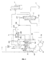
- the valve control unit 90 includes a main hydraulic circuit that extends from a main pump 13 to an extension side and a retraction side of each hydraulic cylinder 11 and is opened or closed according to a switching operation of a main valve 12.
- Each main valve 12 is a 6-port 3-position switching valve of the spring-forced neutral return type.
- the main valve switching operation is carried out with pressurized pilot oil that is fed by manually controlling a manual operating device, such as an operating lever 14, and by automatic control according to a command transmitted from a pilot control device 15, as described below in greater detail.
- a main pump 13 and a pilot pump 16 are powered by a power source 26. Oil in a main hydraulic circuit is pumped by the main pump 13 to the main valve 12 and then returns to a main reservoir 27.
- the feeding of the pressurized pilot oil can be described, for example, with reference to the main valve 12 of the boom cylinder 9.
- a first switching valve 18, a second switching valve 19, and a third switching valve 20, all of which are proportional control valves are disposed between between each pilot chamber 12E, 12R (of the extension and retraction sides of the main valve 12) and the pilot pump 16 and an oil reservoir 17.
- the first switching valve 18 (corresponding to a manual-control switching valve) comprises a first extension switching valve 18E on the extension side and a first retraction switching valve 18R on the retraction side and operates to selectively switch the first extension switching valve 18E or the first retraction switching valve 18R according to a control input from the manual operating device 14.
- the second switching valve 19 (corresponding to a automatic-control switching valve) and third switching valve 20 (corresponding to a limit state manual switching valve) are electromagnetic valves of the 2-position switching type that are switched according to a control command from a pilot control device 15.
- the second switching valve 19 comprises a second extension switching valve 19E on the extension side and a second retraction switching valve 19R on the retraction side (when addressing both 19E, 19R, they will be referred to as second switching valve 19).
- pilot oil flows through the third switching valve 20, a second retraction switching valve 19R of the second switching valve 19, and through a second extension switching valve 19E of the second switching valve 19 to the first switching valve 18.
- Each port of the switching valves 18, 19, and 20 is connected as shown.
- Ports 20a, 20b, and 20c of the third switching valve are connected to the pilot pump 16, the oil reservoir 17, and a port 19Ra of the second retraction switching valve 19R, respectively.
- Ports 19Rb, 19Rc, and 19Rd of the second retraction switching valve 19R are connected to the oil reservoir 17, a port 19Ea of the second extension switching valve 19E, and a pilot chamber 12R, respectively.
- Ports 19Eb and 19Ed of the second extension switching valve 19E are connected to the oil reservoir 17 and a pilot chamber 12E, respectively.
- a port 19Ec extends to the first switching valve 18 and branches to connect a port 18Ea of the first extension switching valve 18E with a port 18Ra of the first retraction switching valve 18R.
- ports 18Eb and 18Ec of the first extension switching valve 18E are connected to the oil reservoir 17 and the pilot chamber 12E, respectively.
- the hydraulic passage that leads from the port 18Ec to the pilot chamber 12E is connected by a shuttle valve 21e with the oil passage that leads from the port 19Ed of the second extension switching valve 19E to the pilot chamber 12E.
- Ports 18Rb and 18Rc of the first retraction switching valve 18R are connected to the oil reservoir 17 and the pilot chamber 12R, respectively.
- the hydraulic passage that leads from the port 18Rc to the pilot chamber 12R is connected by a shuttle valve 21R with the oil passage that leads from the port 19Rd of the second retraction switching valve 19R to the pilot chamber 12R.
- the first switching valve 18 functions to selectively switch the first extension switching valve 18E or the first retraction switching valve 18R according to the side toward which the operating lever 14 has been moved. If, for example, the operating lever 14 is moved toward the right (i.e., to the position shown in Fig. 2A or 3), the valve passage that leads from the second extension switching valve 19E to the pilot chamber 12R opens and the valve passage that leads from the pilot chamber 12R to the oil reservoir 17 closes.
- Pressure switches 22E and 22R are provided in each hydraulic passage between the first extension switching valve 18E and the shuttle valve 21E, and the first retracting switching valve 18R and the shuttle valve 21R, respectively.
- the pressure switches 22E and 22R send a detection signal to the pilot control device 15 when the pressure of the pilot oil exceeds a predetermined valve.
- the pilot control device 15 determines if the hydraulic actuator is being manually controlled when the detection signal is received from the pressure switches 22E and 22R. If the hydraulic actuator is being manually controlled, the manual control signals override the automatic control signals.
- the second switching valve 19 is switched in accordance with the commands transmitted from the pilot control device 15.
- the command from the pilot control device 15 changes from manual control to automatic control, however, only the third switching valve 20 (corresponding to a manual extension or retraction of the boom cylinder 9).
- the pilot control device 15 transmits a command to the second extension switching valve 19E, it changes from a first position in which a valve passage connecting the second retraction switching valve 19R and the first switching valve 18E was open and a valve passage leading from the pilot chamber 12E to the oil reservoir 17 was open to a second position in which a valve passage between the second retraction switching valve 19R and the pilot chamber 12E becomes open and a valve passage connecting the first switching valve 18 and the oil reservoir 17 becomes open.
- the pilot control device 15 transmits a command to the second retraction switching valve 19R, it changes from a first position in which a valve passage connecting the third switching valve 20 and the second extension switching valve 19E was open and a valve passage connecting the pilot chamber 12R to the oil reservoir 17 was open to a second position in which a valve passage between the third switching valve 20 and the pilot chamber 12R becomes open and a valve passage connecting the second extension switching valve 19E and the oil reservoir 17 becomes open.
- the third switching valve 20 changes from a first position in which a valve passage connecting the pilot pump 16 and the second retraction switching valve 19R was open and a valve passage between the second retraction switching valve 19R and the oil reservoir 17 was open to a second position in which a valve passage connecting the pilot pump 16 and the second retraction switching valve 19R becomes open and a valve passage between the second retraction switching valve 19R and oil reservoir 17 becomes open.
- a stroke sensor 23 is mounted on the boom cylinder 9 for sending a detection signal to the pilot control device 15.
- the pilot control device 15 transmits a limit-stop command to the third switching valve 20 when the detected value transmitted from the stroke sensor 23 reaches a predetermined extension-retraction limit value for the boom cylinder 9. This extension-retraction limit value may be varied by the operator.
- the third switching valve 20 is switched from the first position to the second position.
- the pilot control device 15 transmits a limit stop releasing command to the third switching valve 20 directing it to return from the second position to the first position when the detection signal has not been transmitted from the pressure switch 22E or 22R.
- Hydraulic passages which lead from the pilot pump 16 to a third switching valve for an arm cylinder 24 and from the pilot pump 16 to a third switching valve for a bucket cylinder 25, are positioned so as to branch midway along a hydraulic passage between the pilot pump 16 and the third switching valve for the boom cylinder 20, respectively.
- the control of the boom cylinder 9 can be described.
- the first retraction switching valve 18R is switched and the valve passage between the second retraction switching valve 19R and the pilot chamber 12R opens, thereby allowing pressurized pilot oil to flow from the pilot pump 16 to the pilot chamber 12R through the third switching valve 20, the second switching valve 19, and the first retraction switching valve 18R (i.e., as depicted by the heavy solid line).
- the main valve 12 is then switched to the retraction side (not shown) and the detection signal from the pressure switch 22R is transmitted to the pilot control device 15, which determines that the boom cylinder is being manually controlled.
- a limit-stop command is transmitted from the pilot control device 15 to the third switching valve 20.
- the third switching valve 20 changes from the first position to the second position, thereby closing the hydraulic passage between the pilot pump 16 and the first retraction switching valve 18R and stopping the flow of pressurized pilot oil to the pilot chamber 12R (i.e., as depicted by the heavy solid line).
- the main valve 12 returns to a neutral position (not shown).
- the pilot control device 15 If a detection signal is not transmitted from the pressure switch 22R to the pilot control device 15 because the main valve has returned to the neutral position, the pilot control device 15 transmits a limit-stop releasing command to the third switching valve 20, the third switching valve 20 then returns from the second position to the first position.
- the pilot control device 15 determines that the hydraulic cylinders are in the automatic control state so long as the automatic control starter switch 28 has been turned on. If a command to, e.g., extend the boom 9, is transmitted to the second extension switching valve 19E by automatic control, the second extension switching valve 19E open the valve passage between the second retraction switching valve 19R and the pilot chamber 12E (Fig. 4). Pressurized pilot oil flows from the pilot pump 16 to the pilot chamber 12E through the third switching valve 20 and the second switching valve 19, (i.e., as depicted by the heavy solid line) and the main valve 12 switches to the extension side (not shown).
- Configurations for both instantaneous switching and gradual switching may be used to operate the third switching valve 20. While instantaneous switching permits the main valve to be stopped instantaneously, gradual switching is used to gradually control the flow at the deceleration starting position slightly before the extension retraction limit position, that is to say, it takes a certain time for the main valve 12 to return to the stopping position and correspondingly the boom cylinder 9 gradually decelerates and then stops.
- detecting the deceleration starting position is made by detecting whether the detected value from the stroke sensor 23 has reached the predetermined detected value before the extension retraction limit value (it is more convenient to have the structure that said value can be freely set). Then deceleration begins at the deceleration starting position to stop the boom cylinder 9 smoothly and without impact at either the extension or retraction limit position. It should be noted that when the detection of said deceleration starting position is made in accordance with the detected value from such a sensor acting as a stroke sensor which detects the value continuously changed, a discretionary predetermined detected value different from the extension and retraction limit value can be set as a deceleration starting position value. Where there is a transfer switch which is switched by detecting a certain point, the deceleration starting position detecting switch can be provided for detection of the position in addition to the extension retraction limit position detecting switch.
- the embodiment according to the present invention may selectively use automatic control and manual control, and when the hydraulic cylinder 11 reaches the extension-retraction operating limit state in manual control, the third switching valve 20 is automatically switched, and pressurized oil feeding to the hydraulic cylinder 11 is stopped. This prevents a possible malfunction in which pressurized oil would continue to flow after the hydraulic cylinder 11 reached its limit state.
- the third switching valve 20 (which is switched when the hydraulic cylinder is in the operation limit state) is disposed in a pilot oil passage that connects the pilot oil pump 16 and the first automatic control switching valve 18, one of the third switching valves 20E, 20R can be used to control one hydraulic cylinder 11.
- each first switching valve of a number of hydraulic cylinders is incorporated into a single valve assembly.
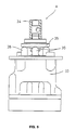
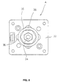
- Figs. 5-10 depict a valve assembly A into which the switching valves 18E, 18R of the boom cylinder 9 and the first switching valves 30E, 30R are incorporated.
- the valve assembly A includes two pump ports P1, P2, a tank port T, and four output ports 01, 02, 03, and 04.
- one end of the pump port P1 is connected to a hydraulic passage leading to the second extension switching valve 19E of the boom cylinder (this hydraulic passage further leads to the pilot pump 16 through the second retraction switching valve 19R and the third switching valve 20).
- the other end of the pump port P1 branches and connects to each port 18Ea, 18Ra of the first switching valve of the boom cylinder.
- One end of the pump port P2 is connected to a hydraulic passage leading to the second extension switching valve 31E of the bucket cylinder (this hydraulic passage further leads to the pilot pump 16 through the second retraction switching valve 31R and the third switching valve 25).
- the other end of pump port P2 branches and connects to each port 30Ea, 30Ra of the first switching valves 30E, 30R of the bucket cylinder.
- One end of the tank port T is connected to a hydraulic passage leading to the oil reservoir 17.
- the other end of tank port T branches into a total of four passages, each of which connect to a port 18Eb, 18Rb, 3OEb, and 3ORb.
- Each end of output ports 01, 03 is connected by a hydraulic passage to the pilot chambers 12E, 12R, respectively, of the main valve for the boom cylinder 32E, 32R, respectively of the main valve for the bucket cylinder.
- Each other end of each output port 01, 02, 03, 04 is connected to each port 18Ec, 18Rc, 3OEc, and 3ORc, respectively, of the first switching valves 18E, 18R, 30E, and 3OR.
- the lower portion of the operating lever 34 is supported on the top of a case 33 of the valve assembly A such that the operating lever 34 can be freely moved in the forward/backward and right/left directions.
- An operating plate 35 is supported beneath the operating lever 34 by the upper ends of four push rods 36. The four push rods operate to switch the first switching valve 18 by pushing up against the lower surface of the operating plate 35 under the action of springs (not shown).
- any of the first switching valves 18E, 18R of the boom cylinder 9 and the first switching valves 30E, 3OR of the bucket cylinder 10, may be switched by moving the single operating lever 34.
- the pump ports P1 and P2 are connected with to the side of the pilot pump 16 are provided in this system, it is possible to dispose the third switching valves 20 and 25 which block the pilot oil feeding in the cylinder extension-retraction limit state, and thereby the present invention can be easily embodied
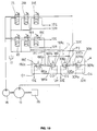
- FIG. 11 An alternative embodiment is shown in Fig. 11.
- the shuttle valves 21E, 21R of the present invention are always opened by means of a hydraulic passage between the first switching valve 18 and the pilot chambers 12E, 12R.
- the shuttle valves may be configured such that they are normally closed under the force of a resilient element 40 (e.g., a spring).
- a resilient element 40 e.g., a spring
- the hydraulic passages between the second switching valve 19 and the pilot chambers 12E, 12R open only when pressurized pilot oil flows from the second switching valves 19E, 19R to the pilot chambers 12E, 12R.
- pressure switches 22E, 22R detect whether the system is being operated manually.
- manual operation can be detected, e.g., by a limit switch of the contact type.
- the switching operation of the third switching valve 20 is possibly continued while the manual operating device 14 is continually moved even once the actuator has reached the extension or retraction limit. Such malfunction may be prevented by means of an adjustment.
- the third switching valve 20 can be controlled such that it does not return to the first position when the extension or retraction limit is detected.
- the valve 20 is switched from the first position to the second position, and the operation is detected with the limit switch of the limit side.
- the third switching valve 20 is controlled such that it automatically returns to the first position when the operation has been detected with the limit switch of the limit side, otherwise the operation is detected with the limit switch of the non-limit side or an automatic switch operates.
- the valve control unit is designed such that the extent to which the first switching valve 18 can be opened is directly adjustable according to how the operating lever 14 is, e.g., moved with respect to its normal position. This adjustability may also be obtained, e.g., by using an electric joy stick as the manual operating lever 14.
- an electric joy stick as the manual operating lever 14.
- an operating characteristic of the electric joy stick is detected, e.g., with a potentiometer, and the pilot control device 15 receiving the detection signal transmits an operating command to the first switching valve 18 so as to adjust the extent to which it opens.
- the third switching valve 20 After the third switching valve 20 has been switched to the second position, it can be automatically returned to the second position by controlling it in the same manner as described above in connection with the pressure switch.
- the flow of pressurized pilot oil can be blocked not only when the hydraulic actuator reaches the extension or retraction limit, but also when an abnormal load is applied to the hydraulic cylinder, e.g., while it is shifting to the operation limit occurs or when any obstruction is detected.
- the invention is preferably embodied so as to position obstruction detection means or an equivalent device (not shown) on the hydraulic actuator.
- the obstruction detection means transmits a detection signal to the pilot control device when an obstruction is encountered.
- the means for detecting the extension or retraction limit of the hydraulic actuators is not limited to the stroke sensor, since any sensor, e.g., an angle sensor, may be used.
- valve control unit of the present invention which selectively operates according to automatic control or manual control, when a hydraulic actuator reaches the predetermined limit state under manual control, a manual limit state switching valve is switched and further pressurized oil feeding to the main valve is stopped. Accordingly, the present invention prevents a possible malfunction that is characteristic of the prior art valve control units from occurring. In a prior art valve control unit under manual control, pressurized oil continues to flow to the actuator even once it has reached the predetermined extension or retraction limit. Consequently, preventing this malfunction requires providing two manual limit switching valves for each actuator in the prior art valve control unit.
- the manual limit switching valve is disposed in a pilot hydraulic passage between a pilot pump and the manual limit switching valve, only a single manual limit switching valve needs to be used for each actuator. Therefore, the number of switching valves can be reduced by half and, the construction of a valve control unit may be simplified.
- each pump port corresponding to each actuator may be incorporated into a single valve assembly together with the manual control switching valves. In this manner, the manual limit switching valves can be easily positioned and the piping of the pilot hydraulic passage is conveniently simplified.
Landscapes
- Engineering & Computer Science (AREA)
- Mining & Mineral Resources (AREA)
- Mechanical Engineering (AREA)
- Civil Engineering (AREA)
- General Engineering & Computer Science (AREA)
- Structural Engineering (AREA)
- Life Sciences & Earth Sciences (AREA)
- General Life Sciences & Earth Sciences (AREA)
- Paleontology (AREA)
- Fluid-Pressure Circuits (AREA)
- Operation Control Of Excavators (AREA)
Claims (13)
- Unité de commande de soupapes pour un actionneur hydraulique comportant :un circuit principal hydraulique à huile ayant une pompe (13) principale, une soupape (12) principale disposée en aval de la pompe (13) principale, et un actionneur hydraulique disposé en aval de la soupape (12) principale ; etun circuit d'huile pilote destiné à faire circuler de l'huile pilote sous pression pour commander la soupape (12) principale, le circuit d'huile pilote ayant :une pompe (16) d'huile pilote,une soupape de commutation à état limite pour la commande manuelle (20) disposée en aval de la pompe (16) d'huile pilote et agencée pour empêcher que de l'huile pilote sous pression ne soit fournie à la soupape (12) principale lorsque l'actionneur atteint un état limite déterminé à l'avance pendant la commande manuelle,une soupape (19) de commutation de commande automatique,une soupape (18) de commutation de commande manuelle disposée en aval de la soupape (20) de commutation à état limite ; etune chambre (12R, E) d'huile pilote disposée en aval de la soupape (19) de commutation de commande automatique et de la soupape (18) de commutation de commande manuelle, de sorte que l'écoulement d'huile pilote sous pression soit de la soupape (19) de commutation de commande automatique, soit de la soupape (18) de commutation de commande manuelle peut déplacer la soupape (12) principale.
- Unité de commande de soupapes suivant la revendication 1, dans laquelle le circuit d'huile pilote comprend un circuit de commande automatique et un circuit de commande manuelle, le circuit de commande automatique comportant une pompe (16) à huile pilote, la soupape (20) de commutation d'état limite disposée en aval de la pompe pilote, la soupape (19) de commutation de commande automatique disposée en aval de la soupape (20) de commutation d'état limite et la chambre (12R, 12E) d'huile pilote.
- Unité de commande de soupapes suivant la revendication 2, dans laquelle le circuit de commande automatique comprend en outre un circuit d'extension de commande automatique et un circuit d'escamotage de commande automatique, le circuit d'extension de commande automatique comprenant la pompe (16) à huile pilote, la soupape (20) de commutation d'état limite disposée en aval de la pompe pilote, la soupape (19) de commutation de commande automatique disposée en aval de la soupape de commutation à état limite, et une chambre (12E) d'huile pilote sur un côté d'extension de la soupape (12) principale, et le circuit d'escamotage de commande automatique comportant la pompe (16) à huile pilote, la soupape (20) de commutation à état limite disposée en aval de la pompe pilote, la soupape (19) de commutation de commande automatique disposée en aval de la soupape de commutation limite manuelle, et une chambre (12R) à huile pilote sur un côté d'escamotage de la soupape (12) principale.
- Unité de commande de soupapes suivant la revendication 1, dans laquelle le circuit à huile pilote comprend un circuit de commande automatique et un circuit de commande manuelle, le circuit de commande manuelle comportant la pompe (16) à huile pilote, la soupape (20) de commutation à état limite disposée en aval de la pompe pilote, la soupape (19) de commutation de commande automatique disposée en aval de la soupape (18) de commutation limite manuelle, la soupape (18) de commutation de commande manuelle disposée en aval de la soupape (20) de commutation à état limite et la chambre (12R, 12E) d'huile pilote.
- Unité de commande de soupapes suivant la revendication 4, dans laquelle le circuit de commande manuelle comprend en outre un circuit d'extension de commande manuelle et un circuit d'escamotage de commande manuelle et la soupape (18) de commutation de commande manuelle comprend en outre une soupape (18E) de commutation d'extension de commande manuelle et une soupape (18R) de commutation d'escamotage de commande manuelle, le circuit d'extension de commande manuelle comportant la pompe (16) à huile pilote, la soupape (20) de commutation d'état limite disposée en aval de la pompe (16) pilote, la soupape (19) de commutation de commande automatique disposée en aval de la soupape (20) de commutation à état limite, la soupape (18E) de commutation d'extension de commande manuelle disposée en aval de la soupape (20) de commutation à état limite et une chambre (12E) d'huile pilote sur un côté d'extension de la soupape principale, et le circuit d'escamotage de commande manuelle comportant la pompe (16) à huile pilote, la soupape (20) de commutation à état limite disposée en aval de la pompe (16) pilote, la soupape (19) de commutation de commande automatique disposée en aval de la soupape (20) de commutation d'état limite, la soupape (18R) de commutation d'escamotage de commande manuelle disposée en aval de la soupape (20) de commutation à état limite et une chambre (12R) d'huile pilote sur un côté d'escamotage de la soupape (12) principale.
- Unité de commande de soupapes suivant la revendication 1, dans laquelle le circuit d'huile pilote comprend en outre deux jonctions disposées en aval de la soupape (19) de commutation de commande automatique et de la soupape (18) de commutation de commande manuelle afin de permettre l'écoulement de l'huile pilote sous pression vers les chambres (12R, 12E) d'huile pilote disposées à la soupape (12) principale.
- Unité de commande de soupapes suivant la revendication 6, dans laquelle chaque jonction a une soupape (21R, 21E) à deux voies agencée pour être commutée de manière à permettre l'écoulement d'huile pilote sous pression plus élevée à partir de la soupape (19) de commutation de commande automatique et de la soupape (18) de commutation de commande manuelle vers les chambres (12R, 12E) d'huile pilote disposées à la soupape (12) principale.
- Unité de commande de soupapes suivant la revendication 1, comportant en outre un circuit de signal de commande, le circuit de signal de commande ayant deux capteurs (22E, 22R) de fonctionnement manuel destinés à détecter que la soupape (18) de commutation de commande manuelle a été commutée, un dispositif (15) de commande relié aux capteurs de fonctionnement manuel, un capteur (23) destiné à détecter que l'actionneur a atteint la limite fonctionnelle, des moyens (15) de commutation de commande automatique destinés à commuter la soupape (19) de commutation de commande automatique, et des moyens (15) de commutation à état limite destinés à commuter la soupape de commutation à état limite.
- Unité de commande de soupapes suivant la revendication 8, dans laquelle les capteurs (22E, 22R) de fonctionnement manuel comportent deux moyens de commutation activés par pression disposés en aval de la soupape (18) de commutation de commande manuelle et en amont des jonctions.
- Unité de commande de soupapes suivant la revendication 8, dans laquelle la soupape (20) de commutation à état limite comprend une soupape de commande proportionnelle et le capteur (23) est agencé pour transmettre un signal au dispositif (15) de commande lorsque l'actionneur atteint une position de démarrage de décélération déterminée à l'avance avant l'une parmi une limite d'extension et une limite d'escamotage, le dispositif de commande recevant le signal et donnant l'instruction à la soupape de commutation à état limite de passer graduellement d'une première position à une seconde position, la soupape de commutation à état limite à la réception des instructions étant commandée de manière à arrêter graduellement l'écoulement d'huile pilote de la pompe (16) pilote vers la soupape (12) principale et d'empêcher l'écoulement d'huile hydraulique de la soupape (12) principale vers l'actionneur (11).
- Unité de commande de soupapes suivant la revendication 8, dans laquelle le capteur (23) est agencé pour transmettre un signal vers le dispositif (15) de commande lorsque le déplacement de l'actionneur (11) est empêché, le dispositif (15) de commande recevant le signal et donnant l'instruction à la soupape (20) de commutation à état limite de passer d'une première position à une seconde position, la soupape (20) de commutation à état limite dans la seconde position arrêtant le débit d'huile pilote de la pompe (16) pilote vers la soupape (12) principale et arrêtant l'écoulement hydraulique de la soupape (12) principale vers l'actionneur (11).
- Unité de commande de soupape suivant la revendication 1, dans laquelle le circuit hydraulique principal comprend au moins deux actionneurs hydrauliques et le circuit d'huile pilote comprend au moins deux soupapes (20, 25) de commutation à état limite, dans lequel chacune des au moins deux soupapes de commutation à état limite correspond à l'un desdits au moins deux actionneurs hydrauliques.
- Unité de commande de soupape suivant la revendication 12, comportant en outre au moins deux soupapes (18, 30) de commutation de commande manuelle, chacune desdites au moins deux soupapes de commutation de commande manuelle commandant l'un desdits au moins deux actionneurs hydrauliques, dans laquelle lesdites au moins deux soupapes de commutation de commande manuelle sont disposées à l'intérieur d'un assemblage (A) de soupapes unique, l'assemblage de soupapes unique incluant au moins deux orifices (P1, P2) de pompe, chacun desdits au moins deux orifices de pompe correspondant à l'une desdites au moins deux soupapes (18, 30) de commutation de commande manuelle.
Applications Claiming Priority (3)
| Application Number | Priority Date | Filing Date | Title |
|---|---|---|---|
| JP5267876A JP2869311B2 (ja) | 1993-09-30 | 1993-09-30 | 油圧アクチュエータ用のバルブ制御装置 |
| JP26787693 | 1993-09-30 | ||
| JP267876/93 | 1993-09-30 |
Publications (2)
| Publication Number | Publication Date |
|---|---|
| EP0652377A1 EP0652377A1 (fr) | 1995-05-10 |
| EP0652377B1 true EP0652377B1 (fr) | 1999-06-16 |
Family
ID=17450859
Family Applications (1)
| Application Number | Title | Priority Date | Filing Date |
|---|---|---|---|
| EP94307123A Expired - Lifetime EP0652377B1 (fr) | 1993-09-30 | 1994-09-29 | Moyens de régulation de soupapes pour des dispositifs hydrauliques de manoeuvre |
Country Status (5)
| Country | Link |
|---|---|
| US (1) | US5477770A (fr) |
| EP (1) | EP0652377B1 (fr) |
| JP (1) | JP2869311B2 (fr) |
| CA (1) | CA2133267C (fr) |
| DE (1) | DE69419109T2 (fr) |
Cited By (1)
| Publication number | Priority date | Publication date | Assignee | Title |
|---|---|---|---|---|
| CN103321979A (zh) * | 2013-06-17 | 2013-09-25 | 龙工(上海)精工液压有限公司 | 一种能改善挖掘机微动操作的手柄先导阀 |
Families Citing this family (14)
| Publication number | Priority date | Publication date | Assignee | Title |
|---|---|---|---|---|
| JP2972530B2 (ja) * | 1994-11-16 | 1999-11-08 | 新キャタピラー三菱株式会社 | 建設機械の作業機制御装置 |
| DE19513512C1 (de) * | 1995-04-10 | 1996-07-25 | Orenstein & Koppel Ag | Steuerung für die Schaufelklappe einer Baumaschine |
| US5632190A (en) * | 1995-05-26 | 1997-05-27 | Hitachi Construction Machinery Co., Ltd. | Burglarproof device for hydraulic machine |
| JP2001032331A (ja) * | 1999-07-19 | 2001-02-06 | Hitachi Constr Mach Co Ltd | 建設機械の領域制限制御装置および領域制限制御方法 |
| US6895319B2 (en) * | 2003-03-07 | 2005-05-17 | Deere & Company | Valve command signal processing system |
| KR100915206B1 (ko) * | 2007-09-20 | 2009-09-02 | 볼보 컨스트럭션 이키프먼트 홀딩 스웨덴 에이비 | 플로팅 기능이 구비된 더블 체크밸브 |
| JP5373756B2 (ja) * | 2010-12-22 | 2013-12-18 | 日立建機株式会社 | 油圧作業機のリリーフ圧制御装置 |
| KR101293473B1 (ko) * | 2012-04-16 | 2013-08-06 | 주식회사 준엔지니어링 | 연료절감형 유압시스템 |
| CN102678650B (zh) * | 2012-06-12 | 2014-12-17 | 浙江海宏液压科技股份有限公司 | 一种双泵合流进油阀 |
| CN103244499B (zh) * | 2013-05-24 | 2015-10-07 | 柳州柳工挖掘机有限公司 | 一种行走双泵合流系统 |
| JP6156871B2 (ja) * | 2013-07-12 | 2017-07-05 | キャタピラー エス エー アール エル | 作業車両 |
| WO2015132178A1 (fr) * | 2014-03-03 | 2015-09-11 | Cnh Industrial Italia S.P.A. | Engin de chantier avec fonctionnalité retour à l'excavation |
| CN109826841B (zh) * | 2019-04-11 | 2024-02-13 | 北京拓疆者智能科技有限公司 | 一种工程机械液压控制系统 |
| CN114233700B (zh) * | 2021-12-22 | 2023-12-26 | 合肥合锻智能制造股份有限公司 | 一种液压控制系统 |
Family Cites Families (7)
| Publication number | Priority date | Publication date | Assignee | Title |
|---|---|---|---|---|
| US4625622A (en) * | 1985-08-15 | 1986-12-02 | Vickers, Incorporated | Power transmission |
| JP2670815B2 (ja) * | 1988-07-29 | 1997-10-29 | 株式会社小松製作所 | 建設機械の制御装置 |
| JPH0786361B2 (ja) * | 1988-11-10 | 1995-09-20 | 株式会社ゼクセル | 油圧制御弁 |
| JP2807279B2 (ja) * | 1988-11-16 | 1998-10-08 | 株式会社ブリヂストン | 発泡成形型のガス抜き装置 |
| US5235809A (en) * | 1991-09-09 | 1993-08-17 | Vickers, Incorporated | Hydraulic circuit for shaking a bucket on a vehicle |
| US5189940A (en) * | 1991-09-13 | 1993-03-02 | Caterpillar Inc. | Method and apparatus for controlling an implement |
| US5357878A (en) * | 1993-03-19 | 1994-10-25 | Hare Michael S | Burner tilt feedback control |
-
1993
- 1993-09-30 JP JP5267876A patent/JP2869311B2/ja not_active Expired - Fee Related
-
1994
- 1994-09-28 US US08/313,838 patent/US5477770A/en not_active Expired - Lifetime
- 1994-09-29 CA CA002133267A patent/CA2133267C/fr not_active Expired - Fee Related
- 1994-09-29 EP EP94307123A patent/EP0652377B1/fr not_active Expired - Lifetime
- 1994-09-29 DE DE69419109T patent/DE69419109T2/de not_active Expired - Fee Related
Cited By (1)
| Publication number | Priority date | Publication date | Assignee | Title |
|---|---|---|---|---|
| CN103321979A (zh) * | 2013-06-17 | 2013-09-25 | 龙工(上海)精工液压有限公司 | 一种能改善挖掘机微动操作的手柄先导阀 |
Also Published As
| Publication number | Publication date |
|---|---|
| JPH07103206A (ja) | 1995-04-18 |
| JP2869311B2 (ja) | 1999-03-10 |
| DE69419109T2 (de) | 1999-12-09 |
| US5477770A (en) | 1995-12-26 |
| EP0652377A1 (fr) | 1995-05-10 |
| CA2133267C (fr) | 1999-07-27 |
| DE69419109D1 (de) | 1999-07-22 |
| CA2133267A1 (fr) | 1995-03-31 |
Similar Documents
| Publication | Publication Date | Title |
|---|---|---|
| EP0652377B1 (fr) | Moyens de régulation de soupapes pour des dispositifs hydrauliques de manoeuvre | |
| US7743611B2 (en) | Backhoe hydraulic system | |
| US9080310B2 (en) | Closed-loop hydraulic system having regeneration configuration | |
| EP0848113B1 (fr) | Système de circuit hydraulique pour machine de construction hydraulique | |
| JP4776487B2 (ja) | バックホーの油圧システム | |
| AU721674B2 (en) | Mini-excavator with improved valve arrangement | |
| WO2021039285A1 (fr) | Système hydraulique pour engin de chantier | |
| CA2338739C (fr) | Circuit hydraulique | |
| JPH04194405A (ja) | ロードセンシングシステムにおける複数ポンプの分・合流切換装置 | |
| JP3625149B2 (ja) | 建設機械の油圧制御回路 | |
| US6546325B1 (en) | Device for controlling a working arm of a working machine | |
| JP5342293B2 (ja) | 建設機械の油圧回路 | |
| CN108978770B (zh) | 挖掘机液压供油控制系统及挖掘机 | |
| JP3513172B2 (ja) | 油圧制御装置 | |
| KR20050049767A (ko) | 굴삭기의 선회제어장치 | |
| KR0169880B1 (ko) | 굴삭기의 붐 상승속도 및 선회속도 조절장치 | |
| JP2008082127A (ja) | バックホー | |
| CN113167299A (zh) | 油压挖掘机驱动系统 | |
| WO2019069612A1 (fr) | Véhicule de chantier | |
| JP2604399B2 (ja) | 油圧装置、産業機械用推進装置及び自走式掘削機 | |
| JP2665602B2 (ja) | 圧力補償型流体圧制御システム | |
| WO2022131195A1 (fr) | Unité vanne et dispositif vanne | |
| KR200142286Y1 (ko) | 중장비의 유압장치 | |
| JP3672722B2 (ja) | 油圧制御装置 | |
| JPH037592Y2 (fr) |
Legal Events
| Date | Code | Title | Description |
|---|---|---|---|
| PUAI | Public reference made under article 153(3) epc to a published international application that has entered the european phase |
Free format text: ORIGINAL CODE: 0009012 |
|
| 17P | Request for examination filed |
Effective date: 19941006 |
|
| AK | Designated contracting states |
Kind code of ref document: A1 Designated state(s): BE DE FR GB |
|
| 17Q | First examination report despatched |
Effective date: 19970303 |
|
| GRAG | Despatch of communication of intention to grant |
Free format text: ORIGINAL CODE: EPIDOS AGRA |
|
| GRAG | Despatch of communication of intention to grant |
Free format text: ORIGINAL CODE: EPIDOS AGRA |
|
| GRAH | Despatch of communication of intention to grant a patent |
Free format text: ORIGINAL CODE: EPIDOS IGRA |
|
| GRAH | Despatch of communication of intention to grant a patent |
Free format text: ORIGINAL CODE: EPIDOS IGRA |
|
| GRAA | (expected) grant |
Free format text: ORIGINAL CODE: 0009210 |
|
| AK | Designated contracting states |
Kind code of ref document: B1 Designated state(s): BE DE FR GB |
|
| REF | Corresponds to: |
Ref document number: 69419109 Country of ref document: DE Date of ref document: 19990722 |
|
| ET | Fr: translation filed | ||
| PLBE | No opposition filed within time limit |
Free format text: ORIGINAL CODE: 0009261 |
|
| STAA | Information on the status of an ep patent application or granted ep patent |
Free format text: STATUS: NO OPPOSITION FILED WITHIN TIME LIMIT |
|
| 26N | No opposition filed | ||
| REG | Reference to a national code |
Ref country code: GB Ref legal event code: IF02 |
|
| PGFP | Annual fee paid to national office [announced via postgrant information from national office to epo] |
Ref country code: FR Payment date: 20020910 Year of fee payment: 9 |
|
| PGFP | Annual fee paid to national office [announced via postgrant information from national office to epo] |
Ref country code: GB Payment date: 20020925 Year of fee payment: 9 |
|
| PGFP | Annual fee paid to national office [announced via postgrant information from national office to epo] |
Ref country code: DE Payment date: 20021002 Year of fee payment: 9 |
|
| PGFP | Annual fee paid to national office [announced via postgrant information from national office to epo] |
Ref country code: BE Payment date: 20021129 Year of fee payment: 9 |
|
| PG25 | Lapsed in a contracting state [announced via postgrant information from national office to epo] |
Ref country code: GB Free format text: LAPSE BECAUSE OF NON-PAYMENT OF DUE FEES Effective date: 20030929 |
|
| PG25 | Lapsed in a contracting state [announced via postgrant information from national office to epo] |
Ref country code: BE Free format text: LAPSE BECAUSE OF NON-PAYMENT OF DUE FEES Effective date: 20030930 |
|
| BERE | Be: lapsed |
Owner name: *SHIN CATERPILLAR MITSUBISHI LTD Effective date: 20030930 |
|
| PG25 | Lapsed in a contracting state [announced via postgrant information from national office to epo] |
Ref country code: DE Free format text: LAPSE BECAUSE OF NON-PAYMENT OF DUE FEES Effective date: 20040401 |
|
| GBPC | Gb: european patent ceased through non-payment of renewal fee |
Effective date: 20030929 |
|
| PG25 | Lapsed in a contracting state [announced via postgrant information from national office to epo] |
Ref country code: FR Free format text: LAPSE BECAUSE OF NON-PAYMENT OF DUE FEES Effective date: 20040528 |
|
| REG | Reference to a national code |
Ref country code: FR Ref legal event code: ST |