EP0652302A1 - Vakuumbeschichtung von Bahnen - Google Patents
Vakuumbeschichtung von Bahnen Download PDFInfo
- Publication number
- EP0652302A1 EP0652302A1 EP94308157A EP94308157A EP0652302A1 EP 0652302 A1 EP0652302 A1 EP 0652302A1 EP 94308157 A EP94308157 A EP 94308157A EP 94308157 A EP94308157 A EP 94308157A EP 0652302 A1 EP0652302 A1 EP 0652302A1
- Authority
- EP
- European Patent Office
- Prior art keywords
- web
- vapour
- coating
- nozzles
- drum
- Prior art date
- Legal status (The legal status is an assumption and is not a legal conclusion. Google has not performed a legal analysis and makes no representation as to the accuracy of the status listed.)
- Granted
Links
- 238000000576 coating method Methods 0.000 title claims abstract description 73
- 239000011248 coating agent Substances 0.000 title claims abstract description 59
- 239000000758 substrate Substances 0.000 claims abstract description 55
- 230000008021 deposition Effects 0.000 claims abstract description 38
- 239000000463 material Substances 0.000 claims abstract description 38
- 238000001704 evaporation Methods 0.000 claims abstract description 19
- 230000008020 evaporation Effects 0.000 claims abstract description 19
- 229910052751 metal Inorganic materials 0.000 claims abstract description 6
- 239000002184 metal Substances 0.000 claims abstract description 6
- 238000010438 heat treatment Methods 0.000 claims description 14
- 238000001816 cooling Methods 0.000 claims description 12
- 238000000034 method Methods 0.000 claims description 10
- 238000011144 upstream manufacturing Methods 0.000 claims description 2
- 230000003247 decreasing effect Effects 0.000 claims 1
- 229910001092 metal group alloy Inorganic materials 0.000 claims 1
- 239000002985 plastic film Substances 0.000 abstract description 2
- 229920006255 plastic film Polymers 0.000 abstract description 2
- 239000011261 inert gas Substances 0.000 description 7
- XKRFYHLGVUSROY-UHFFFAOYSA-N Argon Chemical compound [Ar] XKRFYHLGVUSROY-UHFFFAOYSA-N 0.000 description 6
- 239000007789 gas Substances 0.000 description 6
- 230000004048 modification Effects 0.000 description 6
- 238000012986 modification Methods 0.000 description 6
- HCHKCACWOHOZIP-UHFFFAOYSA-N Zinc Chemical compound [Zn] HCHKCACWOHOZIP-UHFFFAOYSA-N 0.000 description 5
- 229910052725 zinc Inorganic materials 0.000 description 5
- 239000011701 zinc Substances 0.000 description 5
- IJGRMHOSHXDMSA-UHFFFAOYSA-N Atomic nitrogen Chemical compound N#N IJGRMHOSHXDMSA-UHFFFAOYSA-N 0.000 description 4
- 150000001875 compounds Chemical class 0.000 description 4
- 239000010408 film Substances 0.000 description 4
- 229910052786 argon Inorganic materials 0.000 description 3
- 230000008901 benefit Effects 0.000 description 3
- 239000000203 mixture Substances 0.000 description 3
- 238000013021 overheating Methods 0.000 description 3
- 230000008569 process Effects 0.000 description 3
- 230000005855 radiation Effects 0.000 description 3
- 239000000956 alloy Substances 0.000 description 2
- 229910045601 alloy Inorganic materials 0.000 description 2
- 238000003491 array Methods 0.000 description 2
- 238000005137 deposition process Methods 0.000 description 2
- 238000009501 film coating Methods 0.000 description 2
- 230000006872 improvement Effects 0.000 description 2
- 229910052757 nitrogen Inorganic materials 0.000 description 2
- -1 oxides Chemical class 0.000 description 2
- 239000000376 reactant Substances 0.000 description 2
- 239000003870 refractory metal Substances 0.000 description 2
- 239000010935 stainless steel Substances 0.000 description 2
- 229910001220 stainless steel Inorganic materials 0.000 description 2
- 238000004804 winding Methods 0.000 description 2
- RYGMFSIKBFXOCR-UHFFFAOYSA-N Copper Chemical compound [Cu] RYGMFSIKBFXOCR-UHFFFAOYSA-N 0.000 description 1
- ZOKXTWBITQBERF-UHFFFAOYSA-N Molybdenum Chemical compound [Mo] ZOKXTWBITQBERF-UHFFFAOYSA-N 0.000 description 1
- 230000002411 adverse Effects 0.000 description 1
- QVGXLLKOCUKJST-UHFFFAOYSA-N atomic oxygen Chemical compound [O] QVGXLLKOCUKJST-UHFFFAOYSA-N 0.000 description 1
- 230000004888 barrier function Effects 0.000 description 1
- 239000003990 capacitor Substances 0.000 description 1
- 229910010293 ceramic material Inorganic materials 0.000 description 1
- 239000000356 contaminant Substances 0.000 description 1
- 239000012809 cooling fluid Substances 0.000 description 1
- 229910052802 copper Inorganic materials 0.000 description 1
- 239000010949 copper Substances 0.000 description 1
- 238000005034 decoration Methods 0.000 description 1
- 239000003989 dielectric material Substances 0.000 description 1
- 230000003292 diminished effect Effects 0.000 description 1
- 238000005516 engineering process Methods 0.000 description 1
- 239000007888 film coating Substances 0.000 description 1
- 239000012530 fluid Substances 0.000 description 1
- 239000001307 helium Substances 0.000 description 1
- 229910052734 helium Inorganic materials 0.000 description 1
- SWQJXJOGLNCZEY-UHFFFAOYSA-N helium atom Chemical compound [He] SWQJXJOGLNCZEY-UHFFFAOYSA-N 0.000 description 1
- 230000005291 magnetic effect Effects 0.000 description 1
- 238000004519 manufacturing process Methods 0.000 description 1
- 150000002736 metal compounds Chemical class 0.000 description 1
- 150000002739 metals Chemical class 0.000 description 1
- 229910052750 molybdenum Inorganic materials 0.000 description 1
- 239000011733 molybdenum Substances 0.000 description 1
- 150000004767 nitrides Chemical class 0.000 description 1
- 239000001301 oxygen Substances 0.000 description 1
- 229910052760 oxygen Inorganic materials 0.000 description 1
- 239000002245 particle Substances 0.000 description 1
- 239000004033 plastic Substances 0.000 description 1
- 229920003023 plastic Polymers 0.000 description 1
- 229920000307 polymer substrate Polymers 0.000 description 1
- 230000000750 progressive effect Effects 0.000 description 1
- 230000003134 recirculating effect Effects 0.000 description 1
- 230000009467 reduction Effects 0.000 description 1
- 238000002310 reflectometry Methods 0.000 description 1
- 238000003860 storage Methods 0.000 description 1
- 229910052715 tantalum Inorganic materials 0.000 description 1
- GUVRBAGPIYLISA-UHFFFAOYSA-N tantalum atom Chemical compound [Ta] GUVRBAGPIYLISA-UHFFFAOYSA-N 0.000 description 1
- 239000010409 thin film Substances 0.000 description 1
- WFKWXMTUELFFGS-UHFFFAOYSA-N tungsten Chemical compound [W] WFKWXMTUELFFGS-UHFFFAOYSA-N 0.000 description 1
- 229910052721 tungsten Inorganic materials 0.000 description 1
- 239000010937 tungsten Substances 0.000 description 1
- 238000009834 vaporization Methods 0.000 description 1
- 239000002699 waste material Substances 0.000 description 1
Images


Classifications
-
- C—CHEMISTRY; METALLURGY
- C23—COATING METALLIC MATERIAL; COATING MATERIAL WITH METALLIC MATERIAL; CHEMICAL SURFACE TREATMENT; DIFFUSION TREATMENT OF METALLIC MATERIAL; COATING BY VACUUM EVAPORATION, BY SPUTTERING, BY ION IMPLANTATION OR BY CHEMICAL VAPOUR DEPOSITION, IN GENERAL; INHIBITING CORROSION OF METALLIC MATERIAL OR INCRUSTATION IN GENERAL
- C23C—COATING METALLIC MATERIAL; COATING MATERIAL WITH METALLIC MATERIAL; SURFACE TREATMENT OF METALLIC MATERIAL BY DIFFUSION INTO THE SURFACE, BY CHEMICAL CONVERSION OR SUBSTITUTION; COATING BY VACUUM EVAPORATION, BY SPUTTERING, BY ION IMPLANTATION OR BY CHEMICAL VAPOUR DEPOSITION, IN GENERAL
- C23C14/00—Coating by vacuum evaporation, by sputtering or by ion implantation of the coating forming material
- C23C14/22—Coating by vacuum evaporation, by sputtering or by ion implantation of the coating forming material characterised by the process of coating
- C23C14/24—Vacuum evaporation
- C23C14/243—Crucibles for source material
-
- C—CHEMISTRY; METALLURGY
- C23—COATING METALLIC MATERIAL; COATING MATERIAL WITH METALLIC MATERIAL; CHEMICAL SURFACE TREATMENT; DIFFUSION TREATMENT OF METALLIC MATERIAL; COATING BY VACUUM EVAPORATION, BY SPUTTERING, BY ION IMPLANTATION OR BY CHEMICAL VAPOUR DEPOSITION, IN GENERAL; INHIBITING CORROSION OF METALLIC MATERIAL OR INCRUSTATION IN GENERAL
- C23C—COATING METALLIC MATERIAL; COATING MATERIAL WITH METALLIC MATERIAL; SURFACE TREATMENT OF METALLIC MATERIAL BY DIFFUSION INTO THE SURFACE, BY CHEMICAL CONVERSION OR SUBSTITUTION; COATING BY VACUUM EVAPORATION, BY SPUTTERING, BY ION IMPLANTATION OR BY CHEMICAL VAPOUR DEPOSITION, IN GENERAL
- C23C14/00—Coating by vacuum evaporation, by sputtering or by ion implantation of the coating forming material
- C23C14/22—Coating by vacuum evaporation, by sputtering or by ion implantation of the coating forming material characterised by the process of coating
- C23C14/56—Apparatus specially adapted for continuous coating; Arrangements for maintaining the vacuum, e.g. vacuum locks
- C23C14/562—Apparatus specially adapted for continuous coating; Arrangements for maintaining the vacuum, e.g. vacuum locks for coating elongated substrates
-
- C—CHEMISTRY; METALLURGY
- C23—COATING METALLIC MATERIAL; COATING MATERIAL WITH METALLIC MATERIAL; CHEMICAL SURFACE TREATMENT; DIFFUSION TREATMENT OF METALLIC MATERIAL; COATING BY VACUUM EVAPORATION, BY SPUTTERING, BY ION IMPLANTATION OR BY CHEMICAL VAPOUR DEPOSITION, IN GENERAL; INHIBITING CORROSION OF METALLIC MATERIAL OR INCRUSTATION IN GENERAL
- C23C—COATING METALLIC MATERIAL; COATING MATERIAL WITH METALLIC MATERIAL; SURFACE TREATMENT OF METALLIC MATERIAL BY DIFFUSION INTO THE SURFACE, BY CHEMICAL CONVERSION OR SUBSTITUTION; COATING BY VACUUM EVAPORATION, BY SPUTTERING, BY ION IMPLANTATION OR BY CHEMICAL VAPOUR DEPOSITION, IN GENERAL
- C23C14/00—Coating by vacuum evaporation, by sputtering or by ion implantation of the coating forming material
- C23C14/06—Coating by vacuum evaporation, by sputtering or by ion implantation of the coating forming material characterised by the coating material
- C23C14/14—Metallic material, boron or silicon
- C23C14/20—Metallic material, boron or silicon on organic substrates
Definitions
- This invention relates to apparatus for vacuum web coating and to a method of web coating by vapour deposition of a coating of a material on a web substrate in vacuum.
- vapour deposition processes coating material is vaporised in a heated crucible and the vapour is condensed on a surface of the web to be coated, the web generally being a large continuous web which is continuously moved through a vapour deposition zone by winding gear.
- the deposition zone is usually provided by a chilled metal surface and generally is a rotating cold drum over which the web is advanced.
- the coating process is carried out in a vacuum chamber at high vacuum wherein the pressure is generally in the range 10 ⁇ 2 -10 ⁇ 4 Torr and the process is accordingly termed vacuum web coating.
- the crucible is generally contained in an evaporation retort having an elongated outlet nozzle profiled as a slit disposed across the web path, through which nozzle the vaporised material is transferred to the web surface where it condenses as a thin film coating.
- an evaporation retort having an elongated outlet nozzle profiled as a slit disposed across the web path, through which nozzle the vaporised material is transferred to the web surface where it condenses as a thin film coating.
- Using appropriate transport systems one or both sides of a web may be coated with one or more coats of material.
- the thickness and uniformity of the film can be accurately maintained by controlling the rate of evaporation of the coating material and the time of exposure of the web substrate to the vapour emerging from the nozzle, the exposure time being generally controlled by controlling the travel speed of the web relative to the nozzle.
- An object of this invention is to provide an improved apparatus and method for vacuum web coating which gives improved uniformity, material collection efficiency and control of substrate heat loading particularly with thicker coatings.
- apparatus for vacuum web coating comprises a vacuum chamber containing at least one rotatable cooling drum providing at a curved surface thereof at least one deposition zone; a web transport system for advancing a web substrate to be coated over said curved surface along a path through said deposition zone; and evaporation means for vaporising coating material to be deposited on said web; said evaporation means providing a plurality of separately spaced outlet nozzles operatively disposed to convey vapour from said evaporation means to predetermined portions of said deposition zone extending along the web path at which portions the vapour is condensed on the surface of the advancing web; and the outlet ends of said nozzles being disposed on an arcuate surface around, but spaced from, the curved surface of the drum
- the evaporation means preferably comprises at least one sealed retort, each retort having at least one vapour outlet nozzle and being sealed except for the outlet nozzle or nozzles.
- Each retort conveniently contains at least one crucible in which material is heated to its vaporisation temperature. Heating means for heating the crucible may be disposed outside or inside the retort. When the evaporation means comprises only one retort the heating means is preferably enclosed within the retort. However, in evaporation means comprising 2 or more retorts a common heating means may be used to vaporise coating materials in 2 or more retorts and this may be conveniently outside the retorts.
- One convenient heating means is an electrically heated radiation source.
- at least one retort has a sealed lid in which at least one outlet nozzle is located, the lid being removable to allow recharging of the evaporation crucible as required and any replacement of the crucible or heating means.
- any retort and crucible preferably has low thermal capacity and the retort is preferably encased in a radiation shield which may comprise, for example, ceramic material, stainless steel or refractory metal such as tungsten, molybdenum or tantalum.
- the nozzles may be of any convenient length and may be disposed in varying array to eject vapour to desired positions of the deposition zone.
- the profile, area, spacing and direction of the nozzle outlets may be varied as desired.
- the outlets profiles may comprise circular, rectangular or star-shaped apertures which may be distributed in line or staggered over the area of the deposition zone.
- a further especially convenient nozzle profile is a continuous slot preferably extending over the width of the web to be coated.
- One advantageous nozzle arrangement comprises a plurality of linear slots disposed transversely to the web substrate path to deliver vapour to portions of the deposition zone disposed sequentially in the direction of the web substrate advance.
- the sequential spacing of the nozzles may be varied as required, wider spacing being generally required for higher vapour temperatures.
- the nozzle array need not be limited to a single group of nozzles from one retort. If desired, the nozzles may convey vapour from one or more retorts and may be disposed as required around a single cooling drum.
- Deposition of the coating material from a plurality of nozzles sequentially positioned along the deposition zone in the direction of the web travel rather than at a single position has many advantages.
- the coating at any given position of the web is applied progressively at a rate which can be varied in thickness by varying the nozzle geometry thereby allowing better control of the structure and uniformity of the coating.
- the heat load to be removed at the cooling surface is distributed over a greater area so that the cooling is more efficient and the risk of damage or distortion of the web is diminished, thereby allowing thicker coatings, higher temperature vapours, the use of more delicate substrates or higher substrate speed.
- overheating of the web substrate must be avoided since any damage or distortion impairing the contact with the cooling surface compounds the overheating and therefore the damage.
- the arcuate arrangement of the nozzles ends around the drum increases the vapour collection efficiency and allows the deposition zone to be extended around a greater segment of the drum thereby enabling the number of sequential nozzles to be increased.
- the improvement in vapour collection efficiency gives a reduction in the waste material which has to be cleaned from the apparatus after each production cycle. Extension of the deposition zone allows the web speed and/or the deposition rate to be increased thereby enabling thicker coatings or higher web throughput to be attained.
- the nozzle profile may be varied, for example by varying the nozzle width or nozzle spacing, to give varying web coating rates over the length of the deposition zone.
- the first upstream nozzle may deliver at a low coating rate with subsequent larger area nozzles delivering at higher coating rates.
- delicate substrates may be coated without suffering damage from an initial high thermal load from the condensed vapour, and advantage may be taken of the progressively increasing heat capacity of the coated material as it is advanced through the deposition zone.
- the nozzles are profiled to convey substantially equal amounts of vapour it can be advantageous with thin substrates to have the arcuate surface on which the nozzles terminate convergent with the curved drum surface, so that the vapour collection efficiency and the deposition rate increases in a downstream direction.
- the apparatus may be varied and operated for any chosen combination of web thickness and web speed so as to attain the maximum deposition of material at any given position of the deposition zone without damaging the web.
- the web transport system will generally comprise a web winding system having a pay-off roll and take-up roll, which may be located either outside or inside the vacuum chamber.
- additional guide or tensioning rolls may be included as required.
- the web transport system may be arranged as required for coating one or both sides of the web in either a single or multiple pass through one or more deposition zones.
- the invention consists in a method of vacuum web coating wherein a web substrate is advanced over the curved surface of a rotatable cooling drum at a predetermined speed through a deposition zone at the surface of the drum; a coating material is vaporised by evaporation means, and the vapour is conveyed through a plurality of separately spaced outlet nozzles terminating on an arcuate surface around, but spaced from, the curved surface of the drum to impinge on a plurality of areas of the web substrate extending along the web path, at which areas the vapour is condensed to form a coating on the web substrate.
- the coating is thereby progressively applied to any given position of the advancing web substrate.
- the coating material may be vaporised in at least one retort and the vapour fed to the web substrate in the form of jets emerging from the nozzle outlets, the nozzles being profiled and positioned to deposit vapour over the required web area.
- the method may be used to coat web material with a film of almost any metal or alloy, for example copper or zinc.
- Many metal compounds such as oxides, or nitrides may also be deposited by reactive coating, the compounds being formed during the process by the controlled introduction of a gas, for example, oxygen or nitrogen between the evaporation source and the deposition zone.
- the reactant gas may be accurately metered into or between the nozzles to react with the coating vapour, thereby effecting very accurate control of the relative proportions of vapour and reactant gas at the areas where they impinge on the web substrate and consequently effecting accurate control of the composition of the coating.
- different gases may be introduced at an independently variable flow rate at each of the areas where the vapour impinges on the substrate, thereby allowing the chemical compound and the relative amount of each chemical compound in the coating to be varied and controlled throughout the thickness of the composition.
- the web substrate may comprise a wide variety of suitable materials such as plastic film or paper, the coatings having surface properties different from those of the substrate and providing, for example, decoration, reflectivity, storage improvement, magnetic, barrier or electrical properties, or releasable or reactive coatings.
- the invention is especially suitable for coating thin substrates with thicker than usual coatings.
- polymer substrates 10-50 micron thick may be readily coated with a 2-25 micron thick metal coating.
- Figs 10 and 11 are fragmentary sectional views of further alternative nozzle arrays for the apparatus of Fig. 1.
- a web pay-off roll 10 and a web take-up roll 13 are contained in a compartment 11 of a vacuum chamber 12, and an evaporator 15 is located in a compartment 16 of chamber 12.
- the compartments 11 and 16 are separated by baffles 18 and 19 which extend inwardly from the inner wall of chamber 12 to a portion adjacent to a chilled drum 20.
- Web substrate 21 to be coated is advanced in a continuous manner from pay-off roll 10 over the curved surface of chilled drum 20 to take-up roll 13. Between the roll 10 and drum 20, and between roll 13 and drum 20 there are tensioning rolls 22 and 23 and guide rolls 24 and 25.
- a small clearance between the baffles 18 and 19 and the drum 20 allows free passage of the web substrate, but is sufficiently narrow to allow the pressure in the compartments 11 and 16 to be different during the deposition process and thereby prevent the vapour from reaching the web transport system.
- the compartments 11 and 16 can be evacuated through ports 26 and 28 respectively.
- the evaporator 15 is provided with five outlet nozzles 29, which are in the form of slots transverse to the substrate 21 and arranged sequentially around a deposition zone 30 on drum 20 in the direction of the substrate advance, the nozzles terminating on an arcuate surface substantially parallel to the curved surface of drum 20.
- the drum 20 is chilled by circulating cooling fluid and is rotated in synchronism with the pay-off roll 10 and take-up roll 13.
- the substrate 21 is fed over the surface of drum 20 and cooled before reaching the deposition zone 30 on drum 20 where vapour from the evaporator 15 is deposited on the substrate surface and adheres to the surface as a uniform coating.
- the arrangement shown in Fig. 2 contains two chilled drums 20 and 31 and two evaporators 15 and 32 and additional guide rolls 33 and 34 are arranged so that the opposite sides of the substrate are respectively coated by the evaporators.
- evaporator 15 is shown in detail in Figs. 3 and 4.
- Fig 4. also shows the relative positions of the nozzles 29 and the web substrate 21 at the deposition zone 30.
- the evaporator 15 comprises a crucible 35 in which the material 36 to be deposited on the substrate 21 is contained and evaporated.
- the crucible is encased in a retort 37 which in turn is encased in multiple layers of radiation shielding 38, the shielding 38 being backed by a fluid cooled shield 42 over the sides and bottom of the retort 37.
- the retort 37 has a lid 39 which is sealed to the body of the retort by a seal 40 and firmly held in position by clamps 41.
- Lid 39 is provided with spaced outlet nozzles 29, in the form of linear slots extending through the shielding 38 and terminating on an arcuate surface having a curvature roughly conforming to the curvature of the chilled drum 20 when viewed in cross-section as shown in Fig. 4.
- the nozzles 29 extend across the width of the web substrate 21 and are disposed sequentially in the direction of travel of the web 21.
- the retort 37 further contains a heating element 43 having power connecting leads 44 extending through and sealed into the bottom of the retort 37.
- a manifold 45 located outside the retort and connected to a source of inert gas (not shown) has one or more nozzles 46 extending through and sealed into the side of the retort 37.
- chamber 12 is evacuated, the web substrate 21 is continuously advanced, the material 36 is heated and evaporated and the vapour is emitted from the ends of the nozzles 29 to impinge on the moving substrate at the deposition zone 30 where it condenses on the substrate.
- the vapour is deposited sequentially from each nozzle 29 at any given transverse linear position on the substrate so that the film of condensed material is deposited progressively, allowing the structure and uniformity of the coating to be well controlled.
- the evaporation of material 36 is stopped by the introduction of inert gas through nozzle 46 until the vapour pressure of the material is exceeded in the retort 37.
- the pressure in compartment 11 can then be increased to atmospheric and the coated product removed.
- the compartment 11 and retort 37 can then be re-evacuated and the coating process re-started.
- the inert gas should be one which does not react with the coating material to an extent which would impair the properties of the coating. Suitable inert gases include argon, helium, nitrogen or mixtures thereof.
- the cooling efficiency may be increased by introducing the inert gas under conditions of turbulent flow and by recirculating the inert gas through refrigerating means (not shown).
- the cooling time can be shortened by constructing the retort 37, crucible 35, heating element 43 and shielding 38 with materials having low heat capacity.
- the shielding may advantageously comprise refractory metal and the heating element may be constructed of stainless steel.
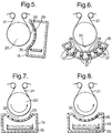
- the evaporator 15 has an arcuate array of nozzles similar to that shown in Fig 4 and is located at one side of the chilled drum 20, so that the vapour from the nozzles 29 is directed in a generally horizontal direction against the web substrate 21 in the deposition zone 30.
- One or more evaporators 15 may be orientated around the drum 20, effectively enlarging the deposition zone.
- the evaporator 15 contains 6 retorts 37 each containing a crucible 35 containing material to be vaporised and having a single nozzle 29, the nozzles being disposed sequentially and terminating on an arc around the deposition zone 30.
- the crucibles 35 are heated by a common heating means; they need not contain identical materials.
- the evaporator 15 is similar to that shown in figs 4 and 5 but the width of the sequence of nozzles 29 is progressively increased. This is advantageous for the application of heavy coatings which add to the thermal mass of the web. As the coating is progressively built-up the web is able to withstand more heat load for a given temperature rise so that more material may be deposited, in this case by a progressive widening of the nozzles.
- the evaporator 15 is similar to that shown in Fig 7,but the width of the nozzles 29 remains constant and the nozzle spacing is progressively reduced, thereby giving the same advantage for heavy coating as the modification of Fig. 7.
- the modification shown in Fig. 9 illustrates how the nozzle direction can be varied to control the direction in which the vapour impinges on the web substrate. In some cases this may affect the properties of the coating.
- the nozzle direction may also be varied to prevent unvaporised particles travelling directly from the surface of material in the crucible 35 to the web substrate at the deposition zone 30 and adversely affecting the quality of the coating.
- the nozzle array shown in Fig. 10 consists of lines of spaced nozzles 29 of circular cross section arranged in a sequence of lines lying transverse to the direction of the web substrate advance, the nozzle outlets lying on an arcuate surface.
- the nozzle array shown in Fig. 11 consists of a sequence of slots orientated in the direction of the web substrate advance with the nozzle outlets on an arcuate surface and the slots being in sequence transverse to the direction of the web substrate advance.
- the temperature of the retorts was 630°C and a 3.0 micron thick coating of zinc was deposited on the paper, the variation of the coating being ⁇ 5% by weight over the area of the web.
- the coating process could be commenced 22 minutes after the start of heating the evaporator and evacuating the vacuum chamber. Evaporation of the zinc could be stopped instantaneously by feeding argon gas at a pressure 700 - 900 millibars around the nozzle exits. By circulating argon gas around the retorts the evaporator could be cooled in 40 minutes to a temperature at which the uncoated paper supply and the zinc in the retorts could safely be replenished.
Landscapes
- Chemical & Material Sciences (AREA)
- Chemical Kinetics & Catalysis (AREA)
- Engineering & Computer Science (AREA)
- Materials Engineering (AREA)
- Mechanical Engineering (AREA)
- Metallurgy (AREA)
- Organic Chemistry (AREA)
- Physical Vapour Deposition (AREA)
Applications Claiming Priority (2)
| Application Number | Priority Date | Filing Date | Title |
|---|---|---|---|
| GB939323034A GB9323034D0 (en) | 1993-11-09 | 1993-11-09 | Vacuum web coating |
| GB9323034 | 1993-11-09 |
Publications (2)
| Publication Number | Publication Date |
|---|---|
| EP0652302A1 true EP0652302A1 (de) | 1995-05-10 |
| EP0652302B1 EP0652302B1 (de) | 1997-10-08 |
Family
ID=10744843
Family Applications (1)
| Application Number | Title | Priority Date | Filing Date |
|---|---|---|---|
| EP94308157A Expired - Lifetime EP0652302B1 (de) | 1993-11-09 | 1994-11-04 | Vakuumbeschichtung von Bahnen |
Country Status (7)
| Country | Link |
|---|---|
| EP (1) | EP0652302B1 (de) |
| JP (1) | JPH07286272A (de) |
| KR (1) | KR950014355A (de) |
| CA (1) | CA2135424A1 (de) |
| DE (1) | DE69406084T2 (de) |
| ES (1) | ES2108387T3 (de) |
| GB (2) | GB9323034D0 (de) |
Cited By (13)
| Publication number | Priority date | Publication date | Assignee | Title |
|---|---|---|---|---|
| EP0756020A1 (de) * | 1995-07-28 | 1997-01-29 | Balzers und Leybold Deutschland Holding Aktiengesellschaft | Verfahren und Vorrichtung zur Herstellung von metallfreien Streifen bei der Metallbedampfung |
| GB2306173A (en) * | 1995-10-11 | 1997-04-30 | Leybold Ag | Coating plant with pivotting contact rollers |
| GB2306172A (en) * | 1995-10-11 | 1997-04-30 | Leybold Ag | Coating plant with dismountable guide rollers |
| US5803976A (en) * | 1993-11-09 | 1998-09-08 | Imperial Chemical Industries Plc | Vacuum web coating |
| EP1004369A1 (de) * | 1998-11-26 | 2000-05-31 | Recherche et Développement GROUPE COCKERILL SAMBRE | Abgedichtete Schleuse für eine Vakuumkammer |
| GB2346897A (en) * | 1999-02-18 | 2000-08-23 | Leybold Systems Gmbh | Vapourisation device |
| US6202591B1 (en) | 1998-11-12 | 2001-03-20 | Flex Products, Inc. | Linear aperture deposition apparatus and coating process |
| WO2003035925A1 (fr) * | 2001-10-26 | 2003-05-01 | Matsushita Electric Works, Ltd. | Dispositif et procede de metallisation sous vide, element electroluminescent organique produit par ledit dispositif et procede associe |
| EP1803836A1 (de) * | 2005-12-28 | 2007-07-04 | Samsung SDI Co., Ltd. | Verdampfungsquelle und Verfahren zum Ablagern eines Dünnfilms damit |
| CN102482762A (zh) * | 2010-06-16 | 2012-05-30 | 松下电器产业株式会社 | 薄膜的制造方法 |
| CN102482763A (zh) * | 2010-06-16 | 2012-05-30 | 松下电器产业株式会社 | 薄膜的制造方法 |
| CN103649364A (zh) * | 2011-07-07 | 2014-03-19 | 松下电器产业株式会社 | 真空蒸镀装置 |
| CN103898450A (zh) * | 2012-12-25 | 2014-07-02 | 北京汉能创昱科技有限公司 | 一种铜铟镓硒共蒸发线性源装置及其使用方法 |
Families Citing this family (6)
| Publication number | Priority date | Publication date | Assignee | Title |
|---|---|---|---|---|
| KR100389377B1 (ko) * | 2000-07-20 | 2003-06-25 | 한국전력공사 | 고전압 분압 및 전류 공급용 전왜 세라믹스 조성물 및 제조방법 |
| KR101730498B1 (ko) * | 2010-10-22 | 2017-04-27 | 삼성디스플레이 주식회사 | 유기층 증착 장치 및 이를 이용한 유기 발광 디스플레이 장치의 제조 방법 |
| JP5883230B2 (ja) * | 2011-03-14 | 2016-03-09 | キヤノントッキ株式会社 | 蒸着装置並びに蒸着方法 |
| JP2012201895A (ja) * | 2011-03-23 | 2012-10-22 | Canon Tokki Corp | 蒸着装置並びに蒸着方法 |
| JP6110664B2 (ja) * | 2013-01-07 | 2017-04-05 | 三菱重工業株式会社 | 蒸着用基板保持トレイを備える真空蒸着装置 |
| CN112553579B (zh) * | 2019-09-26 | 2023-05-09 | 宝山钢铁股份有限公司 | 一种具有过滤及均匀化喷嘴的真空镀膜装置 |
Citations (5)
| Publication number | Priority date | Publication date | Assignee | Title |
|---|---|---|---|---|
| US3081201A (en) * | 1957-05-15 | 1963-03-12 | Gen Electric | Method of forming an electric capacitor |
| US3748090A (en) * | 1971-12-20 | 1973-07-24 | Xerox Corp | Evaporation crucible |
| DE2436431A1 (de) * | 1974-07-29 | 1976-02-12 | Licentia Gmbh | Verdampfer zum herstellen von aufdampfschichten |
| JPS63297549A (ja) * | 1987-05-29 | 1988-12-05 | Komatsu Ltd | 真空蒸着装置 |
| JPH02118072A (ja) * | 1988-10-28 | 1990-05-02 | Mitsubishi Heavy Ind Ltd | 真空蒸着装置 |
Family Cites Families (4)
| Publication number | Priority date | Publication date | Assignee | Title |
|---|---|---|---|---|
| GB304192A (en) * | 1928-01-16 | 1930-06-10 | Siemens Ag | Process for producing thin insulating layers on wires |
| GB962868A (en) * | 1961-09-29 | 1964-07-08 | Philips Electrical Ind Ltd | Improvements in or relating to coating objects with light-absorbing transparent or translucent colour layers |
| JPS5210869A (en) * | 1975-07-15 | 1977-01-27 | Toshinori Takagi | Thin film forming method |
| DE4104415C1 (de) * | 1991-02-14 | 1992-06-04 | 4P Verpackungen Ronsberg Gmbh, 8951 Ronsberg, De |
-
1993
- 1993-11-09 GB GB939323034A patent/GB9323034D0/en active Pending
-
1994
- 1994-11-02 GB GB9422076A patent/GB2283760A/en not_active Withdrawn
- 1994-11-04 ES ES94308157T patent/ES2108387T3/es not_active Expired - Lifetime
- 1994-11-04 EP EP94308157A patent/EP0652302B1/de not_active Expired - Lifetime
- 1994-11-04 DE DE69406084T patent/DE69406084T2/de not_active Expired - Fee Related
- 1994-11-09 KR KR1019940029248A patent/KR950014355A/ko not_active IP Right Cessation
- 1994-11-09 CA CA002135424A patent/CA2135424A1/en not_active Abandoned
- 1994-11-09 JP JP6274804A patent/JPH07286272A/ja active Pending
Patent Citations (5)
| Publication number | Priority date | Publication date | Assignee | Title |
|---|---|---|---|---|
| US3081201A (en) * | 1957-05-15 | 1963-03-12 | Gen Electric | Method of forming an electric capacitor |
| US3748090A (en) * | 1971-12-20 | 1973-07-24 | Xerox Corp | Evaporation crucible |
| DE2436431A1 (de) * | 1974-07-29 | 1976-02-12 | Licentia Gmbh | Verdampfer zum herstellen von aufdampfschichten |
| JPS63297549A (ja) * | 1987-05-29 | 1988-12-05 | Komatsu Ltd | 真空蒸着装置 |
| JPH02118072A (ja) * | 1988-10-28 | 1990-05-02 | Mitsubishi Heavy Ind Ltd | 真空蒸着装置 |
Non-Patent Citations (2)
| Title |
|---|
| PATENT ABSTRACTS OF JAPAN vol. 013, no. 134 (C - 581) 4 April 1989 (1989-04-04) * |
| PATENT ABSTRACTS OF JAPAN vol. 014, no. 326 (C - 0740) 12 July 1990 (1990-07-12) * |
Cited By (23)
| Publication number | Priority date | Publication date | Assignee | Title |
|---|---|---|---|---|
| US5803976A (en) * | 1993-11-09 | 1998-09-08 | Imperial Chemical Industries Plc | Vacuum web coating |
| EP0756020A1 (de) * | 1995-07-28 | 1997-01-29 | Balzers und Leybold Deutschland Holding Aktiengesellschaft | Verfahren und Vorrichtung zur Herstellung von metallfreien Streifen bei der Metallbedampfung |
| GB2306173A (en) * | 1995-10-11 | 1997-04-30 | Leybold Ag | Coating plant with pivotting contact rollers |
| GB2306172A (en) * | 1995-10-11 | 1997-04-30 | Leybold Ag | Coating plant with dismountable guide rollers |
| GB2306172B (en) * | 1995-10-11 | 1999-03-17 | Leybold Ag | Coating plant for coating films |
| GB2306173B (en) * | 1995-10-11 | 1999-05-05 | Leybold Ag | Coating plant for coating films |
| US6202591B1 (en) | 1998-11-12 | 2001-03-20 | Flex Products, Inc. | Linear aperture deposition apparatus and coating process |
| US6367414B2 (en) | 1998-11-12 | 2002-04-09 | Flex Products, Inc. | Linear aperture deposition apparatus and coating process |
| US6334751B1 (en) | 1998-11-26 | 2002-01-01 | RECHERCHE ET DEVELOPPMENT DU GROUPE COCKERILL SAMBRE, EN ABRéGé RD-CS | Air lock |
| EP1004369A1 (de) * | 1998-11-26 | 2000-05-31 | Recherche et Développement GROUPE COCKERILL SAMBRE | Abgedichtete Schleuse für eine Vakuumkammer |
| US6309466B1 (en) | 1999-02-18 | 2001-10-30 | Leybold Systems Gmbh | Vapor deposition apparatus |
| GB2346897A (en) * | 1999-02-18 | 2000-08-23 | Leybold Systems Gmbh | Vapourisation device |
| WO2003035925A1 (fr) * | 2001-10-26 | 2003-05-01 | Matsushita Electric Works, Ltd. | Dispositif et procede de metallisation sous vide, element electroluminescent organique produit par ledit dispositif et procede associe |
| CN1302149C (zh) * | 2001-10-26 | 2007-02-28 | 松下电工株式会社 | 真空蒸镀装置、真空蒸镀方法及获得的有机电子荧光元件 |
| EP1803836A1 (de) * | 2005-12-28 | 2007-07-04 | Samsung SDI Co., Ltd. | Verdampfungsquelle und Verfahren zum Ablagern eines Dünnfilms damit |
| CN102482762A (zh) * | 2010-06-16 | 2012-05-30 | 松下电器产业株式会社 | 薄膜的制造方法 |
| CN102482763A (zh) * | 2010-06-16 | 2012-05-30 | 松下电器产业株式会社 | 薄膜的制造方法 |
| US8865258B2 (en) | 2010-06-16 | 2014-10-21 | Panasonic Corporation | Method of manufacturing thin film which suppresses unnecessary scattering and deposition of a source material |
| US8877291B2 (en) | 2010-06-16 | 2014-11-04 | Panasonic Corporation | Method of manufacturing thin film which suppresses unnecessary scattering and deposition of a source material |
| CN102482763B (zh) * | 2010-06-16 | 2015-04-08 | 松下电器产业株式会社 | 薄膜的制造方法 |
| CN103649364A (zh) * | 2011-07-07 | 2014-03-19 | 松下电器产业株式会社 | 真空蒸镀装置 |
| CN103898450A (zh) * | 2012-12-25 | 2014-07-02 | 北京汉能创昱科技有限公司 | 一种铜铟镓硒共蒸发线性源装置及其使用方法 |
| CN103898450B (zh) * | 2012-12-25 | 2017-06-13 | 北京创昱科技有限公司 | 一种铜铟镓硒共蒸发线性源装置及其使用方法 |
Also Published As
| Publication number | Publication date |
|---|---|
| GB9422076D0 (en) | 1994-12-21 |
| EP0652302B1 (de) | 1997-10-08 |
| ES2108387T3 (es) | 1997-12-16 |
| DE69406084T2 (de) | 1998-03-12 |
| GB9323034D0 (en) | 1994-01-05 |
| JPH07286272A (ja) | 1995-10-31 |
| DE69406084D1 (de) | 1997-11-13 |
| CA2135424A1 (en) | 1995-05-10 |
| GB2283760A (en) | 1995-05-17 |
| KR950014355A (ko) | 1995-06-16 |
Similar Documents
| Publication | Publication Date | Title |
|---|---|---|
| US5803976A (en) | Vacuum web coating | |
| EP0652302B1 (de) | Vakuumbeschichtung von Bahnen | |
| US5000114A (en) | Continuous vacuum vapor deposition system having reduced pressure sub-chambers separated by seal devices | |
| EP0652303B1 (de) | Vakuumverdampfer zum Beschichten einer Bahn | |
| US4543275A (en) | Method of forming thin vapor deposited film of organic material | |
| US7339139B2 (en) | Multi-layered radiant thermal evaporator and method of use | |
| US8425738B2 (en) | Method for depositing of barrier layers on a plastic substrate as well as coating device therefor and a layer system | |
| US3181209A (en) | Foil production | |
| WO1998001596A1 (en) | Production of nanometer particles by directed vapor deposition of electron beam evaporant | |
| EP0629715A1 (de) | Verfahren und Vorrichtung zur kontinuerlichen reaktiven Metallbeschichtung im Vacuum | |
| RU2221080C2 (ru) | Устройство для нанесения вакуумным способом покрытия на подшипники скольжения | |
| CN115698370A (zh) | 用于蒸发源的温度控制遮蔽件、用于在基板上沉积材料的材料沉积设备及方法 | |
| EP1804306B1 (de) | Anlage zur kontinuierlichen Herstellung eines Supraleiterbandes | |
| US5620576A (en) | Method of and apparatus for producing a thin layer of a material on a substrate | |
| CN206109530U (zh) | 用于将工艺气体供应到蒸发器源中的气体注入器单元 | |
| JP3399570B2 (ja) | 連続真空蒸着装置 | |
| JP5239483B2 (ja) | 金属酸化物薄膜付きシートの製造方法および製造装置 | |
| NL8201093A (nl) | Inrichting voor het aanbrengen van dunne lagen. | |
| JP2023538027A (ja) | 少なくとも1つの加熱アセンブリを有する材料堆積装置並びに基板を予加熱及び/又は後加熱するための方法 | |
| EP4012067B1 (de) | Vakuumbeschichtungsvorrichtung | |
| JPS6320447A (ja) | 金属帯を連続的にセラミツクでコ−テイングする方法と装置 | |
| KR20240090967A (ko) | 박막 기판을 운송하기 위한 진공 처리 시스템, 장치 및 방법 | |
| JPH08246149A (ja) | 真空蒸着装置 | |
| CN117795120A (zh) | 用于有效的表面区域蒸发的蒸发器 | |
| WO2024091610A1 (en) | Centrifugal atomization of molten metal |
Legal Events
| Date | Code | Title | Description |
|---|---|---|---|
| PUAI | Public reference made under article 153(3) epc to a published international application that has entered the european phase |
Free format text: ORIGINAL CODE: 0009012 |
|
| AK | Designated contracting states |
Kind code of ref document: A1 Designated state(s): BE DE ES FR GB IT NL SE |
|
| 17P | Request for examination filed |
Effective date: 19951030 |
|
| 17Q | First examination report despatched |
Effective date: 19960617 |
|
| GRAG | Despatch of communication of intention to grant |
Free format text: ORIGINAL CODE: EPIDOS AGRA |
|
| GRAH | Despatch of communication of intention to grant a patent |
Free format text: ORIGINAL CODE: EPIDOS IGRA |
|
| RAP1 | Party data changed (applicant data changed or rights of an application transferred) |
Owner name: IMPERIAL CHEMICAL INDUSTRIES PLC |
|
| GRAH | Despatch of communication of intention to grant a patent |
Free format text: ORIGINAL CODE: EPIDOS IGRA |
|
| GRAA | (expected) grant |
Free format text: ORIGINAL CODE: 0009210 |
|
| AK | Designated contracting states |
Kind code of ref document: B1 Designated state(s): BE DE ES FR GB IT NL SE |
|
| PG25 | Lapsed in a contracting state [announced via postgrant information from national office to epo] |
Ref country code: NL Free format text: LAPSE BECAUSE OF FAILURE TO SUBMIT A TRANSLATION OF THE DESCRIPTION OR TO PAY THE FEE WITHIN THE PRESCRIBED TIME-LIMIT Effective date: 19971008 |
|
| PGFP | Annual fee paid to national office [announced via postgrant information from national office to epo] |
Ref country code: FR Payment date: 19971110 Year of fee payment: 4 |
|
| REF | Corresponds to: |
Ref document number: 69406084 Country of ref document: DE Date of ref document: 19971113 |
|
| PGFP | Annual fee paid to national office [announced via postgrant information from national office to epo] |
Ref country code: SE Payment date: 19971117 Year of fee payment: 4 |
|
| PGFP | Annual fee paid to national office [announced via postgrant information from national office to epo] |
Ref country code: DE Payment date: 19971124 Year of fee payment: 4 |
|
| ET | Fr: translation filed | ||
| PGFP | Annual fee paid to national office [announced via postgrant information from national office to epo] |
Ref country code: ES Payment date: 19971128 Year of fee payment: 4 |
|
| PGFP | Annual fee paid to national office [announced via postgrant information from national office to epo] |
Ref country code: BE Payment date: 19971201 Year of fee payment: 4 |
|
| ITF | It: translation for a ep patent filed | ||
| REG | Reference to a national code |
Ref country code: ES Ref legal event code: FG2A Ref document number: 2108387 Country of ref document: ES Kind code of ref document: T3 |
|
| NLV1 | Nl: lapsed or annulled due to failure to fulfill the requirements of art. 29p and 29m of the patents act | ||
| PLBE | No opposition filed within time limit |
Free format text: ORIGINAL CODE: 0009261 |
|
| STAA | Information on the status of an ep patent application or granted ep patent |
Free format text: STATUS: NO OPPOSITION FILED WITHIN TIME LIMIT |
|
| 26N | No opposition filed | ||
| PG25 | Lapsed in a contracting state [announced via postgrant information from national office to epo] |
Ref country code: GB Free format text: LAPSE BECAUSE OF NON-PAYMENT OF DUE FEES Effective date: 19981104 |
|
| PG25 | Lapsed in a contracting state [announced via postgrant information from national office to epo] |
Ref country code: SE Free format text: LAPSE BECAUSE OF NON-PAYMENT OF DUE FEES Effective date: 19981105 Ref country code: ES Free format text: LAPSE BECAUSE OF NON-PAYMENT OF DUE FEES Effective date: 19981105 |
|
| PG25 | Lapsed in a contracting state [announced via postgrant information from national office to epo] |
Ref country code: BE Free format text: LAPSE BECAUSE OF NON-PAYMENT OF DUE FEES Effective date: 19981130 |
|
| BERE | Be: lapsed |
Owner name: IMPERIAL CHEMICAL INDUSTRIES P.L.C. Effective date: 19981130 |
|
| GBPC | Gb: european patent ceased through non-payment of renewal fee |
Effective date: 19981104 |
|
| PG25 | Lapsed in a contracting state [announced via postgrant information from national office to epo] |
Ref country code: FR Free format text: LAPSE BECAUSE OF NON-PAYMENT OF DUE FEES Effective date: 19990730 |
|
| EUG | Se: european patent has lapsed |
Ref document number: 94308157.0 |
|
| REG | Reference to a national code |
Ref country code: FR Ref legal event code: ST |
|
| PG25 | Lapsed in a contracting state [announced via postgrant information from national office to epo] |
Ref country code: DE Free format text: LAPSE BECAUSE OF NON-PAYMENT OF DUE FEES Effective date: 19990901 |
|
| REG | Reference to a national code |
Ref country code: ES Ref legal event code: FD2A Effective date: 19991214 |
|
| PG25 | Lapsed in a contracting state [announced via postgrant information from national office to epo] |
Ref country code: IT Free format text: LAPSE BECAUSE OF NON-PAYMENT OF DUE FEES;WARNING: LAPSES OF ITALIAN PATENTS WITH EFFECTIVE DATE BEFORE 2007 MAY HAVE OCCURRED AT ANY TIME BEFORE 2007. THE CORRECT EFFECTIVE DATE MAY BE DIFFERENT FROM THE ONE RECORDED. Effective date: 20051104 |