EP0651384A2 - Verfahren zur Prüfung von Bandanfang und Bandende für Datenaufzeichnungs- und Wiedergebegerät - Google Patents
Verfahren zur Prüfung von Bandanfang und Bandende für Datenaufzeichnungs- und Wiedergebegerät Download PDFInfo
- Publication number
- EP0651384A2 EP0651384A2 EP94402453A EP94402453A EP0651384A2 EP 0651384 A2 EP0651384 A2 EP 0651384A2 EP 94402453 A EP94402453 A EP 94402453A EP 94402453 A EP94402453 A EP 94402453A EP 0651384 A2 EP0651384 A2 EP 0651384A2
- Authority
- EP
- European Patent Office
- Prior art keywords
- tape
- checking
- supply reel
- reel
- rotation period
- Prior art date
- Legal status (The legal status is an assumption and is not a legal conclusion. Google has not performed a legal analysis and makes no representation as to the accuracy of the status listed.)
- Withdrawn
Links
Images

Classifications
-
- G—PHYSICS
- G11—INFORMATION STORAGE
- G11B—INFORMATION STORAGE BASED ON RELATIVE MOVEMENT BETWEEN RECORD CARRIER AND TRANSDUCER
- G11B15/00—Driving, starting or stopping record carriers of filamentary or web form; Driving both such record carriers and heads; Guiding such record carriers or containers therefor; Control thereof; Control of operating function
- G11B15/02—Control of operating function, e.g. switching from recording to reproducing
- G11B15/05—Control of operating function, e.g. switching from recording to reproducing by sensing features present on or derived from record carrier or container
- G11B15/087—Control of operating function, e.g. switching from recording to reproducing by sensing features present on or derived from record carrier or container by sensing recorded signals
-
- G—PHYSICS
- G11—INFORMATION STORAGE
- G11B—INFORMATION STORAGE BASED ON RELATIVE MOVEMENT BETWEEN RECORD CARRIER AND TRANSDUCER
- G11B15/00—Driving, starting or stopping record carriers of filamentary or web form; Driving both such record carriers and heads; Guiding such record carriers or containers therefor; Control thereof; Control of operating function
- G11B15/02—Control of operating function, e.g. switching from recording to reproducing
- G11B15/05—Control of operating function, e.g. switching from recording to reproducing by sensing features present on or derived from record carrier or container
- G11B15/06—Control of operating function, e.g. switching from recording to reproducing by sensing features present on or derived from record carrier or container by sensing auxiliary features on record carriers or containers, e.g. to stop machine near the end of a tape
- G11B15/08—Control of operating function, e.g. switching from recording to reproducing by sensing features present on or derived from record carrier or container by sensing auxiliary features on record carriers or containers, e.g. to stop machine near the end of a tape by photoelectric sensing
-
- G—PHYSICS
- G11—INFORMATION STORAGE
- G11B—INFORMATION STORAGE BASED ON RELATIVE MOVEMENT BETWEEN RECORD CARRIER AND TRANSDUCER
- G11B15/00—Driving, starting or stopping record carriers of filamentary or web form; Driving both such record carriers and heads; Guiding such record carriers or containers therefor; Control thereof; Control of operating function
- G11B15/02—Control of operating function, e.g. switching from recording to reproducing
- G11B15/05—Control of operating function, e.g. switching from recording to reproducing by sensing features present on or derived from record carrier or container
- G11B15/093—Control of operating function, e.g. switching from recording to reproducing by sensing features present on or derived from record carrier or container by sensing driving condition of record carrier, e.g. travel, tape tension
-
- G—PHYSICS
- G11—INFORMATION STORAGE
- G11B—INFORMATION STORAGE BASED ON RELATIVE MOVEMENT BETWEEN RECORD CARRIER AND TRANSDUCER
- G11B27/00—Editing; Indexing; Addressing; Timing or synchronising; Monitoring; Measuring tape travel
- G11B27/10—Indexing; Addressing; Timing or synchronising; Measuring tape travel
- G11B27/11—Indexing; Addressing; Timing or synchronising; Measuring tape travel by using information not detectable on the record carrier
- G11B27/13—Indexing; Addressing; Timing or synchronising; Measuring tape travel by using information not detectable on the record carrier the information being derived from movement of the record carrier, e.g. using tachometer
- G11B27/17—Indexing; Addressing; Timing or synchronising; Measuring tape travel by using information not detectable on the record carrier the information being derived from movement of the record carrier, e.g. using tachometer using electrical sensing means
-
- G—PHYSICS
- G11—INFORMATION STORAGE
- G11B—INFORMATION STORAGE BASED ON RELATIVE MOVEMENT BETWEEN RECORD CARRIER AND TRANSDUCER
- G11B27/00—Editing; Indexing; Addressing; Timing or synchronising; Monitoring; Measuring tape travel
- G11B27/10—Indexing; Addressing; Timing or synchronising; Measuring tape travel
- G11B27/34—Indicating arrangements
-
- G—PHYSICS
- G11—INFORMATION STORAGE
- G11B—INFORMATION STORAGE BASED ON RELATIVE MOVEMENT BETWEEN RECORD CARRIER AND TRANSDUCER
- G11B2220/00—Record carriers by type
- G11B2220/90—Tape-like record carriers
Definitions
- the present invention relates in general to a method for checking top and end of a tape for data recording and reproducing apparatus and, more particularly, to an improvement in the top-end checking method for making the top-end checking time become optimal and for saving power of the recording and reproducing apparatus, and for reducing the pulse noise generated in turning on and turning off a top-end checking LED.
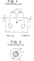
- a general theory for checking tape top and tape end for data recording and reproducing apparatus in accordance with the prior art.
- a tape cassette 1 having a top-end LED hole T-EH on the upper center of its bottom surface is loaded on a deck mechanism of the apparatus, a light emit part 4 which comprises an LED and is provided on the deck mechanism will be aligned with the center of the top-end LED hole T-EH of the cassette 1.
- the opposite front side surfaces of the cassette 1 are provided with their light windows 3 and 3' for transmitting the light of the light emit part 4 to their associated light receive parts 5 and 5', which parts 5 and 5' are arranged on the deck mechanism so that they face the light windows 3 and 3' of the cassette 1 respectively.
- the deck mechanism of the data recording and reproducing apparatus further includes a head drum 2 which is placed in front of the loaded cassette 1.
- the head drum 2 has a head for recording or reproducing data on or from a tape of the cassette 1.
- the light emit part 4 aligned with the center of the top-end LED hole of the cassette 1 emits the light.
- the first reel and the second reel of the cassette 1 of Fig. 1 be a tape supply reel and a tape take-up reel respectively, and letting the tape be primarily unwound from the first reel and be wound about the second reel, a first transparent tape section provided on the start portion of the tape appears and passes by the right window 3 of the cassette 1.
- the light of the light emit part 4 of the deck mechanism which was introduced into the hole T-EH of the cassette 1 is received by the light receive part 5 of the right side through both the first transparent tape section and the right window 3.
- the magnetic coated tape section passes by the right window 3 after lapse of a predetermined time, the light of the light emit part 4 will not be transmitted to the light receive part 5 of the right side any more as the light can not be transmitted through the magnetic coated tape section.
- the light receive part 5 of the right side will recognize the tape top.
- the light receive part 5' of the left side receives the light of the light emit part 4 through both a second transparent tape section provided on the end portion of the tape and the left window 3'.
- the light receive part 5' of the left side will recognize the tape end.
- the tape runs in the reversed direction such as in a REWIND mode of the deck mechanism
- the light receive part 5' of the left side will recognize the tape top, while the light receive part 5 of the right side will recognize the tape end.
- the above tape top and tape end checking method has a problem. That is, the distance between the light emit part 4 and each of the light receive parts 5 and 5' is longer than half of the length of the cassette 1. Due to the longer distance between the light emit part 4 and each light receive part 5 or 5', large amount of electric current should be sent to the LED of the light emit part 4 in order for letting the part 4 emit sufficient light.
- the typical checking method for tape top and tape end should be accompanied by waste of large amount of electric power and this causes a serious problem in the data recording and reproducing apparatus.
- portable VCRs such as camera-integrated VCRs should be reduced in their effective filming time since substantial part of charged electric power of them is consumed for checking the tape top and tape end.
- the top-end checking LED is limited in its life span, so that the LED may be short-lived when the LED is turned on continuously for checking the tape top and tape end.
- the LED may be repeatedly turned on and turned off at regular time intervals.
- pulse noise is generated.
- an object of the invention to provide a method for checking top and end of tape for data recording and reproducing apparatus in which the above problems can be overcome and which detects, after sensing the tape top by a tape top sensor, a tape supply reel rotation period and checks the tape end at a predetermined checking period when the detected reel rotation period is not longer than a preset value.
- a method for checking top and end of tape for data recording and reproducing apparatus comprising: a first step for sensing a transparent tape section of a start portion of a tape wound about a tape take-up reel so as to sense the tape top; a second step for detecting a tape supply reel rotation period and for comparing the detected supply reel rotation period to a preset value; and a third step for checking the tape end at a predetermined period when the detected supply reel rotation period is not longer than the preset value, but checking no tape end when the detected supply reel rotation period is longer than the preset value.
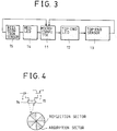
- Fig. 3 is a block diagram of a circuit for checking tape top and tape end for data recording and reproducing apparatus in accordance with a preferred embodiment of the invention.
- the checking circuit includes a microcomputer 11 for controlling the operation for checking the tape top and tape end.
- a top-end checking light emit diode 12 (hereinbelow, referred to simply as “the top-end LED”) is coupled to the microcomputer 11 and emits light in response to a control signal of the microcomputer 11.
- the checking circuit also includes a top-end sensor 13 which senses the light of the top-end LED 12 and applies light sensing signals to the microcomputer 11.
- the microcomputer 11 is also coupled to a reel LED 14 which emits light in response to a control signal of the microcomputer 11.
- the checking circuit further includes a reel rotation sensor 15 which senses the light of the reel LED 14 and applies light sensing signals to the microcomputer 11.
- the microcomputer 11 In order to check the tape top and tape end as well as to sense a reel rotation, the microcomputer 11 outputs control signals to the top-end LED 12 and to the reel LED 14, so that the LEDs 12 and 14 emit their lights.
- the reel LED emits its light as shown in Fig. 4 showing the relation between the reel LED 14, the reel rotation sensor 15 and a reel plate
- the light absorption sectors of the reel plate absorb the light of the reel LED 14, which reel plate is rotated along with the reel.
- a light reflection sectors of the reel plate reflect the light of the reel LED.
- the reel rotation sensor 15 which senses the light reflected by reflections sections of the reel plate, outputs signals in form of low signal - high signal - low signal - high signal to the microcomputer 11, thus to let the microcomputer 11 recognize the reel rotation.
- the top-end sensor 13 senses the light of the top-end LED 12 and outputs its signal to the microcomputer 11, thus to let the microcomputer 11 recognize the tape top or tape end.
- the tape supply reel rotation period will be detected as follows.
- the tape amount supplied by the supply reel is equal to the tape amount wound about the hub of the take-up reel. That is, as shown in Fig. 2, the supplied tape amount will be equal to the result of subtraction of the area A' of the tape wound about the take-up reel from the area A of the tape, which area A is an area of the tape when all the tape is wound about the supply reel.
- the tape running velocity V is preset for respective velocities of operational modes of the deck mechanism.
- the tape running time t is zero, so that a supply reel hub rotation period T HUB obtained when only the supply reel hub is rotated with no tape wound about the supply reel will be obtained from the equation 3.
- This reel hub rotation period T HUB is represented by the following equation on the base of the equation 2.
- T HUB 2 ⁇ Ro/V
- the optimal time for checking the tape end is preferably set in the manner that the tape end is sensed when the supply reel period T is slightly longer than the reel hub rotation period T HUB in the case of all tape unwound from the supply reel.
- the optimal time for checking the tape end is practically set in the manner that the tape end is sensed when the supply reel period T is slightly shorter than T HUB + t1.
- the tape end checking period T1 otherwise stated, the period for turning on the top-end LED 12 is that the shorter of the length L1 of the transparent tape section provided on the end portion of the tape and the length L2 of the tape passage between the drum 3 and the tape supply reel is shorter than the tape supply period. This is for preventing the transparent tape section from coming into contact with the head of the drum and for letting the transparent tape section give no damage to the head.
- the LED turning on time T on for checking tape top and tape end is set in accordance with characteristics of the top-end LED 12 as well as of the top-end sensor 13.
- T HUB + t1 The LED turning on time T on for checking tape top and tape end is set in accordance with characteristics of the top-end LED 12 as well as of the top-end sensor 13.
- the smallest tape thickness 7 ⁇ m of an 8 mm tape will be preferably used.
- the total time for turning on LED, T LED-ON was about 100 msec.
- the resistance of the top-end LED 12 be 200 ⁇ and the voltage of the LED 12 be 5V
- the electric current which should be sent to the top-end LED 12 was 25 mA, so that 25 mAh of energy was consumed when the top-end LED 12 was continuously turned on while using an one hour running tape cassette.
- the checking method of the invention consumed only 0.6 ⁇ Ah of energy under the same condition.
- the instant checking method preferably lengthened the expected life span of the top-end LED 12 by 36,000 times in comparison with when the LED 12 was continuously turned on.
- Fig. 5 is a flowchart showing the method for checking tape top and tape end for data recording and reproducing apparatus according to the invention.
- the supply reel rotation period T is detected at first.
- the detected period T is, thereafter, compared with the preset value T HUB + t1.
- the tape end is not checked.
- the detected period T is not longer than the preset value T HUB + t1
- the tape end is checked by turning on the top-end LED 12 for the predetermined time T on .
- the tape end is checked by the tape end checking period T1 or by the period for turning on the top-end LED 12 which is that the shorter of the length L1 of the transparent tape section provided on the end portion of the tape or the length L2 of the tape passage between the drum 3 and the tape supply reel is shorter than the tape supply period.
- the method for checking tape top and tape end for data recording and reproducing apparatus of the invention makes top-end checking time become optimal and saves power of the recording and reproducing apparatus, and reduces pulse noise generated in turning on or turning off the top-end checking LED.
Landscapes
- Indexing, Searching, Synchronizing, And The Amount Of Synchronization Travel Of Record Carriers (AREA)
- Television Signal Processing For Recording (AREA)
- Optical Recording Or Reproduction (AREA)
Applications Claiming Priority (2)
| Application Number | Priority Date | Filing Date | Title |
|---|---|---|---|
| KR93023131A KR960008370B1 (en) | 1993-11-02 | 1993-11-02 | Start/end checking method for record player |
| KR9323131 | 1993-11-02 |
Publications (2)
| Publication Number | Publication Date |
|---|---|
| EP0651384A2 true EP0651384A2 (de) | 1995-05-03 |
| EP0651384A3 EP0651384A3 (de) | 1995-11-29 |
Family
ID=19367215
Family Applications (1)
| Application Number | Title | Priority Date | Filing Date |
|---|---|---|---|
| EP94402453A Withdrawn EP0651384A3 (de) | 1993-11-02 | 1994-10-28 | Verfahren zur Prüfung von Bandanfang und Bandende für Datenaufzeichnungs- und Wiedergebegerät. |
Country Status (3)
| Country | Link |
|---|---|
| US (1) | US5617336A (de) |
| EP (1) | EP0651384A3 (de) |
| KR (1) | KR960008370B1 (de) |
Families Citing this family (2)
| Publication number | Priority date | Publication date | Assignee | Title |
|---|---|---|---|---|
| US5801893A (en) * | 1996-07-01 | 1998-09-01 | Ford Motor Company | Method for adaptively detecting tapewrap in cassette tape player |
| US7048219B2 (en) * | 2002-10-10 | 2006-05-23 | Samsung Electronics Co., Ltd. | Reel clutch of a tape recorder |
Family Cites Families (11)
| Publication number | Priority date | Publication date | Assignee | Title |
|---|---|---|---|---|
| US3730453A (en) * | 1970-09-21 | 1973-05-01 | Xerox Corp | Early end of tape detection |
| US3834648A (en) * | 1972-03-15 | 1974-09-10 | Ampex | Apparatus and method for sensing diameter of tape pack on storage reel |
| JPS6022417B2 (ja) * | 1979-04-24 | 1985-06-01 | 松下電器産業株式会社 | 磁気記録再生装置 |
| JPS55146639A (en) * | 1979-05-02 | 1980-11-15 | Olympus Optical Co Ltd | Tape end detector |
| JPS5740777A (en) * | 1980-08-22 | 1982-03-06 | Victor Co Of Japan Ltd | High-speed tape feed system of recordng and reproducing device |
| JPS5746342A (en) * | 1980-09-04 | 1982-03-16 | Hitachi Ltd | Detector for specific position on magnetic tape |
| JPS58220259A (ja) * | 1982-06-15 | 1983-12-21 | Victor Co Of Japan Ltd | テ−プ端検出装置 |
| JPH0337854A (ja) * | 1989-07-05 | 1991-02-19 | Matsushita Electric Ind Co Ltd | テープ端検出装置 |
| JPH03250444A (ja) * | 1990-02-27 | 1991-11-08 | Sharp Corp | 磁気記録再生装置のテープ端検出回路 |
| US5309300A (en) * | 1991-08-06 | 1994-05-03 | R-Byte, Inc. | Beginning/end of tape detection system |
| JPH0612730A (ja) * | 1992-06-30 | 1994-01-21 | Olympus Optical Co Ltd | テープ端検出装置 |
-
1993
- 1993-11-02 KR KR93023131A patent/KR960008370B1/ko not_active Expired - Fee Related
-
1994
- 1994-10-28 EP EP94402453A patent/EP0651384A3/de not_active Withdrawn
- 1994-10-28 US US08/330,564 patent/US5617336A/en not_active Expired - Fee Related
Also Published As
| Publication number | Publication date |
|---|---|
| KR960008370B1 (en) | 1996-06-26 |
| US5617336A (en) | 1997-04-01 |
| EP0651384A3 (de) | 1995-11-29 |
| KR950015297A (ko) | 1995-06-16 |
Similar Documents
| Publication | Publication Date | Title |
|---|---|---|
| EP0651384A2 (de) | Verfahren zur Prüfung von Bandanfang und Bandende für Datenaufzeichnungs- und Wiedergebegerät | |
| AU7116487A (en) | Method and apparatus for detecting position of tape when recording or reproducing signals thereon | |
| US5608584A (en) | Recognition of tape recording media type using plural in-line holes | |
| US4011586A (en) | Voice logging recorder for use with preloaded cassettes | |
| JPH0418383B2 (de) | ||
| JPH01165057A (ja) | テープカセット種別検出装置 | |
| KR0183111B1 (ko) | 테이프의 주행 제어방법 | |
| US6285518B1 (en) | Life/wear monitoring for magnetic tape | |
| US6459541B1 (en) | Magnetic recording and reproducing apparatus arranged to save electric power consumed in detecting tape end and reduce load on microprocessor | |
| US6257515B1 (en) | Magnetic recording and reproducing apparatus detecting end of tape by counting motor signals per supply-reel revolution | |
| JPH0612730A (ja) | テープ端検出装置 | |
| KR100195614B1 (ko) | 카세트의 허브크기 판별방법 | |
| US5815336A (en) | Method for sensing position of magnetic tape during discontinuous travel of the tape | |
| US20020060877A1 (en) | Media identification for magnetic tape drive | |
| KR100195616B1 (ko) | 비디오 테이프의 시작 및 끝부분 검출방법 | |
| JP2542798Y2 (ja) | デジタルオーディオテープレコーダにおけるカセットハーフ検出装置 | |
| JPH08273245A (ja) | リールテーブルの回転速度検出装置 | |
| KR980011188A (ko) | 비디오 테이프의 시작 및 끝부분 검출방법 | |
| KR100253152B1 (ko) | 테이프의 주행 제어 장치 및 방법 | |
| KR0162609B1 (ko) | 테이프 주행 제어방법 | |
| US5555141A (en) | Apparatus for electrically detecting starting/ending portions of a tape | |
| KR930007934B1 (ko) | 로직 카세트 플레이어에서의 모드별 헤드위치 감지방법 | |
| KR100209188B1 (ko) | 브이씨알의 테이프 이상 주행 제어장치 | |
| JPS5826098B2 (ja) | カセツト型リ−ル駆動磁気テ−プ移送装置 | |
| KR19990033551A (ko) | 자기기록재생기의 테이프 단부 검출방법 |
Legal Events
| Date | Code | Title | Description |
|---|---|---|---|
| PUAI | Public reference made under article 153(3) epc to a published international application that has entered the european phase |
Free format text: ORIGINAL CODE: 0009012 |
|
| AK | Designated contracting states |
Kind code of ref document: A2 Designated state(s): DE FR GB |
|
| PUAL | Search report despatched |
Free format text: ORIGINAL CODE: 0009013 |
|
| AK | Designated contracting states |
Kind code of ref document: A3 Designated state(s): DE FR GB |
|
| RAP1 | Party data changed (applicant data changed or rights of an application transferred) |
Owner name: LG ELECTRONICS INC. |
|
| 17P | Request for examination filed |
Effective date: 19960309 |
|
| 17Q | First examination report despatched |
Effective date: 19980916 |
|
| STAA | Information on the status of an ep patent application or granted ep patent |
Free format text: STATUS: THE APPLICATION IS DEEMED TO BE WITHDRAWN |
|
| 18D | Application deemed to be withdrawn |
Effective date: 19990127 |