EP0650797B1 - Procédé et appareil pour séparer un embout d'électrode thermo-adhérant - Google Patents
Procédé et appareil pour séparer un embout d'électrode thermo-adhérant Download PDFInfo
- Publication number
- EP0650797B1 EP0650797B1 EP94307424A EP94307424A EP0650797B1 EP 0650797 B1 EP0650797 B1 EP 0650797B1 EP 94307424 A EP94307424 A EP 94307424A EP 94307424 A EP94307424 A EP 94307424A EP 0650797 B1 EP0650797 B1 EP 0650797B1
- Authority
- EP
- European Patent Office
- Prior art keywords
- electrode tip
- welding gun
- workpiece
- servo motor
- welding
- Prior art date
- Legal status (The legal status is an assumption and is not a legal conclusion. Google has not performed a legal analysis and makes no representation as to the accuracy of the status listed.)
- Expired - Lifetime
Links
Images


Classifications
-
- B—PERFORMING OPERATIONS; TRANSPORTING
- B23—MACHINE TOOLS; METAL-WORKING NOT OTHERWISE PROVIDED FOR
- B23K—SOLDERING OR UNSOLDERING; WELDING; CLADDING OR PLATING BY SOLDERING OR WELDING; CUTTING BY APPLYING HEAT LOCALLY, e.g. FLAME CUTTING; WORKING BY LASER BEAM
- B23K11/00—Resistance welding; Severing by resistance heating
- B23K11/10—Spot welding; Stitch welding
- B23K11/11—Spot welding
-
- B—PERFORMING OPERATIONS; TRANSPORTING
- B23—MACHINE TOOLS; METAL-WORKING NOT OTHERWISE PROVIDED FOR
- B23K—SOLDERING OR UNSOLDERING; WELDING; CLADDING OR PLATING BY SOLDERING OR WELDING; CUTTING BY APPLYING HEAT LOCALLY, e.g. FLAME CUTTING; WORKING BY LASER BEAM
- B23K11/00—Resistance welding; Severing by resistance heating
- B23K11/30—Features relating to electrodes
- B23K11/31—Electrode holders and actuating devices therefor
- B23K11/314—Spot welding guns, e.g. mounted on robots
Definitions
- the present invention relates to a method and apparatus for separating a welding electrode tip from a workpiece when the electrode tip has temperature adhered to the workpiece.
- Automobile body panels are spot welded using a welding apparatus which includes a general purpose robot having six degrees of freedom and a spot-welding gun coupled to a wrist portion of the robot.
- the conventional spot-welding gun pressurizes a workpiece between a pair of electrode tips by reciprocally moving one of the electrode tips by an air cylinder.
- a servo-welding gun having a pair of electrode tips, one of which is driven by a servo motor was proposed by the present applicant in Japanese Patent Application No. 4-94916 filed on March 23, 1992.
- DE-A-3,047,913 discloses a device for signalling the presence of a temperature-adhering welding electrode tip on a workpiece, and the necessity to separate the workpiece from the electrode tip.
- An object of the present invention is to provide a method and apparatus for separating a temperature-adhered electrode tip of a servo-welding gun from a workpiece without causing a defect to the workpiece when electrode tip and the workpiece are moved relative to each other.
- Another object of the present invention is to provide a method and apparatus for automatically separating an electrode tip of a servo-welding gun from a workpiece when a temperature-adhered electrode tip has been detected.
- the invention provides a method for separating a temperature-adhered welding electrode tip from a workpiece in accordance with Claim 1.
- the invention also provides an apparatus for separating a temperature-adhered welding electrode tip from a workpiece in accordance with Claim 7 or Claim 8.
- the present invention includes four embodiments. Throughout all descriptions of the embodiments of the present invention, portions having common or similar structures are denoted with the same reference numerals.
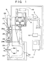
- spot welding of a workpiece 6, for example, an automobile body is conducted at welding points using a welding robot 1.
- a servo-welding gun 2 is coupled to a wrist portion 5 of the welding robot 1.
- the welding gun 2 has a pair of electrode tips 3 and 4, one of which is driven by a servo motor 26.
- the pair of electrode tips 3 and 4 holds the workpiece 6 by pressing the workpiece 6 therebetween and then spot welds the workpiece 6 by pressing an electric current between the electrode tips 3 and 4.
- the welding robot 1 is a general purpose robot having six degrees of freedom, for example, six articulations 8A to 8F.
- the wrist portion 5 and the welding gun 2 can be moved to any position (x, y, z) and any attitude ( ⁇ x , ⁇ y , ⁇ z ) desired.
- the welding gun 2 is controlled by a control unit 7 (FIG. 1).
- the welding points are programmed in the control unit 7. Once programmed, the control unit 7 moves the welding gun 2 to the programmed points to perform spot welding.
- the welding gun 2 has a generally C-shaped framework 22.
- a tip holder 24 is coupled to one leg portion of the C-shaped framework 22 and holds an electrode tip 4.
- the welding gun servo motor 26 is connected to the other leg portion.
- a threaded rod 28 of a ball screw coupling is coupled to rotational shaft 21 of the servo motor 26 via a coupling 27.
- the threaded rod 28 is supported rotatably by bearings 29a and 29b which are connected to the C-shaped framework 29.
- a nut 25 is coupled rotatably to the threaded rod 28 via ball elements of the ball screw coupling so that the nut 25 is moved in an axial direction of the threaded rod 28 by powering the servo motor 26 and rotating the threaded rod 28.
- Another tip holder 23, connected to the electrode tip 3 is coupled to the nut 25 via a connecting member. Thus, the electrode tip 3 is moved by operating the servo motor 26.
- An encoder 9 is interfaced to the servo motor 26 and detects the rotational angle of the servo motor 26. With such data, the position of the electrode tip 3 along the threaded rod 28 can be determined. An output of the data from the encoder 9 is fed to the control unit 7. The axial position of the electrode tip 3 may be detected by devices other than the encoder, for example, a linear motor.
- the electrode tips 3 and 4 are connected electrically to a welding transformer 11 via a cable 10.
- the welding transformer 11 is connected electrically to a welding power source (not shown) via a controller 12 having a timer function.
- the controller 12 is connected electrically then to the control unit 7 so that a welding time period in accordance with the timer function is controlled by the control unit 7.
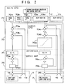
- the control unit 7 includes a main CPU (central processing unit) 72, a servo CPU 73, an interface 74, a servo amplifier 75, and an alert device 71.
- the main CPU 72 includes a first raceway track section 72a for calculating and indicating a raceway track position R of the wrist 5 of the welding robot 1, a second raceway track section 72b for calculating and indicating a raceway track position, R*G, of the electrode tip 3, a pressure force section 72c for calculating a pressure force for the electrode tip 3, an alert section 72d for determining whether or not an abnormal weld condition (i.e., temperature adhesion) has occurred, and a separation method selection and control section 72e for selecting a suitable separation routine and conducting the selected routine.
- the alert section 72d is linked to the separation method selection and control section 72e and outputs to the alert device 71. When the alert section 72d determines that a temperature adhesion has occurred, the alert device 71 expresses the occurrence of the temperature adhesion.
- the servo CPU 73 includes two sections 73a and 73b for calculating differentials between (a) instruction or control values for a position and a speed of the robot wrist 5 sent from the first raceway track section 72a and (b) actual values for a position and a speed of the robot wrist 5 as reported by a positional sensor 13 and a speed sensor 14 coupled to each servo motor 16 of each welding robot articulation 8A to 8F.
- Servo CPU sections 73a and 73b also control each servo motor 16 so that the above differentials become zero.
- the servo CPU 73 further includes sections 73c and 73d for calculating differentials between (a) instruction or control values for a position and a speed of the electrode tip 3 sent from the second raceway track section 72b and (b) actual values for a position and a speed of the electrode tip 3 as reported by the encoder 9 and the speed sensor 15. Sections 73c and 73d also control the servo motor 26 so that the above differentials become zero.
- the servo CPU 73 includes a section 73e for comparing an actual pressure force value calculated from an actual electric current of the servo motor 26 with an instruction pressure force value sent from the main CPU 72, and for controlling the actual pressure force to become equal to the instruction pressure force.
- the interface 74 includes a digital/analogue converter for converting a digital signal from the servo CPU 73 to an analogue signal.
- the servo amplifier 75 includes a section 75d for detecting an electric current flowing in each servo motor 16 and a section 75a for controlling the electric current of the servo motor 16 based on a differential between the detected actual electric current and an instruction electric current for the servo motor 16.
- the servo amplifier 75 includes an electric current detecting sensor 75b for detecting an electric current flowing in the servo motor 26 for moving the electrode tip 3, and a portion 75c for controlling the electric current of the servo motor 26 based on a differential between an actual electric current value fed back from the sensor 75b and an instruction value.
- a signal from the electric current detecting sensor 75b and a signal from the encoder 9 representing position are fed to the alert section 72d of the main CPU 72. Based on these inputs, the alert section 72d determines whether a temperature adhesion has occurred. When the section 72d determines that a temperature adhesion has occurred, it sends a signal to the alert device 71 which in turn annunciates the occurrence of the temperature adhesion. The section 72d also sends the signal to the separation method selection and control section 72e. Thereafter, the selectional control section 72e selects a separation control routine from control routines (routines of four embodiments of the present invention) stored in a RAM of the control unit 7 and controls the selected separation method.
- control routines routines of four embodiments of the present invention
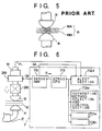
- the alert section 72d is illustrated in FIGS. 5 to 8.
- temperature adhesion of the electrode tip 3 to the workpiece 6 including panels 6A and 6B is visually determined.
- automatic detection for temperature adhesion is desirable.
- a differential between an instruction position P CMD and an actual position P E for the servo motor 26, and an actual electric current iM of the servo motor 26 are monitored.
- P E - P CMD exceeds a first threshold P THR
- the servo motor electric current iM exceeds a second threshold iM THR
- temperature adhesion of the electrode tips 3 and 4 with the workpiece 6 has occurred.
- the temperature adhesion occurrence is then indicated by the alert device 71.
- it is possible to detect the temperature adhesion by monitoring a differential between the actual position P E with the instructed position P CMD alone, without necessarily checking the electrical current iM.
- the alert section 72d is installed in the main CPU 72.
- a signal P E from the encoder 9, and a signal iM from the electric current detecting sensor 75b are reported to the alert section 72d.
- the instruction position P CMD of the electrode tip sent from the raceway track sections 72a and 72b of the main CPU 72 is reported also to the alert section 72d.
- FIG. 7 illustrates corresponding changes in the actual position P E of the electrode tip 3 and the actual electric current iM of the servo motor 26 in a case when temperature adhesion occurs.
- the electrode tip 3 begins to move toward the workpiece 6 and thereafter comes into contact with the workpiece 6 at point S 2 . Then, between points S 2 and S 3 , a welding current flows between the pair of electrode tips 3 and 4 so that the workpiece 6 is spot welded. The electrode tip 3 begins to move away from the workpiece 6 at point S 3 . In a normal condition where no temperature adhesion occurs, as illustrated by dotted line L 1 (instructed position P CMD ), the electrode tip 3 can move away from the workpiece 6.
- FIG. 9 illustrates a control routine for automatically detecting a temperature adhesion and successively selecting and conducting a separation method.
- This control routine is cycled at small time intervals.
- an instruction position P CMD of the electrode tip 3 sent from the second raceway section 72b, an actual position P E from the encoder 9, and an actual servo motor electric current iM from the electric current detecting sensor 75b are retrieved.
- the control routine determines whether a differential between P E and P CMD exceeds a first threshold P THR and/or whether the actual electric current iM exceeds a second threshold iM THR .
- the step 52 forms the alert section 72d as a combination of a position differential determination and an electric current determination.
- the alert section may be constructed of a position differential determination only.
- step 53 When the position differential exceeds the first threshold and/or the electric current exceeds the second threshold, temperature adhesion is indicated, and the routine proceeds to step 53 where the alert device 71 indicates that a temperature adhesion has occurred.
- the control routine proceeds to step 54 where a suitable separation method is selected from the control routines (control routines of FIGS. 10, 11, 13, 15, 17) stored in the RAM of the control unit 7, and the selected routine is thereafter conducted.
- step 55 the control routine determines whether the temperature-adhered electrode tip has been separated from the workpiece. If the electrode is not separated from the workpiece, step 55 cycles the control routine back to step 54 until the electrode tip is separated from the workpiece. When the electrode tip 3 is separated from the workpiece, the routine proceeds to step 56 wherein completion of the welding process is verified.
- the steps 54 and 55 correspond to the separation method selection and control section 72e.
- step 52 if either the positional differential or the electric current does not exceed its corresponding threshold, the routine proceeds to step 56, where the control routine determines whether the spot welding has been finished and the pressure released. If the pressure has not been released, the routine goes back to step 51 and the cycle is repeated. In contrast, when welding has been finished and the pressure released, the cycle ends, and the welding gun 2 is moved by the welding robot 1 to the next spot welding point.
- the separation method selection and control step 54 is generally indicated in FIG. 10.
- the electrode tip 3 is biased perpendicularly away from the workpiece 6 by operating at least one of the robot servo motors 16 or the welding gun servo motor.
- the biasing method changes according to respective embodiments of the present invention.
- a separation force is imposed to the temperature-adhered electrode tip 3 while the tip 3 is being biased in the direction away from the workpiece 6 so that the electrode tip 3 is separated from the workpiece 6.
- the method for imposing separation forces changes according to respective embodiments of the present invention.
- the separation force may be a manually imposed hammering force or a mechanically imposed force. In the case of a mechanically imposed force, the separation can be automatic.
- the routine proceeds to step 63 where the routine returns to step 55 of FIG. 9.
- the workpiece 6 since the temperature-adhered electrode tip 3 is biased in the direction away from the workpiece 6, the workpiece 6 will not be injured by the electrode tip 3 even if either the electrode tip 3 or the workpiece 6 is laterally moved relative to the other during and/or after the separation.
- the electrode tip 3 is biased as described in FIG. 11. More particularly, at step 101, all of the robot servo motors 16 are powered off. When a worker enters the robot area, the welding gun servo motor 26 and all of the robot servo motors 16 are automatically powered off thereby preventing the worker from being hit by the robot. So, in a case where the worker enters the robot area to manually hammer the temperature-adhered portion, step 101 will be automatically conducted. Then, the routine proceeds to step 102 where the welding gun servo motor 26 only is powered on, either manually or automatically, to bias the electrode tip 3 in the direction away from the workpiece 6. Since the robot 1 is stopped and only the electrode tip 3 is biased in the direction perpendicular to the workpiece 6, the worker is protected from being hit by the robot 1. Then, the routine proceeds to step 62 of FIG. 10 - - execution of the separation force.
- a separation force is imposed on the adhering portion by, for example, hammering the temperature-adhered electrode tip 3 so that the electrode tip 3 is separated from the workpiece 6.
- the separation force of step 62 may be mechanically imposed, as illustrated in FIG. 12. Rods 43 and 44 of equalizing mechanisms 41 and 44 are moved toward the workpiece 6 thereby pushing and separating the workpiece 6 from the electrode tip 3.
- the separation force is mechanically imposed, the separation can be automatic.
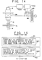
- the electrode tip 3 is biased as described in FIG. 13 and illustrated in FIG. 14. More particularly, at step 201, all of the robot servo motors 16 are powered off. Then, the routine proceeds to step 202 where a condenser battery 45 is discharged to the welding gun servo motor 26 (A.C. motor). Consequently, windings of the A.C. motor 26 are energized and the electrode tip 3 is biased in the direction away from the workpiece 6.
- the steps 201 and 202 correspond to step 61 of FIG. 10. Then, the routine proceeds to step 62 of FIG. 10 where the separation force is manually or mechanically imposed on the adhering portion.
- the separation force may be a hammering force manually imposed or a mechanical force automatically imposed as illustrated, for example, in FIG. 12. Further, the separation force may include the bias generated in the motor 26 by the discharged electricity. Moreover, if the electrode tip 3 is oscillated by increasing a gain during discharge, the separation will be easier.
- FIG. 14 illustrates the condenser battery 45 disposed in an electrical power circuit of the welding gun servo motor 26.
- the robot servo motors 16 are powered off and a switch 46 of the welding gun servo motor 26 is automatically opened.
- a switch 47 bypassing the switch 46 is closed so that the condenser battery 45 is discharged via the switch 47 to the welding gun servo motor 26. Since the discharged electric current is transitory, the welding gun servo motor 26 does not continue to rotate. A torque to rotate the servo motor 26, however, develops to sufficiently bias the electrode tip 3 in a direction away from the workpiece 6.
- the electrode tip 3 is biased in a direction away from the workpiece 6 and is separated automatically from the workpiece 6.
- the robot servo motor 16 and the welding gun servo motor 26 are not powered off for safety because a worker does not need to enter the robot area.
- the welding gun servo motor 26 is operated continually so that the electrode tip 3 is biased in a direction away from the workpiece 6.
- Step 301 corresponds to step 61 of FIG. 10.
- the routine proceeds to step 302 where the electrode tip 3 is rotated by about ten to twenty degrees about an axis of the electrode tip 3 by operating an electrode tip rotating device 30.
- the separation force includes the rotational force generated by the electrode tip rotating device 30.
- the rotational force is preferable over a lateral force such as a hammering force because defect are less likely to be generated in the workpiece 6.
- the step 302 corresponds to step 62 of FIG. 10.
- FIG. 16 illustrates the electrode tip rotating device 30 which includes an electrical motor.
- the rotational torque of the motor is transmitted to the tip holder 23 through engagement of gears 31 and 32.
- the electrode tip 3 is biased in a direction away from the workpiece 6 and is separated automatically from the workpiece 6.
- the robot servo motor 16 and the welding gun servo motor 26 are not powered off for safety because a worker does not need to enter the robot area.
- the welding gun servo motor 26 is operated continually so that the electrode tip 3 is biased in a direction away from the workpiece 6.
- Step 401 corresponds to step 61 of FIG. 10.
- the routine proceeds to step 402 where the electrode tip 3 is rotated by about ten to twenty degrees about an axis of the electrode tip 3 by operating all of the robot servo motors 16.
- the separation force includes the rotational force generated by the robot servo motors 16.
- the rotational force is preferable over a lateral force such as a hammering force because defects are less likely to be generated in the workpiece 6.
- the step 402 corresponds to step 62 of FIG. 10.
- FIG. 18 illustrates the biasing force and the rotational force acting on the electrode tip 3.
- the biasing force is generated by the welding gun servo motor 26 at step 401, and the rotational force is generated by the robot servo motors 16 at step 402.
- the rotational force has to be imposed on the electrode tip 3 while the biasing force is being imposed on the electrode tip 3.
- both electrode tips 3 and 4 may be driven by respective welding gun servo motors.
- the electrode tip 3 since the electrode tip 3 is biased in a direction away from the workpiece 6, a defect will not be caused in the workpiece 6 when either the electrode tip 3 or the workpiece 6 is moved relative to the other during and/or after separation.
Landscapes
- Engineering & Computer Science (AREA)
- Mechanical Engineering (AREA)
- Robotics (AREA)
- Resistance Welding (AREA)
Claims (8)
- Procédé servant à séparer une pointe d'électrode de soudage adhérant par température d'une pièce à usiner (6), dans lequel un pistolet à souder (2) est déplacé par un robot à souder (1) comprenant six articulations entraînées par des servomoteurs (16) de robot respectifs et le pistolet à souder (2) comprend une paire de pointes d'électrodes (3, 4) dont au moins une est entraînée par un servomoteur de pistolet à souder (26), ledit procédé étant caractérisé par les étapes consistant à :
solliciter la pointe d'électrode (3) dans une direction opposée et perpendiculaire à la pièce à usiner (6) en excitant au moins un des servomoteurs (16) du robot et le servomoteur (26) du pistolet à souder, et
imposer une force de séparation sur la pointe d'électrode adhérant par température tandis que la pointe d'électrode (3) est sollicitée dans la direction opposée à la pièce à usiner (6) afin de séparer la pointe d'électrode adhérant par température de la pièce à usiner (6). - Procédé selon la revendication 1, dans lequel pendant ladite étape de sollicitation, tous les servomoteurs (16) du robot sont coupés et seul le servomoteur (26) du pistolet à souder est excité.
- Procédé selon la revendication 1, dans lequel une batterie de condensateurs (45) est installée dans un circuit électrique comprenant le servomoteur (26) du pistolet à souder et dans lequel pendant ladite étape de sollicitation, tous les servomoteurs (16) du robot et le servomoteur (26) du pistolet à souder sont coupés et la batterie (45) est déchargée dans le servomoteur du pistolet à souder (26) pour solliciter la pointe d'électrode (3) dans la direction opposée à la pièce à usiner (6).
- Procédé selon la revendication 1, dans lequel pendant ladite étape d'imposition de la force de séparation, la force de séparation comprend également une force de rotation pour solliciter la pointe d'électrode adhérant par température dans un sens de rotation autour d'un axe de la pointe d'électrode (3).
- Procédé selon la revendication 4, dans lequel le pistolet à souder (2) comprend de plus un dispositif de rotation de pointe d'électrode (30) servant à faire tourner ladite au mains une pointe d'électrode (3) entraînée par le servomoteur (26) du pistolet à souder autour de l'axe de la pointe d'électrode (3) dans lequel ladite force de rotation de la force de séparation comprend une force de rotation produite par le dispositif de rotation de pointe d'électrode (30).
- Procédé selon la revendication 4, dans lequel ladite force de rotation de la force de séparation comprend une force de rotation produite par tous les servomoteurs (16) du robot.
- Appareil servant à séparer une pointe d'électrode de soudage adhérant par température d'une pièce à usiner (6) dans lequel un pistolet à souder (2) est déplacé par un robot à souder (1) comportant six articulations entraînées par des servomoteurs (16) de robot respectifs et le pistolet à souder (2) comporte une paires de pointes d'électrodes (3, 4) dont au moins une est entraînée par un servomoteur de pistolet à souder (26), ledit appareil étant caractérisé par :
une batterie de condensateurs (45) installée dans un circuit électrique comprenant le servomoteur (26) du pistolet à souder, la batterie de condensateurs (45) étant prévue pour se décharger dans le servomoteur du pistolet à souder (26) sur réception d'un signal de présence d'adhérence par température afin de solliciter la pointe d'électrode (3) adhérant de la pièce à usiner (6) dans une direction opposée et perpendiculaire à la pièce à usiner (6). - Appareil servant à séparer une pointe d'électrode de soudage adhérant par température, dans lequel un pistolet à souder (2) est déplacé par un robot à souder (1) comprenant six articulations entraînées par des servomoteurs (16) de robot respectifs et le pistolet à souder (2) comporte une paire de pointes d'électrodes (3, 4), dont au moins une est entraînée par un servomoteur (26) du pistolet à souder, ledit appareil étant caractérisé par :
un moyen servant à solliciter la pointe d'électrode (3) dans une direction opposée et perpendiculaire à la pièce à usiner (6) en excitant au moins un des servomoteurs du robot (16) et la servomoteur du pistolet à souder (26), et
un dispositif de rotation de pointe d'électrode (30) installé dans le pistolet à souder (2) servant à faire tourner ladite au moins une pointe d'électrode (3) entraînée par le servomoteur (26) du pistolet à souder autour d'un axe de la pointe d'électrode (3).
Applications Claiming Priority (2)
| Application Number | Priority Date | Filing Date | Title |
|---|---|---|---|
| JP05268650A JP3136865B2 (ja) | 1993-10-27 | 1993-10-27 | スポット溶接の溶着解除方法およびスポット溶接装置 |
| JP268650/93 | 1993-10-27 |
Publications (2)
| Publication Number | Publication Date |
|---|---|
| EP0650797A1 EP0650797A1 (fr) | 1995-05-03 |
| EP0650797B1 true EP0650797B1 (fr) | 1996-08-14 |
Family
ID=17461501
Family Applications (1)
| Application Number | Title | Priority Date | Filing Date |
|---|---|---|---|
| EP94307424A Expired - Lifetime EP0650797B1 (fr) | 1993-10-27 | 1994-10-10 | Procédé et appareil pour séparer un embout d'électrode thermo-adhérant |
Country Status (5)
| Country | Link |
|---|---|
| US (1) | US5510593A (fr) |
| EP (1) | EP0650797B1 (fr) |
| JP (1) | JP3136865B2 (fr) |
| KR (1) | KR0136356B1 (fr) |
| DE (1) | DE69400369T2 (fr) |
Families Citing this family (17)
| Publication number | Priority date | Publication date | Assignee | Title |
|---|---|---|---|---|
| JP3136282B2 (ja) * | 1997-08-13 | 2001-02-19 | ファナック株式会社 | サーボガン軸の異常負荷検出方法及び装置 |
| US6225590B1 (en) * | 1998-05-26 | 2001-05-01 | Medar, Inc. | Method for determining a condition of a resistance spotwelding system or a workpiece in the system |
| JP3761344B2 (ja) * | 1998-12-01 | 2006-03-29 | トヨタ自動車株式会社 | 溶接ガンとそれを用いたセンサー校正方法、溶接制御方法、溶接打点位置精度変化管理方法 |
| JP2000288743A (ja) * | 1999-02-03 | 2000-10-17 | Dengensha Mfg Co Ltd | 抵抗溶接機用制御装置 |
| JP2001170775A (ja) * | 1999-12-13 | 2001-06-26 | Obara Corp | 溶接装置の駆動装置 |
| FR2806951B1 (fr) * | 2000-03-31 | 2002-06-14 | Aro | Dispositif de motorisation electrique pour pince d'outillage |
| KR100354126B1 (ko) * | 2000-10-12 | 2002-09-28 | 한성엘컴텍 주식회사 | 콘덴서 어셈블리 설비 |
| DE10354526A1 (de) * | 2003-11-17 | 2005-06-23 | Bielomatik Leuze Gmbh + Co.Kg | Industrieroboter mit Reibschweißeinheit und Verfahren zur Steuerung |
| DE10360313B4 (de) * | 2003-12-18 | 2006-07-06 | PROMESS Gesellschaft für Montage- und Prüfsysteme mbH | Schweißvorrichtung |
| DE102005001341B3 (de) * | 2005-01-11 | 2006-10-05 | Kuka Schweissanlagen Gmbh | Verfahren und Vorrichtung zum elektrischen Punktschweißen |
| JP4943917B2 (ja) * | 2007-03-30 | 2012-05-30 | 本田技研工業株式会社 | 溶接装置及び溶接方法 |
| US8357871B2 (en) * | 2009-05-07 | 2013-01-22 | Innovative Weld Solutions Ltd. | Welding assembly and method |
| US8963043B2 (en) * | 2009-05-07 | 2015-02-24 | Innovative Weld Solutions, Ltd. | Welding assembly and associated method for welding and heat treating metals and metal alloys |
| JP5170175B2 (ja) * | 2010-06-30 | 2013-03-27 | 株式会社安川電機 | ロボットシステム |
| JP5638102B2 (ja) * | 2013-03-28 | 2014-12-10 | ファナック株式会社 | スポット溶接ガンを有するスポット溶接システム |
| KR20150120193A (ko) * | 2014-04-17 | 2015-10-27 | 현대자동차주식회사 | 프로젝션 용접건 장치 |
| DE102018200883A1 (de) * | 2018-01-19 | 2019-07-25 | Kuka Deutschland Gmbh | Roboterschweißen |
Family Cites Families (12)
| Publication number | Priority date | Publication date | Assignee | Title |
|---|---|---|---|---|
| DE299519C (fr) * | ||||
| JPS5756178A (en) * | 1980-09-22 | 1982-04-03 | Dengensha Mfg Co Ltd | Detection of melt-sticking of electrode tip for spot welding |
| DE3047913C2 (de) * | 1980-12-19 | 1982-09-02 | Volkswagenwerk Ag, 3180 Wolfsburg | "Schaltungsanordnung an einer elektrischen Schweißvorrichtung" |
| JPS61172686A (ja) * | 1985-01-24 | 1986-08-04 | Nissan Motor Co Ltd | 抵抗溶接機における電極チツプの溶着状態検知方法 |
| JPH0679788B2 (ja) * | 1988-02-23 | 1994-10-12 | 本田技研工業株式会社 | 自動溶接機の制御方法及びその制御装置 |
| JPH0741428B2 (ja) * | 1988-05-30 | 1995-05-10 | 三菱自動車工業株式会社 | スポットガンの溶着解除方法 |
| FR2652024B1 (fr) * | 1989-09-20 | 1992-04-24 | Aro Sa | Systeme de detalonnage pour pince a souder par resistance. |
| JP2521830B2 (ja) * | 1990-02-14 | 1996-08-07 | 川崎重工業株式会社 | 産業用ロボットの制御方法および装置 |
| JP3083101B2 (ja) * | 1990-08-15 | 2000-09-04 | 上野精機株式会社 | プレス装置 |
| JPH0547860A (ja) * | 1991-08-08 | 1993-02-26 | Shinkawa Ltd | ワイヤボンデイング方法 |
| JP2506402Y2 (ja) * | 1991-10-11 | 1996-08-07 | 川崎重工業株式会社 | スポット溶接ロボット用制御装置 |
| JPH05261560A (ja) * | 1992-03-23 | 1993-10-12 | Toyota Motor Corp | スポット溶接方法およびその装置 |
-
1993
- 1993-10-27 JP JP05268650A patent/JP3136865B2/ja not_active Expired - Lifetime
-
1994
- 1994-10-10 EP EP94307424A patent/EP0650797B1/fr not_active Expired - Lifetime
- 1994-10-10 DE DE69400369T patent/DE69400369T2/de not_active Expired - Lifetime
- 1994-10-25 US US08/328,529 patent/US5510593A/en not_active Expired - Lifetime
- 1994-10-27 KR KR1019940028583A patent/KR0136356B1/ko not_active Expired - Lifetime
Also Published As
| Publication number | Publication date |
|---|---|
| US5510593A (en) | 1996-04-23 |
| DE69400369T2 (de) | 1997-01-16 |
| DE69400369D1 (de) | 1996-09-19 |
| KR0136356B1 (ko) | 1998-11-16 |
| KR950011028A (ko) | 1995-05-15 |
| JPH07116864A (ja) | 1995-05-09 |
| JP3136865B2 (ja) | 2001-02-19 |
| EP0650797A1 (fr) | 1995-05-03 |
Similar Documents
| Publication | Publication Date | Title |
|---|---|---|
| EP0650797B1 (fr) | Procédé et appareil pour séparer un embout d'électrode thermo-adhérant | |
| EP0640428B1 (fr) | Méthode de contrÔle de soudage par points, ainsi que appareillage utilisant une pince de soudage asservie | |
| US5912539A (en) | Electric power steering apparatus | |
| US20040064228A1 (en) | Motor-driven power steering control apparatus | |
| US6118095A (en) | Control device for resistance welder | |
| EP0304491B1 (fr) | Direction assistee motorisee pour un vehicule et procede de commande | |
| CN113739843B (zh) | 电磁打桩锤的状态监测系统及状态监测方法 | |
| JPH0577755A (ja) | 電動パワーステアリング制御装置及び方法 | |
| JP3147603B2 (ja) | スポット溶接ガンの加圧制御方法およびその装置 | |
| JP3180530B2 (ja) | スポット溶接の散り発生抑制制御方法 | |
| JP3200825B2 (ja) | アーク溶接ロボットの制御方法及び装置 | |
| JPH0539885A (ja) | 電動バルブ | |
| JPH08212895A (ja) | スイッチ手段の故障検出装置 | |
| JP3755843B2 (ja) | 加圧型抵抗溶接機の制御方法 | |
| JPH10167162A (ja) | 電気自転車 | |
| JPH03222692A (ja) | ロボットの異常監視装置 | |
| JPH06298104A (ja) | 電動式パワーステアリング装置 | |
| JPS6114080A (ja) | 消耗電極式ア−ク溶接装置 | |
| JP3572801B2 (ja) | 電動パワーステアリング装置 | |
| JPH0780656A (ja) | 電極チップの溶着検知方法およびその装置 | |
| JP3166448B2 (ja) | スポット溶接方法 | |
| JPH0644531Y2 (ja) | スポット溶接機における溶着検出装置 | |
| JPH02198725A (ja) | ビス締め検知装置 | |
| JPH05319296A (ja) | モータ駆動式パワーステアリング制御装置 | |
| JPH0676934B2 (ja) | 締付け装置の作動検査方法 |
Legal Events
| Date | Code | Title | Description |
|---|---|---|---|
| PUAI | Public reference made under article 153(3) epc to a published international application that has entered the european phase |
Free format text: ORIGINAL CODE: 0009012 |
|
| 17P | Request for examination filed |
Effective date: 19941020 |
|
| AK | Designated contracting states |
Kind code of ref document: A1 Designated state(s): DE FR GB |
|
| 17Q | First examination report despatched |
Effective date: 19950710 |
|
| GRAG | Despatch of communication of intention to grant |
Free format text: ORIGINAL CODE: EPIDOS AGRA |
|
| GRAH | Despatch of communication of intention to grant a patent |
Free format text: ORIGINAL CODE: EPIDOS IGRA |
|
| GRAH | Despatch of communication of intention to grant a patent |
Free format text: ORIGINAL CODE: EPIDOS IGRA |
|
| GRAA | (expected) grant |
Free format text: ORIGINAL CODE: 0009210 |
|
| AK | Designated contracting states |
Kind code of ref document: B1 Designated state(s): DE FR GB |
|
| REF | Corresponds to: |
Ref document number: 69400369 Country of ref document: DE Date of ref document: 19960919 |
|
| ET | Fr: translation filed | ||
| PLBE | No opposition filed within time limit |
Free format text: ORIGINAL CODE: 0009261 |
|
| STAA | Information on the status of an ep patent application or granted ep patent |
Free format text: STATUS: NO OPPOSITION FILED WITHIN TIME LIMIT |
|
| 26N | No opposition filed | ||
| REG | Reference to a national code |
Ref country code: GB Ref legal event code: IF02 |
|
| REG | Reference to a national code |
Ref country code: GB Ref legal event code: 746 Effective date: 20030918 |
|
| REG | Reference to a national code |
Ref country code: FR Ref legal event code: D6 |
|
| REG | Reference to a national code |
Ref country code: FR Ref legal event code: ST Effective date: 20090630 |
|
| PG25 | Lapsed in a contracting state [announced via postgrant information from national office to epo] |
Ref country code: FR Free format text: LAPSE BECAUSE OF NON-PAYMENT OF DUE FEES Effective date: 20081031 |
|
| REG | Reference to a national code |
Ref country code: FR Ref legal event code: D3 |
|
| PGRI | Patent reinstated in contracting state [announced from national office to epo] |
Ref country code: FR Effective date: 20101103 |
|
| PGFP | Annual fee paid to national office [announced via postgrant information from national office to epo] |
Ref country code: GB Payment date: 20131009 Year of fee payment: 20 Ref country code: FR Payment date: 20131009 Year of fee payment: 20 Ref country code: DE Payment date: 20131002 Year of fee payment: 20 |
|
| REG | Reference to a national code |
Ref country code: DE Ref legal event code: R071 Ref document number: 69400369 Country of ref document: DE |
|
| REG | Reference to a national code |
Ref country code: GB Ref legal event code: PE20 Expiry date: 20141009 |
|
| PG25 | Lapsed in a contracting state [announced via postgrant information from national office to epo] |
Ref country code: GB Free format text: LAPSE BECAUSE OF EXPIRATION OF PROTECTION Effective date: 20141009 |