EP0647578B1 - Convoyeur du type caroussel, avec plusiers sorties, qui retient sélectivement les récipients à transporter - Google Patents
Convoyeur du type caroussel, avec plusiers sorties, qui retient sélectivement les récipients à transporter Download PDFInfo
- Publication number
- EP0647578B1 EP0647578B1 EP94112459A EP94112459A EP0647578B1 EP 0647578 B1 EP0647578 B1 EP 0647578B1 EP 94112459 A EP94112459 A EP 94112459A EP 94112459 A EP94112459 A EP 94112459A EP 0647578 B1 EP0647578 B1 EP 0647578B1
- Authority
- EP
- European Patent Office
- Prior art keywords
- carousel
- retaining
- container
- retaining element
- sliding part
- Prior art date
- Legal status (The legal status is an assumption and is not a legal conclusion. Google has not performed a legal analysis and makes no representation as to the accuracy of the status listed.)
- Expired - Lifetime
Links
- 238000007689 inspection Methods 0.000 claims description 7
- 238000006073 displacement reaction Methods 0.000 claims description 2
- 230000014759 maintenance of location Effects 0.000 claims 2
- 230000000717 retained effect Effects 0.000 claims 1
- 230000006978 adaptation Effects 0.000 abstract description 2
- 230000006835 compression Effects 0.000 description 2
- 238000007906 compression Methods 0.000 description 2
- 229910000639 Spring steel Inorganic materials 0.000 description 1
- 238000013016 damping Methods 0.000 description 1
- 230000001419 dependent effect Effects 0.000 description 1
- 230000002792 vascular Effects 0.000 description 1
- XLYOFNOQVPJJNP-UHFFFAOYSA-N water Substances O XLYOFNOQVPJJNP-UHFFFAOYSA-N 0.000 description 1
Images


Classifications
-
- B—PERFORMING OPERATIONS; TRANSPORTING
- B65—CONVEYING; PACKING; STORING; HANDLING THIN OR FILAMENTARY MATERIAL
- B65G—TRANSPORT OR STORAGE DEVICES, e.g. CONVEYORS FOR LOADING OR TIPPING, SHOP CONVEYOR SYSTEMS OR PNEUMATIC TUBE CONVEYORS
- B65G47/00—Article or material-handling devices associated with conveyors; Methods employing such devices
- B65G47/74—Feeding, transfer, or discharging devices of particular kinds or types
- B65G47/84—Star-shaped wheels or devices having endless travelling belts or chains, the wheels or devices being equipped with article-engaging elements
- B65G47/846—Star-shaped wheels or wheels equipped with article-engaging elements
- B65G47/847—Star-shaped wheels or wheels equipped with article-engaging elements the article-engaging elements being grippers
-
- B—PERFORMING OPERATIONS; TRANSPORTING
- B65—CONVEYING; PACKING; STORING; HANDLING THIN OR FILAMENTARY MATERIAL
- B65G—TRANSPORT OR STORAGE DEVICES, e.g. CONVEYORS FOR LOADING OR TIPPING, SHOP CONVEYOR SYSTEMS OR PNEUMATIC TUBE CONVEYORS
- B65G2201/00—Indexing codes relating to handling devices, e.g. conveyors, characterised by the type of product or load being conveyed or handled
- B65G2201/02—Articles
- B65G2201/0235—Containers
- B65G2201/0244—Bottles
Definitions
- the invention relates to a conveyor carousel with a plurality of outlets for selectively holding containers to be conveyed according to the preamble of claim 1 and claim 2. Furthermore, the invention relates to an inspection device for checking bottles with such a conveyor carousel.
- a sorting star for vascular treatment machines is known from DE-A 38 38 007.
- the individual containers are held in the pockets of the sorting star or carousel by means of rotary latches which execute a rotary movement in a plane parallel to the carousel axis.
- changing the bottle format e.g. from 1.5 liters to 0.5 liters, changing the entire carousel with many parts.
- the rotating bar creates scratches or other damage on the container surface.
- the invention is therefore based on the object of creating a possibility of holding the containers on the carousel, in which these disadvantages do not occur.
- the holding is preferably also carried out in such a way that the holding element essentially only touches the container at one point when it is held.
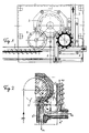
- an inspection machine for bottles e.g. shown for returnable PET bottles.
- the bottles pass through an inlet 1 onto an inlet carousel 2, a main carousel 3 and onto the outlet carousel 4.
- the bottles are subjected to various inspection steps which are known per se. For example, checked the height of the bottles, the presence of a cap, the presence of residual water, the presence of foreign bodies, etc.
- the outlet carousel 4 the bottles are then distributed upright to three different outlets 5, 6, 7.
- the outlets 5 and 6 should be provided for bottles which have not passed the inspections and the outlet 7 for defect-free bottles which are to be refilled.
- the holding elements described below are provided on the outlet carousel 4 so that the bottles can be held in the outlet carousel 4 up to their associated outlet in the carousel.
- FIG. 2 shows a further arrangement which can be provided for checking and / or sorting bottles.
- a main carousel 3 ' is also provided here, which feeds an outlet carousel 4'.
- Corresponding holding elements must also be provided in the distribution carousel 4 ', which hold the bottle in the carousel up to the outlet that is intended for it and release it at the outlet that is determined for it.
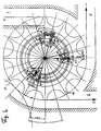
- FIG. 3 now shows a vertical section through an outlet carousel 4, the outlet carousel being shown on the left half of the figure in such a way that it is set for large bottles 10, for example 1.5 liter bottles, and is shown on the right side as follows. that it is set there for small bottles 11, for example 0.5 liter bottles.
- the carousel can be equipped on the one hand with two holding elements 12, 13 for large bottles and on the other hand with only one holding element 15 for small bottles.
- the receptacles (conveyor stars) 17 and 18 or 17 'and 18' which form the carousel pockets and which rotate around the central axis 19 of the carousel.
- the transducers 17 to 18 ' are interchangeable and adjustable in height to enable adaptation to different bottle sizes.
- a height-adjustable conveyor star 17''(only partially shown) engaging the bottle collar can also be provided, which is therefore format-independent and does not have to be replaced.
- control elements 20 and 21 which control the holding elements, are provided in a machine-fixed manner, ie not rotating with the carousel, which will be explained in more detail below.
- the control elements 20, 21 have electromagnetically or pneumatically extendable control bolts 22 and 23, which can be brought into engagement on control wings 24 and 25 for controlling the holding elements.
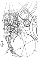
- control vanes 24 and 25 which are rotatably mounted on the carousel disk 26, undergo a rotary movement when they are moved past the extended bolts 22, 23 of the control devices by the carousel rotation. This is shown in a top view in FIG. 4, where three of the total of 12 control blades are shown in two different positions.
- the control wing 24 is shown in front of the outlet 6, which can be brought from the one position into the second position denoted by 24 'by the controllable bolt 22.
- the control wing 24 In the first position, designated by 24, the control wing 24 is positioned such that the associated cold element, still to be described, is in the carousel pocket holds the present object.
- control bolt 22 can thus be used to determine whether the container enters the outlet 6 or not.
- This control wing is controlled by the bolt 31. If this bolt is moved upwards, this results in a rotation of the control wing from position 30 to position 30 'and, as will be described in the following, a closing of the holding element, which thus holds the container.
- a first embodiment of the holding element actuated by the control levers will now be described with reference to FIG. 5 is dashed the control lever 30 is shown, which is rotatable about the axis 32 by the locking bolt 31.
- a gear segment 35 is held, which is designated in its one position as 35 and in its other position as 35 '.
- the position 35 corresponds to the closing of the holding element by the pin 31.
- the actual arc-shaped holding element 38 is actuated via a gear 36 meshing in the gear segment 35, which is provided in its rear region with a toothing 37 which meshes in the toothing of the gear 36 .
- the holding element 38 is provided with an exchangeable holding finger 39.
- the holding element 38 is extended from its retracted position between the successive bottles 10, 10 'over the front edge 40 of the carousel star in the plane of the carousel disc, that is to say in the plane perpendicular to the carousel axis to the front, if the closer pin 31 protrudes upwards and rotates the control lever 30 into position 30 'when it moves past it. Then there is the rotation of the gear segment from position 35 'to position 35 and thereby the extension of the holding element, which then touches the bottle 10' at point T with its finger 39 and holds it in the pocket of the carousel.
- FIG. 6 shows the same arrangement of the holding element 38, the same reference numerals as in FIG. 5 denoting the same parts.
- the holding element is provided with a modified finger 39 '.
- This allows holding smaller ones Bottles 11 and 11 '. It can thus be seen that in the holding device according to the invention, which extends in one plane of the carousel, the adjustment to the small bottle sizes can only be made by changing the front part 39 '.
- FIG. 7 shows a simplified embodiment of the holding element according to FIGS. 5 and 6. Again, the same reference numbers designate the same elements.
- the gear 36 is dispensed with. This results in a reversal of the movement of the control curve. Accordingly, the holding element is now extended by means of the control pin 31 ', which is arranged on the opposite side of the axis of rotation of the control cam 30, like the control pin 31 according to FIGS. 5 and 6.
- FIG. 8 shows a further embodiment of the holding element, in which case the rear part of the holding element adjoining the finger 39 is formed by a guided flexible element 40 '.
- this is a chain piece 40 'which is driven by a chain wheel 41.
- the chain wheel 41 in turn is actuated by the control wing, as has already been described with reference to the previous exemplary embodiments.
- a toothed belt or a spring steel band, a spring or a Bowden cable could also be used as the flexible element.
- This holding element also has the advantages mentioned that only the front part 39 needs to be changed when changing the bottle format and that the extension movement in the plane perpendicular to the carousel axis there is no risk of damage to the bottle to be held.
- FIG. 9 shows a further embodiment of the holding element.
- a control cam 51 or 51 ' is shown rotatably mounted on the axis of rotation 50, which is actuated by the control bolts in the manner already described.
- a rod 53 displaceable along a linear guide 52 is provided as the holding element.
- the rod 53 is provided with a pivoting part 54, to which the finger 39 is finally attached.
- the pivoting part 54 can be pivoted about an axis 55.
- the pivoting of the pivoting part 54 is derived from the linear movement of the rod 53 caused by the control wing by a control cam 56, in which a pin 57 of the pivoting part 54 engages.
- FIG. 10 shows the same embodiment as in FIG. 9, with a modified finger part 39 being fastened to the swivel part 54 in FIG. 10, which modified finger part allowing small bottles 11 'to be held.
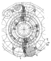
- FIG. 11 again shows a top view of the carousel with holding elements according to FIGS. 9 and 10, the holding elements which are provided with fingers for large bottles 10 being shown in the left half of FIG. 11 and the same holding elements in the right half of the figure are shown, which are provided with fingers for small bottles 11.
- FIG. 11 is only intended to clearly show once again that, in the holding elements according to the invention, only the finger part 39 needs to be replaced in order to adjust the holding elements to the other bottle size.
- FIG. 12 shows a representation similar to FIG. 11, in which case curved holding elements are provided, as have been described with reference to FIGS. 5 and 6. In this case, compression springs are also provided in these holding elements in order to keep them clearly defined in their guides.
- a non-round container 60 can also be held in the carousel by the holding elements according to the invention.
- the holding elements according to the invention or the carousel equipped with them are therefore not limited to round bottles, cans or similar containers, but square bottles, cans or other containers can also be securely held by the holding elements. This also applies to others e.g. triangular shapes.
Landscapes
- Engineering & Computer Science (AREA)
- Mechanical Engineering (AREA)
- Specific Conveyance Elements (AREA)
- Branching, Merging, And Special Transfer Between Conveyors (AREA)
- Sorting Of Articles (AREA)
- Supplying Of Containers To The Packaging Station (AREA)
- Control And Other Processes For Unpacking Of Materials (AREA)
Claims (9)
- Carrousel convoyeur comportant plusieurs sorties et une multitude d'éléments de retenue destinés à retenir de façon sélective des récipients à retenir, les éléments de retenue étant agencés en commun dans au moins un plan du carrousel et effectuant un mouvement dirigé essentiellement dans un plan perpendiculaire à l'axe du carrousel de manière à retenir ou à relâcher le récipient,
caractérisé en ce que chaque élément de retenue (38; 40'; 53, 54) comprend un élément coulisseau et un doigt de retenue (38, 39') fixé de façon remplaçable sur le coulisseau, le doigt constituant la partie d'extrémité avant de l' élément de retenue et la partie dépendant du format du récipient dans l'élément de retenue par ailleurs indépendant du format, et en ce que le carrousel convoyeur comporte d'autre part un élément de base indépendant du format des récipients, ainsi qu'une étoile de convoyeur supérieure et une étoile inférieure (17, 18) de convoyeur. - Carrousel convoyeur comportant plusieurs sorties et une multitude d'éléments de retenue destinés à retenir de façon sélective des récipients à retenir, les éléments de retenue étant agencés en commun dans au moins un plan du carrousel et effectuant un mouvement dirigé essentiellement dans un plan perpendiculaire à l'axe du carrousel de manière à retenir ou à relâcher le récipient,
caractérisé en ce que chaque élément de retenue (38; 40'; 53, 54) comprend un élément coulisseau et un doigt de retenue (38, 39') fixé de façon remplaçable sur le coulisseau, le doigt constituant la partie d'extrémité avant de l'élément de retenue et la partie dépendant du format du récipient dans l'élément de retenue par ailleurs indépendant du format, et en ce que le carrousel convoyeur comporte d'autre part un élément de base indépendant du format des récipients, une étoile de convoyeur supérieure (17'') indépendante du format, réglable en hauteur, ainsi qu'une étoile de convoyeur inférieure (18) dépendant du format. - Carrousel convoyeur selon la revendication 1 ou 2, caractérisé en ce que, pour le retenir, l'élément de retenue touche le récipient essentiellement en un seul point.
- Carrousel convoyeur selon la revendication 1 ou 2, caractérisé en ce que l'élément de retenue comporte un élément coulisseau droit (53) pouvant être déplacé, dans un guidage, dans le sens radial par rapport à l'axe du carrousel, ainsi qu'un doigt de retenue (39) monté de façon pivotante sur cet élément, qui, lors du mouvement coulissant de l'élément coulisseau, est mis en appui sur le récipient ou en est retiré, en étant guidé par une came de commande (56).
- Carrousel convoyeur selon la revendication 4, caractérisé en ce que l'élément coulisseau est maintenu dans le guidage par l'intermédiaire d'amortisseurs (58) à frottement.
- Carrousel convoyeur selon la revendication 1 ou 2, caractérisé en ce que l'élément de retenue (38) comporte un élément coulisseau rigide en forme d'arc et un doigt de retenue (39) monté sur ce dernier.
- Carrousel convoyeur selon la revendication 1 ou 2, caractérisé en ce que l'élément de retenue (40') comporte un élément coulisseau flexible coulissant dans un guidage, et un doigt de retenue monté sur celui-ci.
- Carrousel convoyeur selon la revendication 1 ou 2, caractérisé en ce que les éléments de retenue sont ouverts et fermés par l'intermédiaire d'ailes de commande (24, 25) couplées aux éléments de retenue, situées en dessous du plan du carrousel, les ailes de commande se déplaçant en rotation simultanément avec le carrousel et pouvant être amenées en prise avec des butées (22) stationnaires de la machine, qui peuvent être soit commandées, soit fixes, et qui impriment alors aux ailes un mouvement d'entraînement des éléments de retenue.
- Installation d'inspection pour le contrôle de bouteilles, utilisant un carrousel convoyeur selon l'une des revendications 1 à 8.
Applications Claiming Priority (4)
| Application Number | Priority Date | Filing Date | Title |
|---|---|---|---|
| CH301793 | 1993-10-07 | ||
| CH3017/93 | 1993-10-07 | ||
| CH335593 | 1993-11-08 | ||
| CH3355/93 | 1993-11-08 |
Publications (2)
| Publication Number | Publication Date |
|---|---|
| EP0647578A1 EP0647578A1 (fr) | 1995-04-12 |
| EP0647578B1 true EP0647578B1 (fr) | 1997-09-03 |
Family
ID=25691954
Family Applications (1)
| Application Number | Title | Priority Date | Filing Date |
|---|---|---|---|
| EP94112459A Expired - Lifetime EP0647578B1 (fr) | 1993-10-07 | 1994-08-10 | Convoyeur du type caroussel, avec plusiers sorties, qui retient sélectivement les récipients à transporter |
Country Status (12)
| Country | Link |
|---|---|
| US (1) | US5590753A (fr) |
| EP (1) | EP0647578B1 (fr) |
| JP (1) | JPH07187380A (fr) |
| CN (1) | CN1108207A (fr) |
| AT (1) | ATE157623T1 (fr) |
| BR (1) | BR9404008A (fr) |
| CA (1) | CA2130764A1 (fr) |
| DE (1) | DE59403952D1 (fr) |
| DK (1) | DK0647578T3 (fr) |
| FI (1) | FI944504A (fr) |
| NO (1) | NO943770L (fr) |
| PL (1) | PL305313A1 (fr) |
Families Citing this family (36)
| Publication number | Priority date | Publication date | Assignee | Title |
|---|---|---|---|---|
| NO303431B1 (no) * | 1996-07-12 | 1998-07-13 | Tomra Systems Asa | Anordning ved en transport°rinnretning |
| US7049911B2 (en) * | 2003-02-03 | 2006-05-23 | Leviton Manufacturing Co., Inc. | Circuit interrupting device and system utilizing electromechanical reset |
| US7737809B2 (en) * | 2003-02-03 | 2010-06-15 | Leviton Manufacturing Co., Inc. | Circuit interrupting device and system utilizing bridge contact mechanism and reset lockout |
| DE10311858B3 (de) * | 2003-03-17 | 2004-08-19 | Nexpress Solutions Llc | Vorrichtung zum Transport eines im wesentlichen bogenförmigen Elementes, insbesondere eines Bedruckstoffbogens |
| EP1663824B1 (fr) * | 2003-09-25 | 2009-06-17 | Diageo Plc | Transporteur a roues en etoile reglables |
| ITPD20060226A1 (it) * | 2006-06-06 | 2007-12-07 | Mbf Spa | Linea di trasportodi contenitori per impianti di imbottigliamento |
| JP4904992B2 (ja) * | 2006-08-25 | 2012-03-28 | 石井 登 | 回転式容器移送装置 |
| JP5110481B2 (ja) * | 2007-04-20 | 2012-12-26 | シデル パーティシペイションズ | ホイール垂直調整装置を備えるスターホイール搬送装置 |
| DE102008001285A1 (de) * | 2008-04-21 | 2009-10-22 | Robert Bosch Gmbh | Vorrichtung zum Transportieren eines Behälters |
| KR200449606Y1 (ko) | 2009-05-25 | 2010-07-23 | 김진갑 | 통합 조절식 스타휠 |
| DE202009019170U1 (de) | 2009-09-07 | 2017-07-07 | Krones Ag | Vorrichtung zum Herstellen von Kunstoffflaschen |
| US8813950B2 (en) | 2010-05-07 | 2014-08-26 | The Procter & Gamble Company | Automated adjustment system for star wheel |
| US8418836B2 (en) | 2010-05-07 | 2013-04-16 | The Procter & Gamble Company | Universally adjustable star wheel |
| DE102010049406A1 (de) * | 2010-10-26 | 2012-04-26 | Krones Aktiengesellschaft | Vorrichtung zum Transportieren von Behältnissen |
| DE102011001521B4 (de) * | 2011-03-24 | 2012-10-04 | Schuler Pressen Gmbh & Co. Kg | Vorrichtung und Verfahren zum Schneiden eines Dosenrohlings |
| NL2006649C2 (nl) * | 2011-04-20 | 2012-10-23 | Marel Townsend Further Proc Bv | Inrichting en werkwijze voor het overzetten van longitudinaal aangevoerde langwerpige voedselproducten. |
| CN102502168B (zh) * | 2011-10-14 | 2013-12-11 | 孟钧 | 一种保温瓶胆保温性能测试的传送装置 |
| US8499921B1 (en) | 2012-01-17 | 2013-08-06 | The Procter & Gamble Company | Adjustable guide rail assemblies |
| DE102013207267A1 (de) * | 2013-04-22 | 2014-10-23 | Krones Ag | Verstellbarer Klammerstern |
| DE102013104082B4 (de) * | 2013-04-23 | 2017-02-02 | Khs Gmbh | Transportvorrichtung für Behälter |
| ITVR20130155A1 (it) * | 2013-07-04 | 2015-01-05 | Pe Labellers Spa | Dispositivo di alimentazione ordinata di macchina confezionatrice di bottiglie e simili |
| CN103420098B (zh) * | 2013-08-16 | 2015-12-02 | 广州达意隆包装机械股份有限公司 | 输送瓶子的星轮传动机构 |
| US9181043B1 (en) | 2014-06-03 | 2015-11-10 | The Procter & Gamble Company | Elevation change system for a rotary device |
| US9302856B2 (en) | 2014-06-03 | 2016-04-05 | The Procter & Gamble Company | Method for adjusting a rotary device |
| US9371195B2 (en) | 2014-06-03 | 2016-06-21 | The Procter & Gamble Company | Adjustment system for a rotary device |
| ITUB20152731A1 (it) * | 2015-07-31 | 2017-01-31 | Ave Tech S R L | Apparecchiatura per la movimentazione di contenitori |
| EP3239078B1 (fr) * | 2016-04-28 | 2020-04-15 | Tyrolon-Schulnig GmbH | Dispositif de reglage en hauteur pour un dispositif de prehension et de transport destine a saisir, retenir, guide et transporter des recipients en forme de bouteille |
| US10315860B2 (en) | 2016-05-25 | 2019-06-11 | The Procter And Gamble Company | Article handling device |
| CN109353809B (zh) * | 2018-11-16 | 2024-02-13 | 湖南正中制药机械有限公司 | 一种多通道式大输液瓶出瓶装置 |
| DE102019106075A1 (de) | 2019-03-11 | 2020-09-17 | Khs Gmbh | Transportvorrichtung und Verfahren zum um eine vertikale Maschinenachse umlaufenden Transport von Behältern |
| JP7220104B2 (ja) * | 2019-03-20 | 2023-02-09 | 東洋ガラス株式会社 | 容器検査装置 |
| IT201900018218A1 (it) * | 2019-10-08 | 2021-04-08 | Sost S R L | Macchina e procedimento per la produzione di generi alimentari |
| CN110720484A (zh) * | 2019-10-29 | 2020-01-24 | 中国地质大学(武汉) | 一种面饼自动拨馅装置 |
| CN110789998A (zh) * | 2019-11-26 | 2020-02-14 | 昆山诚丰达工控设备有限公司 | 瓶体定向传递机构和传递方法 |
| CN111109629B (zh) * | 2020-01-13 | 2024-06-14 | 中国地质大学(武汉) | 一种用于面饼制作的自动拨馅装置 |
| MX2022011413A (es) | 2021-09-16 | 2023-03-17 | Fogg Filler Company Llc | Sistema de transferencia de material giratorio con ajuste y componentes de sistema relacionados. |
Family Cites Families (15)
| Publication number | Priority date | Publication date | Assignee | Title |
|---|---|---|---|---|
| US2612254A (en) * | 1945-09-14 | 1952-09-30 | Meyer Geo J Mfg Co | Conveyer mechanism |
| US2602533A (en) * | 1951-03-02 | 1952-07-08 | Bruce Engineering Corp | Materials handling apparatus |
| US2787359A (en) * | 1955-09-15 | 1957-04-02 | Emhart Mfg Co | Rotary wheel divider for cans or the like |
| US3687285A (en) * | 1970-12-23 | 1972-08-29 | Clifford H Messervey | Positive two channel can discharge |
| US3975260A (en) * | 1972-11-13 | 1976-08-17 | Industrial Automation Corporation | Bottle handling apparatus |
| JPS50149056A (fr) * | 1974-05-22 | 1975-11-28 | ||
| JPS5234302A (en) * | 1975-09-12 | 1977-03-16 | Hitachi Ltd | Rotor for coreless motor |
| GB1530944A (en) * | 1975-09-22 | 1978-11-01 | Barry Wehmiller Co | Method and apparatus for inspecting transparent container |
| DE2820315C3 (de) * | 1978-05-10 | 1981-08-06 | Kronseder, Hermann, 8404 Wörth | Sortierstern für Flaschen o.dgl. |
| JPS566091A (en) * | 1979-06-26 | 1981-01-22 | Hitachi Koki Co Ltd | Cooling device of closed type air compressor |
| DE3040096A1 (de) * | 1980-10-24 | 1982-05-27 | Hermann 8404 Wörth Kronseder | Transportstern fuer gefaesse |
| DE3141364C2 (de) * | 1981-10-17 | 1984-12-20 | Krones Ag Hermann Kronseder Maschinenfabrik, 8402 Neutraubling | Vorrichtung zum Verteilen von aufrechtstehenden Gefäßen |
| DE3741257A1 (de) * | 1987-12-05 | 1989-06-15 | Uniplast Knauer & Co | Greifvorrichtung, insbesondere fuer liegende kunststoffbecher-steckstapel |
| US4984680A (en) * | 1988-10-26 | 1991-01-15 | Shibuya Kogyo Co., Ltd. | Article transfer apparatus with clamper |
| DE3838007A1 (de) * | 1988-11-09 | 1990-05-23 | Kronseder Maschf Krones | Sortierstern fuer gefaessbehandlungsmaschinen |
-
1994
- 1994-08-10 DK DK94112459.6T patent/DK0647578T3/da active
- 1994-08-10 AT AT94112459T patent/ATE157623T1/de not_active IP Right Cessation
- 1994-08-10 DE DE59403952T patent/DE59403952D1/de not_active Expired - Fee Related
- 1994-08-10 EP EP94112459A patent/EP0647578B1/fr not_active Expired - Lifetime
- 1994-08-24 CA CA002130764A patent/CA2130764A1/fr not_active Abandoned
- 1994-09-29 FI FI944504A patent/FI944504A/fi not_active Application Discontinuation
- 1994-09-30 US US08/315,975 patent/US5590753A/en not_active Expired - Fee Related
- 1994-10-05 PL PL94305313A patent/PL305313A1/xx unknown
- 1994-10-06 JP JP6243012A patent/JPH07187380A/ja active Pending
- 1994-10-06 NO NO943770A patent/NO943770L/no unknown
- 1994-10-06 BR BR9404008A patent/BR9404008A/pt not_active Application Discontinuation
- 1994-10-07 CN CN94116853.0A patent/CN1108207A/zh active Pending
Also Published As
| Publication number | Publication date |
|---|---|
| PL305313A1 (en) | 1995-04-18 |
| FI944504A (fi) | 1995-04-08 |
| DK0647578T3 (da) | 1998-04-27 |
| JPH07187380A (ja) | 1995-07-25 |
| NO943770D0 (no) | 1994-10-06 |
| CA2130764A1 (fr) | 1995-04-08 |
| US5590753A (en) | 1997-01-07 |
| FI944504A0 (fi) | 1994-09-29 |
| CN1108207A (zh) | 1995-09-13 |
| BR9404008A (pt) | 1995-06-13 |
| EP0647578A1 (fr) | 1995-04-12 |
| NO943770L (no) | 1995-04-10 |
| ATE157623T1 (de) | 1997-09-15 |
| DE59403952D1 (de) | 1997-10-09 |
Similar Documents
| Publication | Publication Date | Title |
|---|---|---|
| EP0647578B1 (fr) | Convoyeur du type caroussel, avec plusiers sorties, qui retient sélectivement les récipients à transporter | |
| DE3141364C2 (de) | Vorrichtung zum Verteilen von aufrechtstehenden Gefäßen | |
| DE69304356T2 (de) | Postvorrichtung | |
| DE3124032C1 (de) | Behandlungsmaschine fuer Gegenstaende,insbesondere Etikettiermaschine oder Fueller fuer Behaelter,wie Flaschen | |
| DE2243901C3 (de) | Vorrichtung zum Halten und Verschließen eines gefüllten Beutels | |
| DE3803852C2 (fr) | ||
| DE3736401C1 (de) | Vorrichtung zum Enthaeuten von Gefluegelkoerpern | |
| EP0534942B1 (fr) | Etoile de triage pour machines de traitement de recipients | |
| DE2849741A1 (de) | Vorrichtung zum steuern eines sperrorgans fuer gefaess-verschliessmaschinen umlaufender bauart | |
| DE19916668A1 (de) | Vorrichtung zum Transportieren von flach liegenden Zuschnitten | |
| DE3103149C2 (de) | Vorrichtung zum Aufrichten von Faltschachtel-Zuschnitten | |
| DE1548210A1 (de) | Maschine zur Pruefung von Glasbehaeltern od.dgl. | |
| DE4424077C2 (de) | Vorrichtung zum Transportieren von Gegenständen | |
| DE68909367T2 (de) | Vorrichtung zum Anbringen von Verschlüssen auf Behältern. | |
| DE4332095C1 (de) | Sortier- und/oder Verteilstern für Gefäße | |
| DE69106317T2 (de) | Verschliessmaschine für Behälter. | |
| DE69102410T2 (de) | Vorrichtung zum Anbringen von Verschlüssen an Behältern. | |
| DE4304432A1 (de) | Vorrichtung zum Sortieren von Gegenständen | |
| EP0648700B1 (fr) | Dispositif de réglage de la came d'ouverture des pinces d'une sortie à chaînes d'une machine à imprimer pour feuilles | |
| DE2734599B2 (de) | Gefäß-Verschließmaschine umlaufender Bauart | |
| DE3923670A1 (de) | Flaschenbehandlungsmaschine fuer buegelverschlussflaschen, insbesondere fuer schliessmaschine in kombination mit etikettiermaschine | |
| EP0353534B1 (fr) | Machine de traitement de bouteilles munies de fermeture à étrier, en particulier boucheuse en combinaison avec une étiqueteuse | |
| EP0999153B1 (fr) | Roue à étoile de transfert pour transporter de conteneurs | |
| DE3905592C1 (en) | Device for opening bent lever closures, especially on bottles | |
| DE3611494C2 (fr) |
Legal Events
| Date | Code | Title | Description |
|---|---|---|---|
| PUAI | Public reference made under article 153(3) epc to a published international application that has entered the european phase |
Free format text: ORIGINAL CODE: 0009012 |
|
| 17P | Request for examination filed |
Effective date: 19950204 |
|
| AK | Designated contracting states |
Kind code of ref document: A1 Designated state(s): AT BE CH DE DK LI NL SE |
|
| RAP1 | Party data changed (applicant data changed or rights of an application transferred) |
Owner name: ELPATRONIC AG |
|
| 17Q | First examination report despatched |
Effective date: 19960327 |
|
| GRAG | Despatch of communication of intention to grant |
Free format text: ORIGINAL CODE: EPIDOS AGRA |
|
| GRAH | Despatch of communication of intention to grant a patent |
Free format text: ORIGINAL CODE: EPIDOS IGRA |
|
| GRAH | Despatch of communication of intention to grant a patent |
Free format text: ORIGINAL CODE: EPIDOS IGRA |
|
| GRAA | (expected) grant |
Free format text: ORIGINAL CODE: 0009210 |
|
| AK | Designated contracting states |
Kind code of ref document: B1 Designated state(s): AT BE CH DE DK LI NL SE |
|
| REF | Corresponds to: |
Ref document number: 157623 Country of ref document: AT Date of ref document: 19970915 Kind code of ref document: T |
|
| REG | Reference to a national code |
Ref country code: CH Ref legal event code: EP |
|
| REF | Corresponds to: |
Ref document number: 59403952 Country of ref document: DE Date of ref document: 19971009 |
|
| REG | Reference to a national code |
Ref country code: DK Ref legal event code: T3 |
|
| PLBE | No opposition filed within time limit |
Free format text: ORIGINAL CODE: 0009261 |
|
| STAA | Information on the status of an ep patent application or granted ep patent |
Free format text: STATUS: NO OPPOSITION FILED WITHIN TIME LIMIT |
|
| PG25 | Lapsed in a contracting state [announced via postgrant information from national office to epo] |
Ref country code: AT Free format text: LAPSE BECAUSE OF NON-PAYMENT OF DUE FEES Effective date: 19980810 |
|
| PG25 | Lapsed in a contracting state [announced via postgrant information from national office to epo] |
Ref country code: SE Free format text: LAPSE BECAUSE OF NON-PAYMENT OF DUE FEES Effective date: 19980811 |
|
| 26N | No opposition filed | ||
| PG25 | Lapsed in a contracting state [announced via postgrant information from national office to epo] |
Ref country code: LI Free format text: LAPSE BECAUSE OF NON-PAYMENT OF DUE FEES Effective date: 19980831 Ref country code: DK Free format text: LAPSE BECAUSE OF NON-PAYMENT OF DUE FEES Effective date: 19980831 Ref country code: CH Free format text: LAPSE BECAUSE OF NON-PAYMENT OF DUE FEES Effective date: 19980831 Ref country code: BE Free format text: LAPSE BECAUSE OF NON-PAYMENT OF DUE FEES Effective date: 19980831 |
|
| BERE | Be: lapsed |
Owner name: ELPATRONIC A.G. Effective date: 19980831 |
|
| PG25 | Lapsed in a contracting state [announced via postgrant information from national office to epo] |
Ref country code: NL Free format text: LAPSE BECAUSE OF NON-PAYMENT OF DUE FEES Effective date: 19990301 |
|
| REG | Reference to a national code |
Ref country code: CH Ref legal event code: PL |
|
| EUG | Se: european patent has lapsed |
Ref document number: 94112459.6 |
|
| NLV4 | Nl: lapsed or anulled due to non-payment of the annual fee |
Effective date: 19990301 |
|
| REG | Reference to a national code |
Ref country code: DK Ref legal event code: EBP |
|
| PGFP | Annual fee paid to national office [announced via postgrant information from national office to epo] |
Ref country code: DE Payment date: 20030822 Year of fee payment: 10 |
|
| PG25 | Lapsed in a contracting state [announced via postgrant information from national office to epo] |
Ref country code: DE Free format text: LAPSE BECAUSE OF NON-PAYMENT OF DUE FEES Effective date: 20050301 |