EP0645503B1 - Wand - Google Patents
Wand Download PDFInfo
- Publication number
- EP0645503B1 EP0645503B1 EP94114685A EP94114685A EP0645503B1 EP 0645503 B1 EP0645503 B1 EP 0645503B1 EP 94114685 A EP94114685 A EP 94114685A EP 94114685 A EP94114685 A EP 94114685A EP 0645503 B1 EP0645503 B1 EP 0645503B1
- Authority
- EP
- European Patent Office
- Prior art keywords
- wall
- wall according
- ridges
- layer
- intermediate layer
- Prior art date
- Legal status (The legal status is an assumption and is not a legal conclusion. Google has not performed a legal analysis and makes no representation as to the accuracy of the status listed.)
- Expired - Lifetime
Links
Images

Classifications
-
- E—FIXED CONSTRUCTIONS
- E04—BUILDING
- E04B—GENERAL BUILDING CONSTRUCTIONS; WALLS, e.g. PARTITIONS; ROOFS; FLOORS; CEILINGS; INSULATION OR OTHER PROTECTION OF BUILDINGS
- E04B2/00—Walls, e.g. partitions, for buildings; Wall construction with regard to insulation; Connections specially adapted to walls
- E04B2/56—Load-bearing walls of framework or pillarwork; Walls incorporating load-bearing elongated members
- E04B2/70—Load-bearing walls of framework or pillarwork; Walls incorporating load-bearing elongated members with elongated members of wood
- E04B2/706—Load-bearing walls of framework or pillarwork; Walls incorporating load-bearing elongated members with elongated members of wood with supporting function
- E04B2/709—Load-bearing walls of framework or pillarwork; Walls incorporating load-bearing elongated members with elongated members of wood with supporting function obturation by means of longitudinal elements with a plane external surface
Definitions
- the invention relates to a wall, in particular for a wooden house, consisting of several layers, at least one inner insulation and a covering boundary layer.
- Walls of wooden houses of the type described above are in the Prefabricated workshop and assembled on site.
- the walls For example, in a wooden house, there is a boundary layer supporting framework, for example is made of wood.
- the frame also takes the insulation layer on, the insulation layer made of insulation materials, such as paper, rock wool, glass wool, polystyrene or natural substances such as straw, reeds, peat, chips, pods etc. exists.
- the boundary layer is preferably at a wooden house made of wood. But it is also possible that the Boundary layer is multilayer, with different building materials are used, such as plasterboard, Chipboard or plywood.
- a wall for a wooden house where there is also a laying of Electrical installations are addressed is from WO-A-9 217 657 previously known.
- WO-A-9 217 657 only proposed a thin plate around the insulation to prevent them from venting the ducts blocked.
- the invention has set itself the task of a wall further develop the type described above in that both laying the installation in the wall during the Baues, as well as the subsequent laying of installations is facilitated.
- the configuration according to the invention becomes a decisive one Rationalization when installing the installation in one Shell construction achieved since it is no longer necessary in the wall Planning and laying empty pipes. That is also afterwards Pulling in cables using pull wires very much relieved because of the configuration according to the invention the wall across the full width of the wall installation ducts are present, which are used like empty pipes can.
- the intermediate layer is on both sides of the Wall is provided.
- the wall of a wooden house is increased manufactured as a finished part, with an outer wall also configured in this way is that the outside has an intermediate layer.
- installations are also on the outside of the building.
- the strips in the wall are vertical and / or run horizontally. Most of the installation lines run vertically and horizontally in a building, which is why it is convenient to have the strips in the wall vertically and spaced horizontally so that the ducts formed by the strips the installation lines be able to record.
- the intermediate layer an adhesive layer only in the area of the applied strips having.
- the applied adhesive usually has one diffusion-inhibiting effect, that means breathability the wall subsides if the surface area is too large with adhesive are covered.
- the outside of the wall is breathable, i.e. that Diffusion processes between the inside of the wall and the outside the wall are possible.
- Cardboard As a carrier material Cardboard is provided. This is the one-way thing the wooden wall, which increases the possibility of Recycling the wall improves because of a laborious separation of materials this does not apply. But it is also possible, for example, others To provide materials for the support layer, materials such as Paper, laminated paper or cardboard, foils, plastics, Aluminum foils or mixed fabrics.
- cork is characterized by its low weight and its water resistance.
- the use of Cork does not oppose the materiality of the wall.
- other materials that can be used here Wood, styrofoam, rubber, caoutchouc, sleeves, spreading, straw, Sand, lime, brick, wool, felt, moss, coconut, horsehair or Use plastic. It is also possible to use granules also strips of elastic, continuous materials to arrange.
- Water glass is used as an adhesive.
- water glass is a financial one attractive possibility of the strip material on the carrier material to fix.
- water glass is heavy flammable and has an anti-fungal property due to the high pH of 10 is justified.
- Water glass has too an insect repellent effect.
- ants for example, avoid water glass. Due to the mineral structure of the water glass (water glass is a water-soluble potassium or sodium silicate) becomes the one-substance the wooden wall.
- water glass as an adhesive it is possible, for example, all common resin and plastic glue or casein, bone glue, wallpaper glue, linguin, Use cornstarch or bitumen as glue or adhesive.
- the intermediate layer can be produced by the meter and is rollable, which means the transport and the Storage of the intermediate layer is facilitated.
- Fig. 1 the wall 1 is shown in a vertical section. The outside of the wall 1 is 11, the inside of the wall 1 designated 12.
- the wall 1 consists of several layers. It is formed from the outer boundary layer 3 and one between them Boundary layer 3 lying insulation layer 2. Between the insulation layer 2 and the boundary layer 3 is the Intermediate layer 4 is provided, which receives the lines 5.
- the wall 1 is prepared in the factory, it essentially consists from a frame 6 on which 11 outer planks on the outside 14 are applied and on the inside 12 with a Inner lining 15 is provided. Both the outer planks 14 like the inner lining 15 are also made of wood, for example and have tongue and groove connections.
- the wall 1 stands on a foundation 13, the outer planks 14 with a bottom outer screed 23 on the foundation 13 connect.
- the lowest outer screed 23 is for this purpose with a Fastening means 25, for example a screw, with the Foundation 13 connected.
- a spacer 24 provided that between the foundation 13 and the bottom Outer screed 23 is arranged.
- the intermediate layer 4 is both between the insulation layer 2 and the boundary layer 3 as well as between the insulation layer 2 and the frame 6 supporting the wall.
- the lower frame part 27 has the the foundation 13 rests, a bevel 20 on the Outside 11 inclined frame edge on, whereby when turning the intermediate layer 4 a bead in this area can not lead to deadlocks and an empty space for horizontal Lines arise.
- the intermediate layer 4 does not only effect the provision of installation channels, as described at the beginning. she also causes a spacer between the boundary layer 3 and the insulation layer 2. If in particular at Openings of the outer planks 14 there is a possibility that Water penetrates into the wall 1, so far this has led to the fact that the water from the insulation material in the insulation layer 2 was sucked up. The insulation layer 2 is thus wet, and there was a risk that the insulation layer 2 would be thereby has been damaged or destroyed.
- Through the intermediate layer 4 is now a space between the boundary layer 3 and Insulation layer 2 created, causing water ingress this space between the intermediate layer 4 and the boundary layer 3 can run down and in the slope 20, the extends along the frame 27, can collect. It is now For example, it is possible that the water that flows in the slope 20 accumulates in the outer screed 14 a drain opening is provided, or that the water evaporates again.
- the lines 5, which are in the intermediate layer 4 both on the Both outside and inside are laid with cables 18 and 19 that in channels 16 and 17 that on the inside 12 the wall 1 are connected.
- These cable channels 16 and 17 are formed, for example, by corner strips 21 and 22 which attached at the bottom (21) or top (22) on the inner lining 15 are.
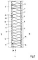
- Fig. 2 a horizontal section through the wall 1 is shown.
- the structure of the intermediate layer 4 can be seen here consists of a carrier material 7 on the strip-like Strips 9 are applied.
- the strips 9 are with a certain distance from one another in parallel on the carrier material 7 applied, which forms the space between the individual strips a channel 10.
- the channel is provided with Dimensions from 0.5 to 2.0 cm in height and 1.0 to 7.0 cm to design in width.
- An elastic material is, for example, the carrier material 7 provided so that the carrier material 7 against the Insulation layer 2 can be moved, as for example in the bulge 31 is shown.
- a line 32 in the duct has been installed, the diameter of the pipe 32 is greater than the depth of the channel 10. Due to the elastic Design of the carrier material 7, it is possible that the Channel 10 is widened locally, causing the retraction of the Line 32 is possible. Accordingly, this area the strip-like strips 9 are not on the boundary layer 3 on. This is a particular advantage of the invention that lines with diameters that are greater than the depth of the canal, also retrofitted in the walls can be.
- the intermediate layer 4 is in this way between the boundary layer 3 and the insulation layer 2 arranged that the Carrier material 7 of the insulation layer 2 and the strip-like Stripes 9 of the boundary layer 3 are inclined.
- the intermediate layer on the Frame glued or stapled.
- the outer planks 14 are, for example, directly on the frame 6 because of the disc formation of the building and the structural requirements.
- the intermediate layer 4 is continuous on the inside in FIG. 2 applied to the frame 6.
- the inner lining 15 is then attached to the frame 6, being between frame and Inner lining is also the intermediate layer 4.
- an adhesive bond is provided.
- the adhesive layer is designated 34.
- the strip-like strips 9 are through an adhesive layer 8 connected to the carrier material 7.
- an adhesive layer which makes the carrier material open to diffusion is.
- an adhesive layer 8 On the inside 12 is the carrier material 7 completely covered with an adhesive layer 8. This creates a vapor barrier or vapor barrier.
- Water glass for example, Casein, bone glue, wallpaper glue, corn starch, bitumen or Liguin into consideration.
- Other properties like fire protection, Insect resistance, fungus resistance or environmental compatibility by appropriate choice of the carrier material, the adhesive layer and the strip-like strips be influenced favorably.
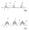
- FIG. 3 and 4 each show an embodiment of the intermediate layer 4 shown.
- Fig. 3 is a straight cardboard as a carrier material 7 provided, this has at constant intervals longitudinal adhesive layer 8 on which the strip-like Strips 9 are applied.
- the strip-like Strip 9 for example, as a single-row granulate 36 educated.
- strip-like Strips 9 are made of other materials, for example made of glued, elastic continuous material strips like plastic, etc. According to the invention Reference is made to the use of cork, which is stuck on as cork granulate becomes.
- Fig. 3 it is shown that the granules in one row (36) on the Carrier material 7 is applied.
- the carrier material 7 also has in the area of glued-on strip-like strips a roof-like bead 38 on by folding the carrier material 7, for example Cardboard, paper or laminated paper. It is e.g. it is also possible that multi-row granulate on a flat Carrier material is applied.
- the carrier material 7 In addition to the exemplary embodiments shown in FIGS. 3 and 4 further shapes are possible for the carrier material 7. It is possible, for example, as a carrier layer of corrugated cardboard with pointed, sinusoidal corrugated cardboard, trapezoidal cardboard or dovetail cardboard to use.
- the recesses formed by the pointed also fill up with granules.
- the cardboard e.g. also a corrugated cardboard
- the composite panel then forms the boundary layer.
- Plastic is no longer processed in the wall like it is was previously necessary for processing empty pipes.
- a great advantage achieved because only cellulosic materials like Paper, cardboard, cardboard, waste paper or wood, etc. is used will. It will thus make a huge contribution to environmental protection accomplished because of the materiality of the wall disposal or preparing the wall is no problem.
- Of the present invention further provides a versatile, unrestricted, immediately or later usable Installation duct, prepared at every point, available.
- the present invention also a cost advantage over the commonly used Empty pipes on.
- the invention is not only with external walls, but also with Interior walls and sloping walls applicable.
Landscapes
- Engineering & Computer Science (AREA)
- Architecture (AREA)
- Electromagnetism (AREA)
- Civil Engineering (AREA)
- Structural Engineering (AREA)
- Physics & Mathematics (AREA)
- Glass Compositions (AREA)
- Building Environments (AREA)
- Iron Core Of Rotating Electric Machines (AREA)
- Display Devices Of Pinball Game Machines (AREA)
- Thermally Insulated Containers For Foods (AREA)
- Panels For Use In Building Construction (AREA)
- Installation Of Indoor Wiring (AREA)
Applications Claiming Priority (2)
| Application Number | Priority Date | Filing Date | Title |
|---|---|---|---|
| DE4332593 | 1993-09-24 | ||
| DE4332593A DE4332593A1 (de) | 1993-09-24 | 1993-09-24 | Wand |
Publications (3)
| Publication Number | Publication Date |
|---|---|
| EP0645503A2 EP0645503A2 (de) | 1995-03-29 |
| EP0645503A3 EP0645503A3 (de) | 1995-10-18 |
| EP0645503B1 true EP0645503B1 (de) | 1998-06-03 |
Family
ID=6498561
Family Applications (1)
| Application Number | Title | Priority Date | Filing Date |
|---|---|---|---|
| EP94114685A Expired - Lifetime EP0645503B1 (de) | 1993-09-24 | 1994-09-17 | Wand |
Country Status (7)
| Country | Link |
|---|---|
| EP (1) | EP0645503B1 (da) |
| AT (1) | ATE166939T1 (da) |
| DE (2) | DE4332593A1 (da) |
| DK (1) | DK0645503T3 (da) |
| ES (1) | ES2117746T3 (da) |
| FI (1) | FI944388A7 (da) |
| NO (1) | NO312557B1 (da) |
Families Citing this family (6)
| Publication number | Priority date | Publication date | Assignee | Title |
|---|---|---|---|---|
| DE19750668C2 (de) * | 1997-11-15 | 2001-05-03 | Lothar Beer | Fertigbauteil als tragendes Element zur Befestigung von Bauteilen |
| DE19963360C2 (de) * | 1999-02-03 | 2003-08-21 | Jochen Leserer | Verfahren zur Errichtung von Bauwerken mit niedrigen K-Werten |
| DE10005155A1 (de) * | 2000-02-07 | 2001-08-23 | Oekologische Bausysteme B I Mo | Versorgungskanal für Wände mit Dampfsperre |
| DE202006014865U1 (de) * | 2006-09-22 | 2008-02-07 | Schmidler, Richard | Wandelement im Holzrahmenbau |
| DE102006045326A1 (de) * | 2006-09-22 | 2008-04-03 | Richard Schmidler | Wand-Beplankung im Holzrahmenbau |
| AT13558U1 (de) * | 2013-02-04 | 2014-03-15 | Baumeister Ing Juergen Hoeller Gmbh | Anschlussaufbau einer lasttragenden Strohballenwand an eine Bodenplatte |
Family Cites Families (5)
| Publication number | Priority date | Publication date | Assignee | Title |
|---|---|---|---|---|
| US3318056A (en) * | 1957-03-25 | 1967-05-09 | Cue Thompson & Company | Ventilating wall construction with stud location indicators |
| DE1534694B1 (de) * | 1966-08-10 | 1970-01-22 | Asbestzement Ind Gmbh Karl Ado | Bauwerkswand mit einem tragenden Gerippe und Wandschalen aus Faserzementplatten sowie Montageeinheit zur Herstellung derselben |
| US4488390A (en) * | 1982-04-26 | 1984-12-18 | Mulford Cass F | Structural building members and wall incorporating same |
| DE3217072A1 (de) * | 1982-05-06 | 1983-11-10 | Gotthard 8359 Ortenburg Sonnleitner | Holzblockhaus |
| WO1992017657A1 (en) * | 1991-04-01 | 1992-10-15 | Walter Lindal | Wooden frame building construction |
-
1993
- 1993-09-24 DE DE4332593A patent/DE4332593A1/de not_active Withdrawn
-
1994
- 1994-08-19 NO NO19943061A patent/NO312557B1/no unknown
- 1994-09-17 EP EP94114685A patent/EP0645503B1/de not_active Expired - Lifetime
- 1994-09-17 DK DK94114685T patent/DK0645503T3/da active
- 1994-09-17 ES ES94114685T patent/ES2117746T3/es not_active Expired - Lifetime
- 1994-09-17 AT AT94114685T patent/ATE166939T1/de not_active IP Right Cessation
- 1994-09-17 DE DE59406122T patent/DE59406122D1/de not_active Expired - Fee Related
- 1994-09-22 FI FI944388A patent/FI944388A7/fi unknown
Also Published As
| Publication number | Publication date |
|---|---|
| FI944388A0 (fi) | 1994-09-22 |
| EP0645503A2 (de) | 1995-03-29 |
| EP0645503A3 (de) | 1995-10-18 |
| NO312557B1 (no) | 2002-05-27 |
| FI944388L (fi) | 1995-03-25 |
| DE4332593A1 (de) | 1995-03-30 |
| NO943061D0 (no) | 1994-08-19 |
| FI944388A7 (fi) | 1995-03-25 |
| DE59406122D1 (de) | 1998-07-09 |
| ES2117746T3 (es) | 1998-08-16 |
| NO943061L (no) | 1995-03-27 |
| DK0645503T3 (da) | 1999-03-22 |
| ATE166939T1 (de) | 1998-06-15 |
Similar Documents
| Publication | Publication Date | Title |
|---|---|---|
| EP0581269B1 (de) | Aussendämm- und Oberflächenbehandlungssystem | |
| DE69327398T2 (de) | Thermoplastisches struktursystem | |
| EP0645503B1 (de) | Wand | |
| DE3209091A1 (de) | Verbundplatte fuer eine fussbodenheizung | |
| DE19716516A1 (de) | Dämm-Dränelemente aus Kunststoffhartschaum und Verfahren für die Anwendung im Erdreich | |
| CH687884A5 (de) | Holzbautafel. | |
| DE102024115157A1 (de) | Bauwerksabdichtung an einem Bauwerk sowie Verfahren zum Abdichten eines Bauwerks | |
| DE9320234U1 (de) | Abdichtung gegen das Eindringen gefährlicher Gase, insbesondere Radon, aus dem Baugrund | |
| DE29510935U1 (de) | Wand | |
| DE9101883U1 (de) | Bauschutzplatte | |
| EP2479359B1 (de) | Schallschutzelement und Verfahren zum Fertigen eines Schallschutzelementes | |
| EP1992740B1 (de) | Schallschutzelement und Verfahren zu dessen Herstellung | |
| DE102008059364B4 (de) | Gebäude-Schalldämmmatte | |
| DE102007057478B4 (de) | Gebäude-Schalldämmmatte | |
| DE29618522U1 (de) | Bausatz für ein Fertigteilhaus | |
| DE4239004A1 (de) | Stegplatte zur Unterbodenkonstruktion | |
| DE4322745A1 (de) | Dachdämmplatte | |
| DE3318444A1 (de) | Aus einzelelementen bestehendes waerme- oder isolierdach | |
| DE3021537A1 (de) | Isolierung fuer den hoch- und tiefbau | |
| DE19604571C2 (de) | Formkörper für die Außendämmung von Bauwerken | |
| DE10030729A1 (de) | Plattenelement zur Erstellung von Wand,Decke oder Dach eines Bauwerks | |
| DE2043030A1 (en) | Insulation of house or building foundation - walls | |
| DE102014013420B4 (de) | Schichtholzplatte und Verfahren zu deren Herstellung | |
| DE19916247A1 (de) | Baukastensystem für Fertighäuser | |
| WO2010105835A2 (de) | Belagskonstruktion |
Legal Events
| Date | Code | Title | Description |
|---|---|---|---|
| PUAI | Public reference made under article 153(3) epc to a published international application that has entered the european phase |
Free format text: ORIGINAL CODE: 0009012 |
|
| AK | Designated contracting states |
Kind code of ref document: A2 Designated state(s): AT BE CH DE DK ES FR GB IE IT LI PT SE |
|
| PUAL | Search report despatched |
Free format text: ORIGINAL CODE: 0009013 |
|
| AK | Designated contracting states |
Kind code of ref document: A3 Designated state(s): AT BE CH DE DK ES FR GB IE IT LI PT SE |
|
| 17P | Request for examination filed |
Effective date: 19951118 |
|
| GRAG | Despatch of communication of intention to grant |
Free format text: ORIGINAL CODE: EPIDOS AGRA |
|
| GRAG | Despatch of communication of intention to grant |
Free format text: ORIGINAL CODE: EPIDOS AGRA |
|
| GRAH | Despatch of communication of intention to grant a patent |
Free format text: ORIGINAL CODE: EPIDOS IGRA |
|
| 17Q | First examination report despatched |
Effective date: 19971105 |
|
| GRAH | Despatch of communication of intention to grant a patent |
Free format text: ORIGINAL CODE: EPIDOS IGRA |
|
| GRAA | (expected) grant |
Free format text: ORIGINAL CODE: 0009210 |
|
| AK | Designated contracting states |
Kind code of ref document: B1 Designated state(s): AT BE CH DE DK ES FR GB IE IT LI PT SE |
|
| REF | Corresponds to: |
Ref document number: 166939 Country of ref document: AT Date of ref document: 19980615 Kind code of ref document: T |
|
| REG | Reference to a national code |
Ref country code: CH Ref legal event code: NV Representative=s name: PA ALDO ROEMPLER Ref country code: CH Ref legal event code: EP |
|
| GBT | Gb: translation of ep patent filed (gb section 77(6)(a)/1977) |
Effective date: 19980603 |
|
| REF | Corresponds to: |
Ref document number: 59406122 Country of ref document: DE Date of ref document: 19980709 |
|
| ET | Fr: translation filed | ||
| ITF | It: translation for a ep patent filed | ||
| REG | Reference to a national code |
Ref country code: ES Ref legal event code: FG2A Ref document number: 2117746 Country of ref document: ES Kind code of ref document: T3 |
|
| REG | Reference to a national code |
Ref country code: IE Ref legal event code: FG4D Free format text: GERMAN |
|
| REG | Reference to a national code |
Ref country code: PT Ref legal event code: SC4A Free format text: AVAILABILITY OF NATIONAL TRANSLATION Effective date: 19980630 |
|
| REG | Reference to a national code |
Ref country code: DK Ref legal event code: T3 |
|
| PLBE | No opposition filed within time limit |
Free format text: ORIGINAL CODE: 0009261 |
|
| STAA | Information on the status of an ep patent application or granted ep patent |
Free format text: STATUS: NO OPPOSITION FILED WITHIN TIME LIMIT |
|
| 26N | No opposition filed | ||
| PGFP | Annual fee paid to national office [announced via postgrant information from national office to epo] |
Ref country code: GB Payment date: 20000908 Year of fee payment: 7 |
|
| PGFP | Annual fee paid to national office [announced via postgrant information from national office to epo] |
Ref country code: FR Payment date: 20000918 Year of fee payment: 7 |
|
| PGFP | Annual fee paid to national office [announced via postgrant information from national office to epo] |
Ref country code: ES Payment date: 20000922 Year of fee payment: 7 Ref country code: DK Payment date: 20000922 Year of fee payment: 7 Ref country code: BE Payment date: 20000922 Year of fee payment: 7 |
|
| PGFP | Annual fee paid to national office [announced via postgrant information from national office to epo] |
Ref country code: SE Payment date: 20000928 Year of fee payment: 7 |
|
| PGFP | Annual fee paid to national office [announced via postgrant information from national office to epo] |
Ref country code: IE Payment date: 20001006 Year of fee payment: 7 |
|
| PGFP | Annual fee paid to national office [announced via postgrant information from national office to epo] |
Ref country code: PT Payment date: 20001013 Year of fee payment: 7 |
|
| PGFP | Annual fee paid to national office [announced via postgrant information from national office to epo] |
Ref country code: CH Payment date: 20001212 Year of fee payment: 7 |
|
| PG25 | Lapsed in a contracting state [announced via postgrant information from national office to epo] |
Ref country code: IE Free format text: LAPSE BECAUSE OF NON-PAYMENT OF DUE FEES Effective date: 20010917 Ref country code: GB Free format text: LAPSE BECAUSE OF NON-PAYMENT OF DUE FEES Effective date: 20010917 Ref country code: DK Free format text: LAPSE BECAUSE OF NON-PAYMENT OF DUE FEES Effective date: 20010917 |
|
| PG25 | Lapsed in a contracting state [announced via postgrant information from national office to epo] |
Ref country code: SE Free format text: LAPSE BECAUSE OF NON-PAYMENT OF DUE FEES Effective date: 20010918 Ref country code: ES Free format text: LAPSE BECAUSE OF NON-PAYMENT OF DUE FEES Effective date: 20010918 |
|
| PG25 | Lapsed in a contracting state [announced via postgrant information from national office to epo] |
Ref country code: LI Free format text: LAPSE BECAUSE OF NON-PAYMENT OF DUE FEES Effective date: 20010930 Ref country code: CH Free format text: LAPSE BECAUSE OF NON-PAYMENT OF DUE FEES Effective date: 20010930 Ref country code: BE Free format text: LAPSE BECAUSE OF NON-PAYMENT OF DUE FEES Effective date: 20010930 |
|
| REG | Reference to a national code |
Ref country code: GB Ref legal event code: IF02 |
|
| BERE | Be: lapsed |
Owner name: FRITZ HUBERT Effective date: 20010930 |
|
| PG25 | Lapsed in a contracting state [announced via postgrant information from national office to epo] |
Ref country code: PT Free format text: LAPSE BECAUSE OF NON-PAYMENT OF DUE FEES Effective date: 20020331 |
|
| EUG | Se: european patent has lapsed |
Ref document number: 94114685.4 |
|
| GBPC | Gb: european patent ceased through non-payment of renewal fee |
Effective date: 20010917 |
|
| REG | Reference to a national code |
Ref country code: CH Ref legal event code: PL |
|
| PG25 | Lapsed in a contracting state [announced via postgrant information from national office to epo] |
Ref country code: FR Free format text: LAPSE BECAUSE OF NON-PAYMENT OF DUE FEES Effective date: 20020531 |
|
| REG | Reference to a national code |
Ref country code: DK Ref legal event code: EBP |
|
| REG | Reference to a national code |
Ref country code: FR Ref legal event code: ST |
|
| REG | Reference to a national code |
Ref country code: IE Ref legal event code: MM4A |
|
| REG | Reference to a national code |
Ref country code: PT Ref legal event code: MM4A Free format text: LAPSE DUE TO NON-PAYMENT OF FEES Effective date: 20020331 |
|
| PGFP | Annual fee paid to national office [announced via postgrant information from national office to epo] |
Ref country code: AT Payment date: 20020906 Year of fee payment: 9 |
|
| PG25 | Lapsed in a contracting state [announced via postgrant information from national office to epo] |
Ref country code: AT Free format text: LAPSE BECAUSE OF NON-PAYMENT OF DUE FEES Effective date: 20030917 |
|
| REG | Reference to a national code |
Ref country code: ES Ref legal event code: FD2A Effective date: 20021011 |
|
| PG25 | Lapsed in a contracting state [announced via postgrant information from national office to epo] |
Ref country code: IT Free format text: LAPSE BECAUSE OF NON-PAYMENT OF DUE FEES;WARNING: LAPSES OF ITALIAN PATENTS WITH EFFECTIVE DATE BEFORE 2007 MAY HAVE OCCURRED AT ANY TIME BEFORE 2007. THE CORRECT EFFECTIVE DATE MAY BE DIFFERENT FROM THE ONE RECORDED. Effective date: 20050917 |
|
| PGFP | Annual fee paid to national office [announced via postgrant information from national office to epo] |
Ref country code: DE Payment date: 20051122 Year of fee payment: 12 |
|
| PG25 | Lapsed in a contracting state [announced via postgrant information from national office to epo] |
Ref country code: DE Free format text: LAPSE BECAUSE OF NON-PAYMENT OF DUE FEES Effective date: 20070403 |