EP0641977A1 - Aménagement de salle blanche - Google Patents
Aménagement de salle blanche Download PDFInfo
- Publication number
- EP0641977A1 EP0641977A1 EP94113182A EP94113182A EP0641977A1 EP 0641977 A1 EP0641977 A1 EP 0641977A1 EP 94113182 A EP94113182 A EP 94113182A EP 94113182 A EP94113182 A EP 94113182A EP 0641977 A1 EP0641977 A1 EP 0641977A1
- Authority
- EP
- European Patent Office
- Prior art keywords
- clean room
- room system
- clean
- plates
- axial fan
- Prior art date
- Legal status (The legal status is an assumption and is not a legal conclusion. Google has not performed a legal analysis and makes no representation as to the accuracy of the status listed.)
- Granted
Links
Images

Classifications
-
- F—MECHANICAL ENGINEERING; LIGHTING; HEATING; WEAPONS; BLASTING
- F24—HEATING; RANGES; VENTILATING
- F24F—AIR-CONDITIONING; AIR-HUMIDIFICATION; VENTILATION; USE OF AIR CURRENTS FOR SCREENING
- F24F3/00—Air-conditioning systems in which conditioned primary air is supplied from one or more central stations to distributing units in the rooms or spaces where it may receive secondary treatment; Apparatus specially designed for such systems
- F24F3/12—Air-conditioning systems in which conditioned primary air is supplied from one or more central stations to distributing units in the rooms or spaces where it may receive secondary treatment; Apparatus specially designed for such systems characterised by the treatment of the air otherwise than by heating and cooling
- F24F3/16—Air-conditioning systems in which conditioned primary air is supplied from one or more central stations to distributing units in the rooms or spaces where it may receive secondary treatment; Apparatus specially designed for such systems characterised by the treatment of the air otherwise than by heating and cooling by purification, e.g. by filtering; by sterilisation; by ozonisation
- F24F3/167—Clean rooms, i.e. enclosed spaces in which a uniform flow of filtered air is distributed
-
- F—MECHANICAL ENGINEERING; LIGHTING; HEATING; WEAPONS; BLASTING
- F24—HEATING; RANGES; VENTILATING
- F24F—AIR-CONDITIONING; AIR-HUMIDIFICATION; VENTILATION; USE OF AIR CURRENTS FOR SCREENING
- F24F3/00—Air-conditioning systems in which conditioned primary air is supplied from one or more central stations to distributing units in the rooms or spaces where it may receive secondary treatment; Apparatus specially designed for such systems
-
- B—PERFORMING OPERATIONS; TRANSPORTING
- B29—WORKING OF PLASTICS; WORKING OF SUBSTANCES IN A PLASTIC STATE IN GENERAL
- B29C—SHAPING OR JOINING OF PLASTICS; SHAPING OF MATERIAL IN A PLASTIC STATE, NOT OTHERWISE PROVIDED FOR; AFTER-TREATMENT OF THE SHAPED PRODUCTS, e.g. REPAIRING
- B29C48/00—Extrusion moulding, i.e. expressing the moulding material through a die or nozzle which imparts the desired form; Apparatus therefor
- B29C48/14—Extrusion moulding, i.e. expressing the moulding material through a die or nozzle which imparts the desired form; Apparatus therefor characterised by the particular extruding conditions, e.g. in a modified atmosphere or by using vibration
- B29C48/141—Extrusion moulding, i.e. expressing the moulding material through a die or nozzle which imparts the desired form; Apparatus therefor characterised by the particular extruding conditions, e.g. in a modified atmosphere or by using vibration extruding in a clean room
-
- B—PERFORMING OPERATIONS; TRANSPORTING
- B29—WORKING OF PLASTICS; WORKING OF SUBSTANCES IN A PLASTIC STATE IN GENERAL
- B29C—SHAPING OR JOINING OF PLASTICS; SHAPING OF MATERIAL IN A PLASTIC STATE, NOT OTHERWISE PROVIDED FOR; AFTER-TREATMENT OF THE SHAPED PRODUCTS, e.g. REPAIRING
- B29C2791/00—Shaping characteristics in general
- B29C2791/004—Shaping under special conditions
- B29C2791/005—Using a particular environment, e.g. sterile fluids other than air
-
- Y—GENERAL TAGGING OF NEW TECHNOLOGICAL DEVELOPMENTS; GENERAL TAGGING OF CROSS-SECTIONAL TECHNOLOGIES SPANNING OVER SEVERAL SECTIONS OF THE IPC; TECHNICAL SUBJECTS COVERED BY FORMER USPC CROSS-REFERENCE ART COLLECTIONS [XRACs] AND DIGESTS
- Y10—TECHNICAL SUBJECTS COVERED BY FORMER USPC
- Y10S—TECHNICAL SUBJECTS COVERED BY FORMER USPC CROSS-REFERENCE ART COLLECTIONS [XRACs] AND DIGESTS
- Y10S454/00—Ventilation
- Y10S454/906—Noise inhibiting means
Definitions
- the invention relates to a clean room system according to the preamble of claim 1.
- the clean air escaping through the floor of the clean room is passed through a prefilter, a flap device connected to it, a heat exchanger and a backdrop silencer before it reaches the blower, which is preferably designed as an axial fan.
- Another link silencer is arranged on the pressure side. Because of this arrangement, a high pressure loss occurs during operation.
- the axial fan is therefore designed as a medium or high-pressure fan with high passage speeds. Therefore, the fan is additionally followed by a relatively long diffuser, by at least part to recover the high dynamic pressure component in usable static pressure.
- the pressure loss in the prefilter is in the order of about 150 to 180 Pa. Pressure losses of a similar magnitude are caused by the two link silencers.
- the static pressure loss of the system to be overcome by the fan typically reaches values of approx. 500 to 700 Pa.
- in particular axial fans are used which, due to their design, have a high dynamic pressure component of approximately 300 to 400 Pa, which can also only be partially recovered in usable static pressure by means of a downstream diffuser.
- this known construction also leads to high operating costs. It is therefore not possible to work inexpensively with this known clean room system.
- the invention has for its object to design the generic clean room system so that the pressure losses during operation can be kept low, so that the clean room system can be used to save costs.
- the clean air emerging from the clean room preferably flows unfiltered to the blower. No pre-filter is then necessary in the flow area between the clean room and the fan. Likewise, there is no arrangement of link silencers on the pressure and suction side. This will make the In the flow area of the system, pressure losses caused by internals are considerably reduced. Due to these very low pressure losses, which essentially only arise from the suspended matter filters in the ceiling area of the clean room, axial fans designed for low pressure with a large flow cross section and thus only a small dynamic pressure component of approx. 20 to 70 Pa are sufficient for air circulation, i.e. even without a downstream diffuser additional energy consumption caused by the dynamic pressure component is very small.
- the static differential pressure to be overcome by the fan drops to approximately 120 to 250 Pa in the case of a vertical displacement flow in the clean room of approximately 0.45 m / s due to the arrangement according to the invention.
- the axial fans designed for low pressure can be used up to a static pressure difference of about 300 Pa. Fans of this type are extremely inexpensive and have only a comparatively low noise level. The sound level in the clean room can therefore be kept at a low level with simple measures according to the invention while avoiding the usual complex backdrop silencer.
- the clean room system according to the invention is thus distinguished by considerably lower investment and operating costs.
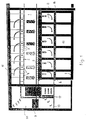
- FIG. 1 shows in cross section a clean room system which has at least one clean room 1.
- a clean air stream flows vertically through it.
- the ceiling 2 of the clean room 1 is formed by adjacent filter units 3, which are arranged one behind the other and next to one another and are formed in a known manner and through which the clean air flows down into the clean room 1.
- the filter units 3 are arranged and held in a known manner in a grid-like manner in the ceiling area of the clean room 1.
- the clean room 1 has a raised floor 5, through which the clean air flows down out of the clean room 1.
- the raised floor 5 is supported on a foundation 7 via supports 6.
- the clean room 1 is evenly flowed through by clean air, which at the bottom reaches the return space 8 via the raised floor 5, from which the clean air is sucked in by at least one axial fan 9. It is accommodated in a side room 10 which is sealed off from the clean room 1.
- the intake of clean air is, like the flow arrows in 1 show, conveyed into an inflow space 11, which is located in the area above the filter units 3. From there, the clean air returns to the individual filter units 3. In the manner described, the clean air is circulated within the clean room system.
- the axial fan 9 is preceded only by a flow flap device 12 which extends over the entire height and length of the flow path of the clean air within the adjoining room 10.
- the flow flap device 12 is required in order to be able to switch off individual fan areas in the case of a plurality of fans arranged in the longitudinal direction of the building in such a way that no air flows to the suction side in the opposite direction to the original flow.
- the flow flap device 12 which is fully open when the fan is in operation is seated on a floor 13 which is arranged at a distance above the foundation 7.
- a plurality of axial fans 9 are arranged next to or behind one another at a distance. This ensures that the clean air is supplied over the entire width or length to the inflow space 11 above the filter units 3.
- the inflow space 11 can be so high that it can be walked on, for example in order to be able to carry out repair or maintenance work on the filter units 3.
- the axial fans 9 are characterized by the fact that they have large flow cross sections and thus only low flow velocities in the order of magnitude of about 6 to 11 m / s, are inexpensive to purchase and, because of the low flow velocities, have only small dynamic pressure components and are very high make little noise. Therefore, no or only minor additional noise reduction measures are required.
- the clean room system according to FIG. 1 is characterized by a structurally simple and accordingly also very inexpensive design because of the very low pressure losses.
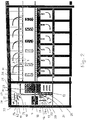
- FIG. 2 shows a clean room system which differs from the exemplary embodiment according to FIG. 1 only in the arrangement of silencers 16 and 17 in front of and behind the axial fans 9. Both silencers 16, 17 are housed in the adjoining room 10. As in the previous embodiment, the axial fans 9 are arranged in a false ceiling 18 which divides the adjoining room 10. The axial fans 9 can be easily mounted in the false ceiling 18.
- the muffler 16 in the suction area of the axial fan 9 is formed by plates 19 to 21 which are spaced apart and which advantageously extend over the entire length of the adjoining room 10.
- These plates 19 to 21 consist of any suitable sound-absorbing material, preferably of outgassing-free material or are covered with sound-absorbing material.
- membrane absorbers can also be used as silencers 16.
- the plates 19 to 21 have different lengths in the flow direction of the clean air.
- the plate 21 closest to the flow flap device 12 has the smallest length of the three plates.
- the adjacent muffler plate 20 is longer than the plate 21, but shorter than the plate 19. The distance between the muffler plates 21 and 20 is less than the distance between the muffler plates 20 and 19.
- the length gradation, the thickness of the plates and the different distances between them The muffler plates 19 to 21 are selected so that a uniform suction of the clean air and a uniform sound attenuation is achieved via the suction area of the axial fan 9.
- the silencer plates 19 to 21 are parallel to each other and each extend in the vertical direction. The ends of the plates 19 to 21 facing the axial fan 9 are at the same height. These panels are not only used for sound insulation, but also for the flow of clean air. This ensures that the clean air can be optimally sucked in by the axial fans 9.
- a flow channel 22 and 23 is formed between the silencer plates 19, 20 and 20, 21.
- flow channels 24 and 25 are formed between the plate 19 and the adjacent side wall 26 of the adjoining room 10 and between the plate 21 and an adjacent wall 27 in the adjoining room 10.
- the clean air flowing in at least approximately horizontally via the flow flap device 12 is deflected at a right angle after passing through and flows through the flow channels 22 to 25 to the axial fans 9 in a uniform distribution.
- the muffler 17 in the flow area behind the axial fans 9 serves not only for sound absorption, but also as a flow control device for the clean air.
- the muffler 17 is formed by three mutually parallel sound insulation panels 28 to 30, which have different lengths in the direction of flow of the clean air.
- the distance between the plates 28 and 29 is greater than the distance between the plates 29 and 30.
- a flow channel 32 is formed between the plate 28 and the adjacent ceiling 31 of the inflow space 11.
- Another flow channel 33 is formed by the plates 28 and 29.
- the plates 29 and 30 delimit a third flow channel 42.
- a fourth flow channel 34 is formed between the plate 30 and an adjacent wall 35 in the adjoining room 10.
- the plate 30 lying parallel to the wall 35 has the smallest length, while the plate 28 lying adjacent to the ceiling 31 has the greatest length.
- the length of the plates 28 to 30, their thickness and their distance from each other and from the ceiling 31 and the wall 35 is again chosen so that the clean air flows into the inflow space 11 in a uniform flow distribution and uniform sound damping is achieved.
- the ends of the plates 28 to 30 facing the inflow space 11 are at the same height.
- the soundproofing plates 28 to 30 can in turn consist of any suitable sound-absorbing material, preferably of outgassing-free material, or can be coated with a corresponding material. 2 shows, the plates 28 to 30 are horizontal and thus at right angles to the plates 19 to 21 of the silencer 16. The clean air is deflected at right angles to the silencer plates 28 to 30.
- the ceiling 31 of the clean room system lies approximately at right angles to the outflow direction of the axial fans 9. This has the advantage that part of the sound is reflected on the ceiling 31 back to the axial fans 9 and not in the direction of the clean room 1 . This results in additional noise reduction.
- the plates 28 to 30 of the muffler 17 can extend in the horizontal direction even further in the direction of the flow space 11, so that greater sound absorption is achieved.
- the plates 28 to 30 in turn extend over the entire width of the adjoining room 10. They are at a distance from the vertical side wall 26 of the clean room system.
- the embodiment according to FIG. 2 is also characterized by a simple construction. It works very quietly and has only very low pressure losses, which - as in the exemplary embodiment according to FIG. 1 - are essentially only generated by the suspended matter filter 4 of the filter-fan units 3. Because of the low pressure losses, as in the previous exemplary embodiment, the axial fans 9 are sufficient to convey the clean air. The axial fans 9 run very quietly, so that little or no additional noise reduction measures are required. In addition, the axial fans 9 have only a small axial length, so that they require little installation space. The embodiment according to FIG. 2 also only causes relatively low operating costs and also requires little energy. That is why this clean room system can be used inexpensively.
- the silencer 16 in the suction area of the axial fan 9 can be dispensed with. In this case, only the silencer 17 is provided in the flow area behind the axial fans 9. Such a clean room system is even less expensive to manufacture than the exemplary embodiment according to FIG. 2.
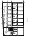
- FIG. 3 is essentially the same as the embodiment of FIG. 2. The only difference is that the side walls of the adjoining room 10 of the clean room system are covered with soundproofing material, whereby extremely high soundproofing is achieved.
- the floor 13 of the adjoining room 10 is covered with sound-absorbing material 36 in the area between the flow flap device 12 and the vertical side wall 26.
- the side wall 26 is also provided in the region between the covering 36 and the axial fans 9 with a sound-absorbing covering 37.
- the side wall 26 is provided with a further sound-absorbing covering 38.
- the ceiling 31 also has a sound-absorbing covering 40 in the area between the covering 38 and a vertical wall 39 separating the clean room 1 from the adjoining room 10.
- the wall 39 forms the boundary wall of the adjoining room 10 opposite the side wall 26, which extends from the ceiling 31 to the foundation 7 of the clean room system.
- the wall 39 is provided with corresponding openings.
- the wall 27 lying at a distance from the side wall 26 and running parallel to it is provided in the adjoining room 10 with a sound-insulating covering 41.
- This covering extends from the false ceiling 18 over the entire height and width of the wall 27.
- the wall 27 is connected at a right angle to the wall 35 at a distance from the ceiling 31, which wall likewise has a sound-absorbing covering 43 is.
- the axial fans 9 are provided at one end of the clean room system.
- a corresponding side room with axial fans and possibly silencers on the opposite side wall of the clean room system.
- the clean room system can have more than one clean room 1.
- the silencers 16 and 17 can also have only two or more than three plates, depending on the existing installation conditions.
- FIG. 4 shows an embodiment of a clean room system in which the ceiling 31 is provided with a sound-absorbing covering 44 in the area of the inflow space 11.
- This covering 44 can in turn consist of any suitable sound-absorbing material.
- the ceiling 31 with one or be provided with several membrane absorbers, which can also be used as sound absorption parts.
- the ceiling 31 is advantageously provided with the covering 44 in the area of the inflow space 11 over the entire surface. It ensures optimal sound absorption, so that only a very low level of noise occurs in the clean room 1 underneath.
- the soundproofing parts can also be arranged suspended from the ceiling 31 in the inflow space 11. This also achieves excellent sound absorption. Clearances can be provided between individual or all sound-absorbing parts for the passage of the clean air. Otherwise, the exemplary embodiment is of the same design as the embodiment according to FIG. 3.
- the clean room system can also be designed in accordance with FIGS. 1 and 2.
- the clean room system can also have any other suitable design. It is only essential that the ceiling 31 of the inflow space 11, the so-called plenum, is covered with sound-absorbing parts or provided with membrane absorbers, so that very high sound insulation is achieved in the area of the plenum.
Landscapes
- Engineering & Computer Science (AREA)
- Mechanical Engineering (AREA)
- Chemical & Material Sciences (AREA)
- Combustion & Propulsion (AREA)
- General Engineering & Computer Science (AREA)
- Ventilation (AREA)
Applications Claiming Priority (2)
| Application Number | Priority Date | Filing Date | Title |
|---|---|---|---|
| DE4328995A DE4328995C2 (de) | 1993-08-28 | 1993-08-28 | Reinraumanlage |
| DE4328995 | 1993-08-28 |
Publications (2)
| Publication Number | Publication Date |
|---|---|
| EP0641977A1 true EP0641977A1 (fr) | 1995-03-08 |
| EP0641977B1 EP0641977B1 (fr) | 1998-04-01 |
Family
ID=6496261
Family Applications (1)
| Application Number | Title | Priority Date | Filing Date |
|---|---|---|---|
| EP94113182A Expired - Lifetime EP0641977B1 (fr) | 1993-08-28 | 1994-08-24 | Aménagement de salle blanche |
Country Status (6)
| Country | Link |
|---|---|
| US (1) | US5518451A (fr) |
| EP (1) | EP0641977B1 (fr) |
| KR (1) | KR100326609B1 (fr) |
| DE (2) | DE4328995C2 (fr) |
| ES (1) | ES2115120T3 (fr) |
| TW (1) | TW298611B (fr) |
Families Citing this family (24)
| Publication number | Priority date | Publication date | Assignee | Title |
|---|---|---|---|---|
| KR100252215B1 (ko) * | 1997-05-02 | 2000-04-15 | 윤종용 | 클린룸 계측장치 상태 모니터링 시스템 및 그를 이용한 모니터링 방법 |
| MXPA01010895A (es) | 1999-04-28 | 2003-06-24 | Stratotech Corp | Ambiente ajustable de flujo de aire limpio. |
| US7083515B2 (en) * | 1999-09-07 | 2006-08-01 | Speedfam-Ipec Corporation | Clean room facility and construction method |
| US6574937B1 (en) * | 1999-09-07 | 2003-06-10 | Speedfam-Ipec Corporation | Clean room and method |
| US11024527B2 (en) | 2005-06-18 | 2021-06-01 | Frederick A. Flitsch | Methods and apparatus for novel fabricators with Cleanspace |
| US7513822B2 (en) * | 2005-06-18 | 2009-04-07 | Flitsch Frederick A | Method and apparatus for a cleanspace fabricator |
| US10651063B2 (en) | 2005-06-18 | 2020-05-12 | Frederick A. Flitsch | Methods of prototyping and manufacturing with cleanspace fabricators |
| US10627809B2 (en) | 2005-06-18 | 2020-04-21 | Frederick A. Flitsch | Multilevel fabricators |
| US9339900B2 (en) * | 2005-08-18 | 2016-05-17 | Futrfab, Inc. | Apparatus to support a cleanspace fabricator |
| US9059227B2 (en) | 2005-06-18 | 2015-06-16 | Futrfab, Inc. | Methods and apparatus for vertically orienting substrate processing tools in a clean space |
| US9457442B2 (en) * | 2005-06-18 | 2016-10-04 | Futrfab, Inc. | Method and apparatus to support process tool modules in a cleanspace fabricator |
| US9159592B2 (en) | 2005-06-18 | 2015-10-13 | Futrfab, Inc. | Method and apparatus for an automated tool handling system for a multilevel cleanspace fabricator |
| US7467024B2 (en) * | 2005-08-26 | 2008-12-16 | Flitsch Frederick A | Method and apparatus for an elevator system for a multilevel cleanspace fabricator |
| CN105304529B (zh) | 2005-09-18 | 2019-03-15 | 弗雷德里克·A·弗里奇 | 用于在洁净空间中垂直定位基片处理设备的方法和装置 |
| KR100650987B1 (ko) * | 2005-10-18 | 2006-11-29 | 김재성 | 저소음형 공조 패키지 및 이를 이용한 수술실 공조 시스템 |
| KR100789484B1 (ko) * | 2006-04-25 | 2008-01-02 | 김재성 | 저소음형 공조 패키지 및 이를 이용한 수술실 공조 시스템 |
| US7779960B2 (en) * | 2006-08-18 | 2010-08-24 | Hewlett-Packard Development Company, L.P. | System and method for noise suppression |
| FR2914400B1 (fr) * | 2007-03-30 | 2009-06-26 | Data 4 Soc Par Actions Simplif | Systeme de climatisation d'une piece |
| US9435552B2 (en) * | 2007-12-14 | 2016-09-06 | Ge-Hitachi Nuclear Energy Americas Llc | Air filtration and handling for nuclear reactor habitability area |
| US8087492B2 (en) * | 2010-03-08 | 2012-01-03 | Huntair, Inc. | Methods and systems for integrating sound attenuation into a filter bank |
| JP5427833B2 (ja) * | 2011-05-18 | 2014-02-26 | パナソニック株式会社 | クリーンルームの逆流防止装置 |
| DE202012100465U1 (de) * | 2012-02-10 | 2012-03-14 | Daldrop + Dr. Ing. Huber Gmbh & Co. Kg | Lüftungsgerät für Reinraumanwendungen |
| US9631825B2 (en) | 2012-12-18 | 2017-04-25 | Nortek Air Solutions, Llc | Air filter assembly |
| CN111457530A (zh) * | 2020-04-01 | 2020-07-28 | 北京联合大学 | 洁净室内移动污染源污染气隐藏式快速清除系统 |
Citations (3)
| Publication number | Priority date | Publication date | Assignee | Title |
|---|---|---|---|---|
| US4549472A (en) * | 1983-09-29 | 1985-10-29 | Hitachi Ltd. | Rearrangeable partial environmental control device |
| US4860420A (en) * | 1987-04-07 | 1989-08-29 | Flanders Filters, Inc. | Method of fabricating a clean room filter bank |
| DE3832915A1 (de) * | 1988-09-28 | 1990-03-29 | Martin Gabler | Reinraum |
Family Cites Families (13)
| Publication number | Priority date | Publication date | Assignee | Title |
|---|---|---|---|---|
| US3125286A (en) * | 1964-03-17 | sanders | ||
| US1916908A (en) * | 1929-06-04 | 1933-07-04 | Carrier Engineering Corp | Sound absorbing means |
| US1964845A (en) * | 1933-09-14 | 1934-07-03 | American Telephone & Telegraph | Ventilator |
| US2112608A (en) * | 1936-05-20 | 1938-03-29 | Westinghouse Electric & Mfg Co | Sound absorbing structure |
| US2270825A (en) * | 1939-12-12 | 1942-01-20 | Johns Manville | Sound-absorbing structure |
| US3975995A (en) * | 1975-03-13 | 1976-08-24 | American Air Filter Company, Inc. | Ventilated ceiling construction |
| DE2920278C2 (de) * | 1979-05-18 | 1984-01-12 | Aktiengesellschaft Kühnle, Kopp & Kausch, 6710 Frankenthal | Schalldämpfungseinrichtung |
| JPS625031A (ja) * | 1985-06-28 | 1987-01-12 | Kajima Corp | 部分的に清浄度の異なるクリ−ンル−ム |
| US4608066A (en) * | 1985-07-31 | 1986-08-26 | Flanders Filters, Inc. | Clean room adapted for variable work area configurations |
| US4747341A (en) * | 1986-11-19 | 1988-05-31 | Donaldson Company, Inc. | Integral grid structure for providing negative pressure plenum |
| JPH0650193B2 (ja) * | 1988-12-01 | 1994-06-29 | 日立プラント建設株式会社 | クリーンルームの床下ダクト構造 |
| JP2517112B2 (ja) * | 1989-06-21 | 1996-07-24 | 松下電器産業株式会社 | クリ―ントンネル |
| JP2574573B2 (ja) * | 1991-10-18 | 1997-01-22 | 松下精工株式会社 | 換気扇 |
-
1993
- 1993-08-28 DE DE4328995A patent/DE4328995C2/de not_active Expired - Fee Related
-
1994
- 1994-08-24 DE DE59405568T patent/DE59405568D1/de not_active Expired - Fee Related
- 1994-08-24 ES ES94113182T patent/ES2115120T3/es not_active Expired - Lifetime
- 1994-08-24 EP EP94113182A patent/EP0641977B1/fr not_active Expired - Lifetime
- 1994-08-26 TW TW083107839A patent/TW298611B/zh active
- 1994-08-26 US US08/297,444 patent/US5518451A/en not_active Expired - Fee Related
- 1994-08-29 KR KR1019940021345A patent/KR100326609B1/ko not_active IP Right Cessation
Patent Citations (3)
| Publication number | Priority date | Publication date | Assignee | Title |
|---|---|---|---|---|
| US4549472A (en) * | 1983-09-29 | 1985-10-29 | Hitachi Ltd. | Rearrangeable partial environmental control device |
| US4860420A (en) * | 1987-04-07 | 1989-08-29 | Flanders Filters, Inc. | Method of fabricating a clean room filter bank |
| DE3832915A1 (de) * | 1988-09-28 | 1990-03-29 | Martin Gabler | Reinraum |
Also Published As
| Publication number | Publication date |
|---|---|
| TW298611B (fr) | 1997-02-21 |
| US5518451A (en) | 1996-05-21 |
| KR100326609B1 (ko) | 2002-08-27 |
| KR950006370A (ko) | 1995-03-20 |
| EP0641977B1 (fr) | 1998-04-01 |
| DE4328995A1 (de) | 1995-03-02 |
| DE59405568D1 (de) | 1998-05-07 |
| DE4328995C2 (de) | 1997-01-23 |
| ES2115120T3 (es) | 1998-06-16 |
Similar Documents
| Publication | Publication Date | Title |
|---|---|---|
| EP0641977B1 (fr) | Aménagement de salle blanche | |
| DE4122582C2 (de) | Modul zum Aufbau einer Reinraumdecke | |
| EP0497296B1 (fr) | Installation de filtre-ventilateur pour l'utilisation dans des salles blanches | |
| EP0532874B1 (fr) | Conditionneur d'air pour le domaine humain | |
| EP0418511B1 (fr) | Appareil de conditionnement de l'air pour cabines d'ascenseurs à grande vitesse | |
| DE3006318C2 (de) | Lüftungsvorrichtung | |
| DE102008050546B4 (de) | Side-Feeder-Luftführungselement für eine Flugzeugklimaanlage | |
| DE2941276A1 (de) | Stroemungsverteilungsvorrichtung und ein mit einer solchen vorrichtung versehenes lufteintrittsgitter | |
| EP0735329B1 (fr) | Ventilateur pour salles propres | |
| DE102016226157A1 (de) | Ventilatormodul sowie Anordnung eines oder mehrerer solcher Ventilatormodule in einem Strömungskanal | |
| EP0340433A2 (fr) | Module de tunnel pour créer une enceinte propre en technique à flux laminaire | |
| DE2362013A1 (de) | Wirbelluftreinigeranordnung mit einer schalldaempfungseinrichtung | |
| DE4115171C2 (de) | Ventilator-Filtereinheit für Reinraumdecken | |
| DE4238595A1 (de) | Modulare Lüftungseinheit mit integriertem Ventilator und angeschlossenem Filterrahmen, insbesondere für reinraumtechnische Zwecke | |
| DE3401209C2 (fr) | ||
| DE4210279A1 (de) | Quelluftdurchlaß für raumlufttechnische Anlagen | |
| EP1496326A1 (fr) | Procédé et dispositif pour guider l'écoulement d'air dans un condenseur refroidi par air | |
| DE2135063A1 (de) | Vorrichtung zum klimatisieren von raeumen | |
| DE4103026C1 (fr) | ||
| DE4320162C2 (de) | Modul für eine Reinraumdecke | |
| WO2007107193A1 (fr) | Convecteur de sol | |
| EP0893655B1 (fr) | Unité de chauffage pour chauffage à air chaud pour églises | |
| DE69916087T2 (de) | Filter für ventilator mit hoher filterleistung, geringem energieverbrauch und geringer gräuschaussendung | |
| DE2841409A1 (de) | Luftauslass fuer klimaanlagen u.dgl. | |
| DE202015102781U1 (de) | Lüftungseinrichtung für Reinräume |
Legal Events
| Date | Code | Title | Description |
|---|---|---|---|
| PUAI | Public reference made under article 153(3) epc to a published international application that has entered the european phase |
Free format text: ORIGINAL CODE: 0009012 |
|
| AK | Designated contracting states |
Kind code of ref document: A1 Designated state(s): BE DE ES FR GB IE IT NL PT SE |
|
| 17P | Request for examination filed |
Effective date: 19950429 |
|
| 17Q | First examination report despatched |
Effective date: 19961024 |
|
| GRAG | Despatch of communication of intention to grant |
Free format text: ORIGINAL CODE: EPIDOS AGRA |
|
| GRAG | Despatch of communication of intention to grant |
Free format text: ORIGINAL CODE: EPIDOS AGRA |
|
| GRAH | Despatch of communication of intention to grant a patent |
Free format text: ORIGINAL CODE: EPIDOS IGRA |
|
| GRAH | Despatch of communication of intention to grant a patent |
Free format text: ORIGINAL CODE: EPIDOS IGRA |
|
| ITF | It: translation for a ep patent filed |
Owner name: INTERPATENT ST.TECN. BREV. |
|
| GRAA | (expected) grant |
Free format text: ORIGINAL CODE: 0009210 |
|
| AK | Designated contracting states |
Kind code of ref document: B1 Designated state(s): BE DE ES FR GB IE IT NL PT SE |
|
| GBT | Gb: translation of ep patent filed (gb section 77(6)(a)/1977) |
Effective date: 19980406 |
|
| REF | Corresponds to: |
Ref document number: 59405568 Country of ref document: DE Date of ref document: 19980507 |
|
| REG | Reference to a national code |
Ref country code: ES Ref legal event code: FG2A Ref document number: 2115120 Country of ref document: ES Kind code of ref document: T3 |
|
| PG25 | Lapsed in a contracting state [announced via postgrant information from national office to epo] |
Ref country code: PT Free format text: LAPSE BECAUSE OF FAILURE TO SUBMIT A TRANSLATION OF THE DESCRIPTION OR TO PAY THE FEE WITHIN THE PRESCRIBED TIME-LIMIT Effective date: 19980701 |
|
| ET | Fr: translation filed | ||
| REG | Reference to a national code |
Ref country code: IE Ref legal event code: FG4D Free format text: 79583 |
|
| PLBE | No opposition filed within time limit |
Free format text: ORIGINAL CODE: 0009261 |
|
| STAA | Information on the status of an ep patent application or granted ep patent |
Free format text: STATUS: NO OPPOSITION FILED WITHIN TIME LIMIT |
|
| 26N | No opposition filed | ||
| PGFP | Annual fee paid to national office [announced via postgrant information from national office to epo] |
Ref country code: SE Payment date: 20000719 Year of fee payment: 7 |
|
| PGFP | Annual fee paid to national office [announced via postgrant information from national office to epo] |
Ref country code: IE Payment date: 20000720 Year of fee payment: 7 |
|
| PGFP | Annual fee paid to national office [announced via postgrant information from national office to epo] |
Ref country code: ES Payment date: 20000821 Year of fee payment: 7 |
|
| PGFP | Annual fee paid to national office [announced via postgrant information from national office to epo] |
Ref country code: BE Payment date: 20000901 Year of fee payment: 7 |
|
| PG25 | Lapsed in a contracting state [announced via postgrant information from national office to epo] |
Ref country code: IE Free format text: LAPSE BECAUSE OF NON-PAYMENT OF DUE FEES Effective date: 20010824 |
|
| PG25 | Lapsed in a contracting state [announced via postgrant information from national office to epo] |
Ref country code: SE Free format text: LAPSE BECAUSE OF NON-PAYMENT OF DUE FEES Effective date: 20010825 Ref country code: ES Free format text: LAPSE BECAUSE OF NON-PAYMENT OF DUE FEES Effective date: 20010825 |
|
| PG25 | Lapsed in a contracting state [announced via postgrant information from national office to epo] |
Ref country code: BE Free format text: LAPSE BECAUSE OF NON-PAYMENT OF DUE FEES Effective date: 20010831 |
|
| REG | Reference to a national code |
Ref country code: GB Ref legal event code: IF02 |
|
| BERE | Be: lapsed |
Owner name: MEISSNER & WURST G.M.B.H. & CO. LUFTTECHNISCHE AN Effective date: 20010831 |
|
| EUG | Se: european patent has lapsed |
Ref document number: 94113182.3 |
|
| REG | Reference to a national code |
Ref country code: IE Ref legal event code: MM4A |
|
| PGFP | Annual fee paid to national office [announced via postgrant information from national office to epo] |
Ref country code: GB Payment date: 20020821 Year of fee payment: 9 |
|
| PGFP | Annual fee paid to national office [announced via postgrant information from national office to epo] |
Ref country code: NL Payment date: 20020830 Year of fee payment: 9 |
|
| PGFP | Annual fee paid to national office [announced via postgrant information from national office to epo] |
Ref country code: DE Payment date: 20021028 Year of fee payment: 9 |
|
| PGFP | Annual fee paid to national office [announced via postgrant information from national office to epo] |
Ref country code: FR Payment date: 20030811 Year of fee payment: 10 |
|
| PG25 | Lapsed in a contracting state [announced via postgrant information from national office to epo] |
Ref country code: GB Free format text: LAPSE BECAUSE OF NON-PAYMENT OF DUE FEES Effective date: 20030824 |
|
| PG25 | Lapsed in a contracting state [announced via postgrant information from national office to epo] |
Ref country code: NL Free format text: LAPSE BECAUSE OF NON-PAYMENT OF DUE FEES Effective date: 20040301 |
|
| PG25 | Lapsed in a contracting state [announced via postgrant information from national office to epo] |
Ref country code: DE Free format text: LAPSE BECAUSE OF NON-PAYMENT OF DUE FEES Effective date: 20040302 |
|
| GBPC | Gb: european patent ceased through non-payment of renewal fee | ||
| REG | Reference to a national code |
Ref country code: ES Ref legal event code: FD2A Effective date: 20020911 |
|
| NLV4 | Nl: lapsed or anulled due to non-payment of the annual fee |
Effective date: 20040301 |
|
| PG25 | Lapsed in a contracting state [announced via postgrant information from national office to epo] |
Ref country code: FR Free format text: LAPSE BECAUSE OF NON-PAYMENT OF DUE FEES Effective date: 20050429 |
|
| REG | Reference to a national code |
Ref country code: FR Ref legal event code: ST |
|
| PG25 | Lapsed in a contracting state [announced via postgrant information from national office to epo] |
Ref country code: IT Free format text: LAPSE BECAUSE OF NON-PAYMENT OF DUE FEES Effective date: 20050824 |