EP0640287B1 - Vorrichtung zur Herstellung von Teig - Google Patents
Vorrichtung zur Herstellung von Teig Download PDFInfo
- Publication number
- EP0640287B1 EP0640287B1 EP94113399A EP94113399A EP0640287B1 EP 0640287 B1 EP0640287 B1 EP 0640287B1 EP 94113399 A EP94113399 A EP 94113399A EP 94113399 A EP94113399 A EP 94113399A EP 0640287 B1 EP0640287 B1 EP 0640287B1
- Authority
- EP
- European Patent Office
- Prior art keywords
- dough
- guide rail
- basin
- plate
- kettle
- Prior art date
- Legal status (The legal status is an assumption and is not a legal conclusion. Google has not performed a legal analysis and makes no representation as to the accuracy of the status listed.)
- Expired - Lifetime
Links
- 238000004898 kneading Methods 0.000 claims abstract description 15
- 238000007599 discharging Methods 0.000 claims 2
- 235000013312 flour Nutrition 0.000 description 4
- 239000004615 ingredient Substances 0.000 description 4
- 238000000034 method Methods 0.000 description 4
- 230000006835 compression Effects 0.000 description 3
- 238000007906 compression Methods 0.000 description 3
- 238000004519 manufacturing process Methods 0.000 description 3
- 241000209140 Triticum Species 0.000 description 2
- 235000021307 Triticum Nutrition 0.000 description 2
- 238000013459 approach Methods 0.000 description 1
- 238000010276 construction Methods 0.000 description 1
- 230000006866 deterioration Effects 0.000 description 1
- 238000003825 pressing Methods 0.000 description 1
Images
Classifications
-
- A—HUMAN NECESSITIES
- A21—BAKING; EDIBLE DOUGHS
- A21C—MACHINES OR EQUIPMENT FOR MAKING OR PROCESSING DOUGHS; HANDLING BAKED ARTICLES MADE FROM DOUGH
- A21C1/00—Mixing or kneading machines for the preparation of dough
- A21C1/14—Structural elements of mixing or kneading machines; Parts; Accessories
- A21C1/144—Discharge mechanisms
-
- B—PERFORMING OPERATIONS; TRANSPORTING
- B01—PHYSICAL OR CHEMICAL PROCESSES OR APPARATUS IN GENERAL
- B01F—MIXING, e.g. DISSOLVING, EMULSIFYING OR DISPERSING
- B01F35/00—Accessories for mixers; Auxiliary operations or auxiliary devices; Parts or details of general application
- B01F35/75—Discharge mechanisms
- B01F35/754—Discharge mechanisms characterised by the means for discharging the components from the mixer
- B01F35/75425—Discharge mechanisms characterised by the means for discharging the components from the mixer using pistons or plungers
- B01F35/754251—Discharge mechanisms characterised by the means for discharging the components from the mixer using pistons or plungers reciprocating in the mixing receptacle
Definitions
- the present invention relates to a device for producing dough, consisting of a kneading arrangement, a rotatably mounted dough kettle and a discharge arrangement for the finished kneaded dough.
- a device for producing dough consisting of a kneading arrangement, a rotatably mounted dough kettle and a discharge arrangement for the finished kneaded dough.
- Such a device is known from EP-A-0 447 281.
- Such a device for the production of dough has an essentially S-shaped kneading hook which processes the ingredients filled into the rotatably mounted dough kettle into a smooth dough.
- a rotating and central roller that passes through the dough pan and that passes through the bottom of the dough shell is raised, thereby opening a discharge opening which is penetrated by a transport device in the form of an Archimedean screw arranged on the underside of the roller and in its extension. By rotating this screw, most of the dough produced in the dough kettle is discharged downwards and continuously fed to a conveyor belt for further processing, eg portioning.
- the object of the present invention is to provide a device for the production of dough with which, using any kneading arrangement, doughs containing wheat flour as well as doughs containing rye flour can be removed fully automatically from the dough kettle in the direction of a conveyor belt without any reduction in quality.
- the discharge arrangement has a plate which covers the entire bottom of the dough pan and rotates with the dough pan and is mounted on a lifting rod arranged centrally and centrally in the pan, which supports the plate with the kneaded dough to a position near the top of the Raises dough pan and has a guide rail extending radially from the edge of the dough pan to its axis.
- the guide rail is advantageously provided on its underside with a knife edge and has the shape of a groove, the concave side facing the dough and at the same time being curved in the longitudinal direction.
- the device according to the invention has the advantage that the entire kneaded dough mass contained in the dough kettle by lifting the plate and the arrangement and configuration of the guide rail from the dough kettle in the direction of further processing, e.g. a conveyor belt. At the same time, there is no compression, i.e. Compression of the finished kneaded dough, so that both wheat flour and rye flour-containing dough can be processed without impairing quality.
- the device is robust, simple in construction and inexpensive to manufacture. It works reliably and does not require any manual use to remove any remaining dough from the dough pan.
- 1 denotes the frame of a device for producing dough, for example a kneading machine, which is provided with a rotating kneading hook 2.
- This dough hook 2 can be lowered into a dough kettle 3 which is filled with the dough ingredients either automatically or manually in a conventional manner.
- the dough kettle 3 rotates while the kneading hook 2 rotates about its longitudinal axis, so that after a certain time the ingredients have been kneaded into a finished dough.
- a height-adjustable plate 4 is now provided in the dough kettle 3 covering its entire cross section, which is shown in FIG. 1 in its upper position and in FIG. 3 in its lower position and which can be moved along the double arrow by a lifting rod 5 which centrally and vertically through the dough kettle 3.
- the plate 4 is in its lower, ie lowered, position and rotates with the dough kettle 3.
- the Plate 4 is lifted (electrically, mechanically or pneumatically) by the lifting rod 5, keeping its rotation at the same speed as the dough kettle 3.
- a guide rail 6 is provided which extends near the edge of the dough kettle 3 up to its imaginary axis (FIG. 2), the guide rail being provided on its underside with a knife edge to separate a dough strip; the guide rail 6 also has the shape of a groove, the concave side facing the dough flowing to it; Furthermore, the guide rail 6 is curved in the longitudinal direction.
- the continuously moving plate 4 with the finished dough lying on it approaches the guide rail 6, which, due to its knife-like underside and the curved and hollow shape, cuts off a strip of dough which is fed to the conveyor belt 7.
- This continuous strand of dough cut from the dough supply is fed to the conveyor belt 7 without interruption until the dough supply in the dough kettle 3, i.e. on the plate 4 located in the dough kettle 3 completely, i.e. has been completely removed.
- the plate 4 is lowered, after which the dough kettle can be filled again with the appropriate ingredients for producing a dough.
- kneading hook S other kneading arrangements known in large and small bakeries can also be used, such as e.g. L-shaped stirrers for rye dough or 88 stirrers instead of the S-shaped kneading hook.
Landscapes
- Chemical & Material Sciences (AREA)
- Chemical Kinetics & Catalysis (AREA)
- Life Sciences & Earth Sciences (AREA)
- Engineering & Computer Science (AREA)
- Food Science & Technology (AREA)
- Manufacturing And Processing Devices For Dough (AREA)
- Gasification And Melting Of Waste (AREA)
- Fluidized-Bed Combustion And Resonant Combustion (AREA)
- Control Of Steam Boilers And Waste-Gas Boilers (AREA)
- Noodles (AREA)
- Bakery Products And Manufacturing Methods Therefor (AREA)
Description
- Die vorliegende Erfindung betrifft eine Vorrichtung zur Herstellung von Teig, bestehend aus einer Knetanordnung, einem drehbar gelagerten Teigkessel und einer Abfuhranordnung für den fertig gekneteten Teig. Eine derartige Vorrichtung ist aus EP-A-0 447 281 bekannt.
- Eine derartige Vorrichtung zur Herstellung von Teig weist einen im wesentlichen S-förmigen Knethaken auf, der die in den drehbar gelagerten Teigkessel eingefüllten Zutaten zu einem geschmeidigen Teig verarbeitet. Nach Beendigung des Knetvorgangs wird eine zentral und vertikal den Teigkessel durchsetzende sich mitdrehende und den Teigkesselboden durchsetzende Walze angehoben, wodurch eine Abfuhröffnung freigegeben wird, die von einer an der Unterseite der Walze und in deren Verlängerung angeordneten Transportvorrichtung in Form einer archimedischen Schraube durchsetzt wird. Durch die Drehbewegung dieser Schraube wird der größte Teil des im Teigkessel hergestellten Teiges nach unten abgeführt und kontinuierlich einem Transportband zugeführt zur weiteren Verarbeitung, z.B. Portionierung.
- Eine derartige Abfuhranordnung für den fertig gekneteten Teig in Form einer archimedischen Schraube ist jedoch noch mit Nachteilen behaftet. Zum einen wird nicht der gesamte Inhalt des Teigkessels abgeführt, sondern diejenigen Anteile des fertigen Teiges, die sich in der Nähe der äußeren senkrechten Teigkesselwand befinden, erreichen nicht die Abfuhröffnung. Ferner erfolgt bei der Abfuhr durch die archimedische Schraube eine Kompression des Teiges, wodurch insbesondere bei Herstellung eines Roggenteiges durch Herauspressen der in ihm enthaltenen, für ein Aufgehen des Teiges unerläßlichen Luftbläschen, eine erhebliche Qualitätsverschlechterung eintritt.
- Aufgabe der vorliegenden Erfindung ist es, eine Vorrichtung zur Herstellung von Teig zu schaffen, mit der unter Einsatz beliebiger Knetanordnungen sowohl Weizenmehl enthaltende Teige als auch Roggenmehl enthaltende Teige ohne Qualitätsminderung und restlos vollautomatisch aus dem Teigkessel in Richtung eines Transportbandes abgeführt werden können.
- Ausgehend von einer Vorrichtung der eingangs näher genannten Art wird zur Lösung dieser Aufgabe vorgeschlagen, daß die Abfuhranordnung eine den gesamten Teigkesselboden bedeckende, sich mit dem Teigkessel drehende Platte aufweist, die auf einer mittig und zentral im Kessel angeordneten Hubstange gelagert ist, welche die Platte mit dem fertig gekneteten Teig bis zu einer Stellung in der Nähe des oberen Randes des Teigkessels anhebt und eine sich vom Rand des Teigkessels bis zu dessen Achse radial sich erstreckende Führungsschiene aufweist.
- Die Führungsschiene ist vorteilhafterweise an ihrer Unterseite mit einer Messerkante versehen und weist die Form einer Hohlkehle auf, wobei die konkave Seite dem Teig zugewandt ist und ist zugleich in Längsrichtung gekrümmt.
- Die erfindungsgemäße Vorrichtung weist den Vorteil auf, daß die gesamte im Teigkessel enthaltene fertig geknetete Teigmasse durch das Anheben der Platte und die Anordnung sowie Ausgestaltung der Führungsschiene aus dem Teigkessel in Richtung einer Weiterverarbeitung, z.B. eines Transportbandes, gefördert wird. Zugleich entfällt eine Kompression, d.h. Verdichtung des fertig gekneteten Teiges, so daß sowohl weizenmehlhaltige als auch roggenmehlhaltige Teige ohne Qualitätsbeeinträchtigung verarbeitet werden können. Die Vorrichtung ist robust, einfach im Aufbau und billig in der Herstellung. Sie arbeitet zuverlässig und bedarf keines manuellen Einsatzes, um eventuelle Teigreste aus dem Teigkessel zu entfernen.
- Im folgenden wird die Erfindung anhand der Zeichnung näher erläutert, in der ein vorteilhaftes Ausführungsbeispiel dargestellt ist. Es zeigen:
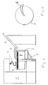
- Fig. 1 schematisch einen Querschnitt durch eine erfindungsgemäße Vorrichtung mit zugeordnetem Transportband und angehobener Platte,
- Fig. 2 eine Draufsicht auf den Teigkessel samt der zugehörigen Führungsschiene und
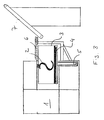
- Fig. 3 die Vorrichtung mit abgesonderter Platte.
- Bei dem in Fig. 1 dargestellten Schnitt durch ein Ausführungsbeispiel ist mit 1 das Gestell einer Vorrichtung zur Herstellung von Teig, beispielsweise eine Knetmaschine, bezeichnet, die mit einem rotierenden Knethaken 2 versehen ist. Dieser Knethaken 2 kann in einen Teigkessel 3 abgesenkt werden, der in herkömmlicher Weise entweder automatisch oder manuell mit den Teigzutaten gefüllt wird. Der Teigkessel 3 dreht sich, während der Knethaken 2 um seine Längsachse rotiert, so daß nach Ablauf einer gewissen Zeit die Zutaten zu einem fertigen Teig verknetet worden sind.
- Erfindungsgemäß ist nun im Teigkessel 3 eine dessen gesamten Querschnitt bedeckende, höhenverstellbare Platte 4 vorgesehen, die in Fig. 1 in ihrer oberen Stellung und in Fig. 3 in ihrer unteren Stellung dargestellt ist und die entlang des Doppelpfeiles durch eine Hubstange 5 bewegbar ist, die zentral und vertikal den Teigkessel 3 durchsetzt. Während des Knetvorganges befindet sich die Platte 4 in ihrer unteren, d.h. abgesenkten Stellung und dreht sich mit dem Teigkessel 3. Nach Beendigung des Knetvorgangs wird die Platte 4 durch die Hubstange 5 (elektrisch, mechanisch oder pneumatisch) angehoben, wobei sie ihre Drehung mit der gleichen Geschwindigkeit wie der Teigkessel 3 beibehält. Oberhalb des Teigkessels 3 ist eine Führungsschiene 6 vorgesehen, die sich in der Nähe des Randes des Teigkessels 3 bis zu dessen gedachter Achse erstreckt (Fig. 2), wobei die Führungsschiene an ihrer Unterseite zur Abtrennung eines Teigstreifens mit einer Messerkante versehen ist; die Führungsschiene 6 weist ferner die Form einer Hohlkehle auf, wobei die konkave Seite dem ihr zufließenden Teig zugewandt ist; ferner ist die Führungsschiene 6 in Längsrichtung gekrümmt.
- Die sich kontinuierlich nach oben bewegende Platte 4 mit dem auf ihr liegenden fertigen Teig nähert sich der Führungsschiene 6, wobei diese, aufgrund ihrer messerartigen Unterseite sowie der gekrümmten und hohlen Form, einen Teigstreifen abschneidet, der dem Förderband 7 zugeführt wird. Dieser kontinuierliche vom Teigvorrat abgeschnittene Teigstrang wird ohne Unterbrechung dem Förderband 7 zugeführt, bis der Teigvorrat im Teigkessel 3, d.h. auf der im Teigkessel 3 sich befindlichen Platte 4 vollständig, d.h. restlos, abgeführt worden ist.
- Danach wird die Platte 4 abgesenkt, wonach der Teigkessel erneut mit den entsprechenden Zutaten zur Herstellung eines Teiges gefüllt werden kann.
- Ein Zusammenpressen des Teiges beim Abführen erfolgt nicht, da dieser locker an der Führungsschiene 6 anliegt, so daß auch keine Kompression auftritt. Anstelle eines Knethakens S können auch andere in der Groß- und Kleinbäckerei bekannte Knetanordnungen verwendet werden, wie z.B. L-förmige Rührvorrichtungen für Roggenteige oder 88-Rühranordnungen anstelle des S-förmigen Knethakens.
Claims (4)
- Vorrichtung zur Herstellung von Teig, bestehend aus einer Knetanordnung (1,2), einem drehbar gelagerten Teigkessel (3) und einer Abfuhranordnung für den fertig gekneteten Teig, dadurch gekennzeichnet, daß die Abfuhranordnung eine den gesamten Teigkesselboden bedeckende, sich mit dem Teigkessel drehende Platte (4) aufweist, die auf einer mittig und zentral im Kessel (3) angeordneten Hubstange (5) gelagert ist, welche die Platte (4) mit dem fertig gekneteten Teig bis zu einer Stellung in der Nähe des oberen Randes des Teigkessels (3) kontinuierlich anhebt und eine sich vom Rand des Teigkessels bis zu dessen Achse radial sich erstreckende Führungsschiene (6) aufweist.
- Vorrichtung nach Anspruch 1, dadurch gekennzeichnet, daß die Führungsschiene (6) an ihrer Unterseite mit einer Messerkante versehen ist.
- Vorrichtung nach Ansprüchen 1 und 2, dadurch gekennzeichnet, daß die Führungsschiene (6) die Form einer Hohlkehle aufweist, wobei die konkave Seite dem Teig zugewandt ist.
- Vorrichtung nach Ansprüchen 1, 2 und 3, dadurch gekennzeichnet, daß die Führungsschiene (6) in Längsrichtung gekrümmt ist.
Applications Claiming Priority (2)
| Application Number | Priority Date | Filing Date | Title |
|---|---|---|---|
| DE4328922A DE4328922C1 (de) | 1993-08-27 | 1993-08-27 | Vorrichtung zur Herstellung von Teig |
| DE4328922 | 1993-08-27 |
Publications (2)
| Publication Number | Publication Date |
|---|---|
| EP0640287A1 EP0640287A1 (de) | 1995-03-01 |
| EP0640287B1 true EP0640287B1 (de) | 1996-10-30 |
Family
ID=6496212
Family Applications (1)
| Application Number | Title | Priority Date | Filing Date |
|---|---|---|---|
| EP94113399A Expired - Lifetime EP0640287B1 (de) | 1993-08-27 | 1994-08-26 | Vorrichtung zur Herstellung von Teig |
Country Status (4)
| Country | Link |
|---|---|
| EP (1) | EP0640287B1 (de) |
| AT (1) | ATE144683T1 (de) |
| DE (2) | DE4328922C1 (de) |
| ES (1) | ES2096387T3 (de) |
Families Citing this family (1)
| Publication number | Priority date | Publication date | Assignee | Title |
|---|---|---|---|---|
| CN112369441B (zh) * | 2020-10-22 | 2022-06-10 | 赣州市倞华菲尔雪食品有限公司 | 一种蛋糕制作用搅拌器及操作方法 |
Family Cites Families (3)
| Publication number | Priority date | Publication date | Assignee | Title |
|---|---|---|---|---|
| FR1529924A (fr) * | 1967-05-12 | 1968-06-21 | Machine diviseuse volumétrique pour pâtes et plus particulièrement pour pâtes deboulangerie et produits panifiables | |
| DE2421720C3 (de) * | 1974-05-04 | 1982-09-09 | Birgter Maschinenfabrik GmbH, 4441 Riesenbeck | Teigknetmaschine mit rotierendem Bottich |
| FR2659528B1 (fr) * | 1990-03-14 | 1992-07-24 | Dito Sama | Dispositif d'extraction de pate notamment d'un petrin a cuve cylindrique. |
-
1993
- 1993-08-27 DE DE4328922A patent/DE4328922C1/de not_active Expired - Fee Related
-
1994
- 1994-08-26 EP EP94113399A patent/EP0640287B1/de not_active Expired - Lifetime
- 1994-08-26 AT AT94113399T patent/ATE144683T1/de not_active IP Right Cessation
- 1994-08-26 ES ES94113399T patent/ES2096387T3/es not_active Expired - Lifetime
- 1994-08-26 DE DE59400938T patent/DE59400938D1/de not_active Expired - Fee Related
Also Published As
| Publication number | Publication date |
|---|---|
| EP0640287A1 (de) | 1995-03-01 |
| ES2096387T3 (es) | 1997-03-01 |
| ATE144683T1 (de) | 1996-11-15 |
| DE4328922C1 (de) | 1994-10-20 |
| DE59400938D1 (de) | 1996-12-05 |
Similar Documents
| Publication | Publication Date | Title |
|---|---|---|
| DE69003940T2 (de) | Herstellung eines Teigproduktes. | |
| DE3020167C2 (de) | ||
| EP0367968B1 (de) | Maschine zur Verarbeitung von Lebensmitteln oder zur Herstellung von Pharmazie- und Chemieprodukten | |
| DE69105402T2 (de) | Vorrichtung zum Bedecken einer horizontalen Oberfläche, wie eines Backbleches mit einem fliessfähigen Teig, insbesondere eines ungekochten essbaren Teiges. | |
| EP0640287B1 (de) | Vorrichtung zur Herstellung von Teig | |
| DE2421720A1 (de) | Teigknetmaschine mit rotierendem bottich | |
| DD213826A5 (de) | Vorrichtung zur bildung einer kugel aus plastischem material | |
| EP0133587A2 (de) | Käsefertiger | |
| DE4124600A1 (de) | Vorrichtung zum herstellen von kautschukmischungen | |
| DE69807044T2 (de) | Knetschüssel für die industrielle herstellung von teig zum backen von brot, wiener gebäck oder dergleichen | |
| EP0101674A2 (de) | Vorrichtung zur Herstellung von Teigstücken | |
| WO2020094802A1 (de) | Austragsvorrichtung für kompakte nahrungsmittelmassen, insbesondere riegelmassen oder keksteige | |
| DE2422963B1 (de) | Pneumatische Misch- und Abförderanlage für (ließfähige Schüttgüter | |
| DE1950110C3 (de) | Einrichtung zur fortlaufenden Erzeugung von Weichkäse in Stücken | |
| DE3322032C2 (de) | ||
| DE2112028A1 (de) | Verfahren zum Entmolken und Verdichten der Bruchmasse aus einem Molkenbruchgemisch,sowie Vorrichtung zur Anwendung dieses Verfahrens | |
| DE245354C (de) | ||
| DE944759C (de) | Vorrichtung zum kontinuierlichen Abfuellen von Hollaender-Kaesebruch | |
| DE10338146B4 (de) | Anlage zur Herstellung von Teig und Gebäck | |
| DE2701444C3 (de) | Vollautomatische Brotteigabwägemaschine | |
| EP0863084B1 (de) | Kit und Nachfüllbeutel zum Eindosieren eines Pulvers | |
| EP0276456B1 (de) | Verfahren und Vorrichtung zum Herstellen von Knäckebrot | |
| EP3259993B1 (de) | Vorrichtung zum portionieren von teigmasse | |
| DE8715463U1 (de) | Teigbehälter-Füllautomat | |
| DE87455C (de) |
Legal Events
| Date | Code | Title | Description |
|---|---|---|---|
| PUAI | Public reference made under article 153(3) epc to a published international application that has entered the european phase |
Free format text: ORIGINAL CODE: 0009012 |
|
| 17P | Request for examination filed |
Effective date: 19941227 |
|
| AK | Designated contracting states |
Kind code of ref document: A1 Designated state(s): AT BE CH DE DK ES FR GB GR IE IT LI LU MC NL PT SE |
|
| GRAG | Despatch of communication of intention to grant |
Free format text: ORIGINAL CODE: EPIDOS AGRA |
|
| 17Q | First examination report despatched |
Effective date: 19960205 |
|
| GRAH | Despatch of communication of intention to grant a patent |
Free format text: ORIGINAL CODE: EPIDOS IGRA |
|
| GRAH | Despatch of communication of intention to grant a patent |
Free format text: ORIGINAL CODE: EPIDOS IGRA |
|
| GRAA | (expected) grant |
Free format text: ORIGINAL CODE: 0009210 |
|
| AK | Designated contracting states |
Kind code of ref document: B1 Designated state(s): AT BE CH DE DK ES FR GB GR IE IT LI LU MC NL PT SE |
|
| PG25 | Lapsed in a contracting state [announced via postgrant information from national office to epo] |
Ref country code: NL Free format text: LAPSE BECAUSE OF FAILURE TO SUBMIT A TRANSLATION OF THE DESCRIPTION OR TO PAY THE FEE WITHIN THE PRESCRIBED TIME-LIMIT Effective date: 19961030 Ref country code: GR Free format text: LAPSE BECAUSE OF FAILURE TO SUBMIT A TRANSLATION OF THE DESCRIPTION OR TO PAY THE FEE WITHIN THE PRESCRIBED TIME-LIMIT Effective date: 19961030 Ref country code: DK Effective date: 19961030 |
|
| REF | Corresponds to: |
Ref document number: 144683 Country of ref document: AT Date of ref document: 19961115 Kind code of ref document: T |
|
| REF | Corresponds to: |
Ref document number: 59400938 Country of ref document: DE Date of ref document: 19961205 |
|
| REG | Reference to a national code |
Ref country code: IE Ref legal event code: FG4D Free format text: 70503 |
|
| ITF | It: translation for a ep patent filed | ||
| PG25 | Lapsed in a contracting state [announced via postgrant information from national office to epo] |
Ref country code: SE Effective date: 19970130 Ref country code: PT Effective date: 19970130 |
|
| ET | Fr: translation filed | ||
| GBT | Gb: translation of ep patent filed (gb section 77(6)(a)/1977) |
Effective date: 19970203 |
|
| REG | Reference to a national code |
Ref country code: ES Ref legal event code: FG2A Ref document number: 2096387 Country of ref document: ES Kind code of ref document: T3 |
|
| NLV1 | Nl: lapsed or annulled due to failure to fulfill the requirements of art. 29p and 29m of the patents act | ||
| PG25 | Lapsed in a contracting state [announced via postgrant information from national office to epo] |
Ref country code: IE Free format text: LAPSE BECAUSE OF NON-PAYMENT OF DUE FEES Effective date: 19970627 |
|
| REG | Reference to a national code |
Ref country code: IE Ref legal event code: FD4D Ref document number: 70503 Country of ref document: IE |
|
| PG25 | Lapsed in a contracting state [announced via postgrant information from national office to epo] |
Ref country code: LU Free format text: LAPSE BECAUSE OF NON-PAYMENT OF DUE FEES Effective date: 19970831 Ref country code: LI Free format text: LAPSE BECAUSE OF NON-PAYMENT OF DUE FEES Effective date: 19970831 Ref country code: CH Free format text: LAPSE BECAUSE OF NON-PAYMENT OF DUE FEES Effective date: 19970831 Ref country code: BE Effective date: 19970831 |
|
| PLBE | No opposition filed within time limit |
Free format text: ORIGINAL CODE: 0009261 |
|
| STAA | Information on the status of an ep patent application or granted ep patent |
Free format text: STATUS: NO OPPOSITION FILED WITHIN TIME LIMIT |
|
| PGFP | Annual fee paid to national office [announced via postgrant information from national office to epo] |
Ref country code: DE Payment date: 19971016 Year of fee payment: 4 |
|
| 26N | No opposition filed | ||
| BERE | Be: lapsed |
Owner name: PILLER OSWALD Effective date: 19970831 |
|
| PG25 | Lapsed in a contracting state [announced via postgrant information from national office to epo] |
Ref country code: MC Free format text: LAPSE BECAUSE OF NON-PAYMENT OF DUE FEES Effective date: 19980228 |
|
| REG | Reference to a national code |
Ref country code: CH Ref legal event code: PL |
|
| PG25 | Lapsed in a contracting state [announced via postgrant information from national office to epo] |
Ref country code: DE Free format text: LAPSE BECAUSE OF NON-PAYMENT OF DUE FEES Effective date: 19990601 |
|
| REG | Reference to a national code |
Ref country code: GB Ref legal event code: IF02 |
|
| PGFP | Annual fee paid to national office [announced via postgrant information from national office to epo] |
Ref country code: ES Payment date: 20020730 Year of fee payment: 9 |
|
| PGFP | Annual fee paid to national office [announced via postgrant information from national office to epo] |
Ref country code: AT Payment date: 20020814 Year of fee payment: 9 |
|
| PGFP | Annual fee paid to national office [announced via postgrant information from national office to epo] |
Ref country code: FR Payment date: 20020829 Year of fee payment: 9 |
|
| PGFP | Annual fee paid to national office [announced via postgrant information from national office to epo] |
Ref country code: GB Payment date: 20030813 Year of fee payment: 10 |
|
| PG25 | Lapsed in a contracting state [announced via postgrant information from national office to epo] |
Ref country code: AT Free format text: LAPSE BECAUSE OF NON-PAYMENT OF DUE FEES Effective date: 20030826 |
|
| PG25 | Lapsed in a contracting state [announced via postgrant information from national office to epo] |
Ref country code: ES Free format text: LAPSE BECAUSE OF NON-PAYMENT OF DUE FEES Effective date: 20030827 |
|
| PG25 | Lapsed in a contracting state [announced via postgrant information from national office to epo] |
Ref country code: FR Free format text: LAPSE BECAUSE OF NON-PAYMENT OF DUE FEES Effective date: 20040430 |
|
| REG | Reference to a national code |
Ref country code: FR Ref legal event code: ST |
|
| PG25 | Lapsed in a contracting state [announced via postgrant information from national office to epo] |
Ref country code: GB Free format text: LAPSE BECAUSE OF NON-PAYMENT OF DUE FEES Effective date: 20040826 |
|
| REG | Reference to a national code |
Ref country code: ES Ref legal event code: FD2A Effective date: 20030827 |
|
| GBPC | Gb: european patent ceased through non-payment of renewal fee |
Effective date: 20040826 |
|
| PG25 | Lapsed in a contracting state [announced via postgrant information from national office to epo] |
Ref country code: IT Free format text: LAPSE BECAUSE OF NON-PAYMENT OF DUE FEES;WARNING: LAPSES OF ITALIAN PATENTS WITH EFFECTIVE DATE BEFORE 2007 MAY HAVE OCCURRED AT ANY TIME BEFORE 2007. THE CORRECT EFFECTIVE DATE MAY BE DIFFERENT FROM THE ONE RECORDED. Effective date: 20050826 |