EP0639675B1 - Clapet anti-retour - Google Patents
Clapet anti-retour Download PDFInfo
- Publication number
- EP0639675B1 EP0639675B1 EP19940111682 EP94111682A EP0639675B1 EP 0639675 B1 EP0639675 B1 EP 0639675B1 EP 19940111682 EP19940111682 EP 19940111682 EP 94111682 A EP94111682 A EP 94111682A EP 0639675 B1 EP0639675 B1 EP 0639675B1
- Authority
- EP
- European Patent Office
- Prior art keywords
- sleeve
- section
- inner sleeve
- backflow
- outer sleeve
- Prior art date
- Legal status (The legal status is an assumption and is not a legal conclusion. Google has not performed a legal analysis and makes no representation as to the accuracy of the status listed.)
- Expired - Lifetime
Links
- 230000002265 prevention Effects 0.000 title 1
- XLYOFNOQVPJJNP-UHFFFAOYSA-N water Substances O XLYOFNOQVPJJNP-UHFFFAOYSA-N 0.000 claims abstract description 34
- 238000007789 sealing Methods 0.000 claims abstract description 30
- 239000013536 elastomeric material Substances 0.000 claims abstract 4
- 239000011324 bead Substances 0.000 claims description 5
- 230000001747 exhibiting effect Effects 0.000 claims 1
- 230000000694 effects Effects 0.000 abstract 1
- 239000013013 elastic material Substances 0.000 description 3
- 230000002093 peripheral effect Effects 0.000 description 3
- 230000007704 transition Effects 0.000 description 3
- 238000009423 ventilation Methods 0.000 description 3
- 230000007423 decrease Effects 0.000 description 2
- 239000012080 ambient air Substances 0.000 description 1
- 238000004873 anchoring Methods 0.000 description 1
- 230000000903 blocking effect Effects 0.000 description 1
- 238000010276 construction Methods 0.000 description 1
- 239000000356 contaminant Substances 0.000 description 1
- 238000002347 injection Methods 0.000 description 1
- 239000007924 injection Substances 0.000 description 1
- 238000003780 insertion Methods 0.000 description 1
- 230000037431 insertion Effects 0.000 description 1
- 238000009434 installation Methods 0.000 description 1
- 230000014759 maintenance of location Effects 0.000 description 1
- 238000004519 manufacturing process Methods 0.000 description 1
- 239000004576 sand Substances 0.000 description 1
- 230000008719 thickening Effects 0.000 description 1
- 238000013022 venting Methods 0.000 description 1
- 230000037303 wrinkles Effects 0.000 description 1
Images


Classifications
-
- E—FIXED CONSTRUCTIONS
- E03—WATER SUPPLY; SEWERAGE
- E03C—DOMESTIC PLUMBING INSTALLATIONS FOR FRESH WATER OR WASTE WATER; SINKS
- E03C1/00—Domestic plumbing installations for fresh water or waste water; Sinks
- E03C1/02—Plumbing installations for fresh water
- E03C1/10—Devices for preventing contamination of drinking-water pipes, e.g. means for aerating self-closing flushing valves
- E03C1/104—Devices for preventing contamination of drinking-water pipes, e.g. means for aerating self-closing flushing valves using a single check valve
-
- F—MECHANICAL ENGINEERING; LIGHTING; HEATING; WEAPONS; BLASTING
- F16—ENGINEERING ELEMENTS AND UNITS; GENERAL MEASURES FOR PRODUCING AND MAINTAINING EFFECTIVE FUNCTIONING OF MACHINES OR INSTALLATIONS; THERMAL INSULATION IN GENERAL
- F16K—VALVES; TAPS; COCKS; ACTUATING-FLOATS; DEVICES FOR VENTING OR AERATING
- F16K15/00—Check valves
- F16K15/14—Check valves with flexible valve members
- F16K15/144—Check valves with flexible valve members the closure elements being fixed along all or a part of their periphery
- F16K15/145—Check valves with flexible valve members the closure elements being fixed along all or a part of their periphery the closure elements being shaped as a solids of revolution, e.g. cylindrical or conical
-
- F—MECHANICAL ENGINEERING; LIGHTING; HEATING; WEAPONS; BLASTING
- F16—ENGINEERING ELEMENTS AND UNITS; GENERAL MEASURES FOR PRODUCING AND MAINTAINING EFFECTIVE FUNCTIONING OF MACHINES OR INSTALLATIONS; THERMAL INSULATION IN GENERAL
- F16K—VALVES; TAPS; COCKS; ACTUATING-FLOATS; DEVICES FOR VENTING OR AERATING
- F16K15/00—Check valves
- F16K15/14—Check valves with flexible valve members
- F16K15/148—Check valves with flexible valve members the closure elements being fixed in their centre
-
- Y—GENERAL TAGGING OF NEW TECHNOLOGICAL DEVELOPMENTS; GENERAL TAGGING OF CROSS-SECTIONAL TECHNOLOGIES SPANNING OVER SEVERAL SECTIONS OF THE IPC; TECHNICAL SUBJECTS COVERED BY FORMER USPC CROSS-REFERENCE ART COLLECTIONS [XRACs] AND DIGESTS
- Y10—TECHNICAL SUBJECTS COVERED BY FORMER USPC
- Y10T—TECHNICAL SUBJECTS COVERED BY FORMER US CLASSIFICATION
- Y10T137/00—Fluid handling
- Y10T137/7722—Line condition change responsive valves
- Y10T137/7837—Direct response valves [i.e., check valve type]
- Y10T137/7879—Resilient material valve
- Y10T137/788—Having expansible port
- Y10T137/7882—Having exit lip
-
- Y—GENERAL TAGGING OF NEW TECHNOLOGICAL DEVELOPMENTS; GENERAL TAGGING OF CROSS-SECTIONAL TECHNOLOGIES SPANNING OVER SEVERAL SECTIONS OF THE IPC; TECHNICAL SUBJECTS COVERED BY FORMER USPC CROSS-REFERENCE ART COLLECTIONS [XRACs] AND DIGESTS
- Y10—TECHNICAL SUBJECTS COVERED BY FORMER USPC
- Y10T—TECHNICAL SUBJECTS COVERED BY FORMER US CLASSIFICATION
- Y10T137/00—Fluid handling
- Y10T137/7722—Line condition change responsive valves
- Y10T137/7837—Direct response valves [i.e., check valve type]
- Y10T137/7879—Resilient material valve
- Y10T137/7888—With valve member flexing about securement
- Y10T137/7889—Sleeve
Definitions
- the present patent application relates to a backflow preventer for sanitary facilities, in particular sanitary fittings.
- Backflow preventers or check valves are used in sanitary facilities to prevent water from flowing back into a feed line if there is negative pressure in it, for example as a result of a broken pipe.
- sanitary fittings with hose showers in particular, there is a risk that dirty water is sucked back into the feed line if the shower head is immersed in the dirty water when the control cartridge of the fitting is open.
- poppet valves are used as non-return valves in the sanitary sector.
- a valve disk is pressed against a valve seat by means of a spring, so that they close tightly even at very low backflow pressures.
- the guides wear over time, which can result in the disc valves no longer sealing.
- Another problem with poppet valves is that leakage can be significant if foreign objects enter; For example, when a grain of sand is trapped between the valve plate and the valve seat, a considerable flow cross section can remain free.
- Ball valves are also used as non-return valves. These low cost valves suffer practically no wear and are responsive with light balls. In the event of a fault caused by foreign bodies, however, the same problems arise as with poppet valves. Since the balls are not spring-loaded, they show unstable behavior at low backflow pressures.
- duckbill valves have a cup-shaped or hollow wedge-shaped valve body made of rubber-elastic material, which is held in a housing.
- the wedge-shaped valve body has a straight slot at the tapered end, which connects the inside of the valve body with the surroundings.
- the wall of the valve body delimiting the slot thus forms sealing lips.
- the cup-like valve bodies have a rectilinear slot in the region of the base, which is delimited by sealing lips protruding towards the outside and formed on the base. If there is excess pressure in the interior of the valve body, the slots open and the water can flow out through them. However, if there is negative pressure in the interior, the sealing lips are pressed against each other by the higher ambient pressure and backflow is prevented.
- valves have practically no wear at low manufacturing costs and still have a relatively good closing behavior when foreign bodies have penetrated into the slot, since the thin sealing lips nestle against them. It is disadvantageous, however, that the sealing lips only come into complete contact with one another when the back pressure is relatively high; they therefore show unstable behavior at very low back pressure.
- non-return devices which suck water back Prevent from toilet bowls into the feed line by simultaneously venting the rinsing line in the event of a negative pressure on the feed water line side and preventing water from being sucked back by a check valve-like part.
- An outer sleeve is inserted into the passage of a tubular housing, which is fastened to the housing with its end region on the inlet side and is supported radially via an inner flange. With regard to the inner flange downstream, the outer sleeve has a central cylindrical section, to which an expanding end section adjoins.
- the housing In the area of the middle section, the housing is provided with radial passages which are connected to the ambient air. Downstream of these passages, the housing has a further inner flange which, together with the outer sleeve, delimits an annular ventilation gap and whose end face facing away from the passages is conical.
- a bell-like inner sleeve is located inside the outer sleeve and lies with its free end region at a distance from the free end of the outer sleeve, at the end section thereof. When water flows through it, the outer sleeve expands and rests with its end section on the end face of the further inner flange in order to close the ventilation gap. This prevents water from escaping through the passages.
- the inner cuff bends inward to form folds. If there is negative pressure on the feed side, the outer sleeve is bent inwards so that its end section fits snugly against the inner sleeve to prevent water from flowing back. At the same time, the ventilation gap is free to ventilate the outlet. Since thin-walled bell-like collars form wave-like folds or kinks when bent inwards, is a Subsequent clean application on the outer sleeve is only guaranteed if the inner lateral surface of the end section is adapted in accordance with the outer contour of the inner sleeve interacting with it. In other words, the outer cuff may rest against the inner cuff with little or no prestressing. This can mean that a clean closing of the valve is no longer guaranteed at low backflow pressures.
- the outer sleeve interacts with a support section of the inner sleeve, which is shaped and dimensioned in such a way that it does not form wrinkles due to the flowing water and assumes a wave-like or kinked shape, the outer sleeve can lie against the inner sleeve under considerable pretension without any risk of that there are voids between the cuffs. This also reliably prevents water from flowing back.
- the sealing lip-like design of the free end areas of the outer and inner sleeves allows them to fit snugly against any foreign bodies. The leakage rate is thus reduced to a minimum even with foreign bodies trapped between the outer and inner sleeves. Since the outer cuff ends at the free end of the inner cuff, the danger is eliminated that with one on the outlet side, the water column running onto the cuffs, one of the sealing lips stands out from the other.
- the danger arises that water flowing in from the outlet side lifts the stretchable outer sleeve from the inner sleeve.
- the support section can elastically dodge the flowing water in order to release the flow cross section. At the same time, if there is excess pressure on the outlet side, the support and sealing lip section is pressed against the outer sleeve.
- Claims 9 and 10 relate to a preferred embodiment for securely fixing the inner sleeve to the support body. This embodiment results in a firm and immovable fit of the inner sleeve, especially in the blocking direction.
- the check valve (check valve) shown in FIG. 1 is particularly simple in construction and has only three parts: a housing 10 preferably made of plastic, an outer sleeve 12 and an inner sleeve 14, both made of rubber-elastic material.
- the inlet side of the backflow preventer is designated 16 and the outlet side 18.
- the arrow S indicates the direction of flow of the water.
- the housing 10 which has the housing part 22, the ribs 26 and the support body 28, is a one-piece injection molded part.
- the shaft-like shaped support body 28 stands out from those arranged on the outlet side 18 of the non-return valve Ribs 26 in the direction against the inlet side 16 and has a step-like taper 30, so that the free end forms a stub 32 on which the inner sleeve 14 sits with its hat-like fastening section 34.
- the diameter of the stub 32 is larger than the corresponding recess in the inner sleeve 14, so that due to its elasticity it lies against the stub 32 with a high level of friction.
- a form-fitting attachment for example by means of grooves and beads, is also conceivable.
- the fastening section 34 is adjoined by a conically widening central section 36, seen in the flow direction S, to which a cylindrical support section 38 connects, to which in turn a sealing lip section 42 extends up to the free end 40.
- the wall thickness of the inner sleeve 14 is approximately the same in the area of the central section 36 and the support section 38 and is selected such that the support section 38 cannot buckle or fold in in the direction of the axis 20 due to the water pressure customary in sanitary systems.
- the kink-like transition from the conical middle section 36 into the support section 38 leads to a stiffening of the inner sleeve 14 and supports the folding strength.
- the wall thickness of the inner sleeve 14 tapers, as seen in the flow direction S, so that a soft sealing lip is formed.
- the cylindrical outer jacket surface common to the support section 38 and sealing lip section 42 is designated by 44.
- the outer sleeve 12 has a brim-like design on the inlet side 16 and, with its brim 46, encompasses the end of the housing part 22 on this side and engages with its outer brim edge section 48 in a peripheral recess 50 of the housing part 22, which extends to the end of the housing part 22 on this side.
- a peripheral recess 50 of the housing part 22 which extends to the end of the housing part 22 on this side. 1 to the left of the axis 20 and to the right of the axis 20, two different designs of the peripheral recess 50 and the correspondingly shaped brim edge section 48 are shown.
- the bottom of the circumferential recess 50 is essentially cylindrical and the brim edge section 48 has a circumferential bead 52 protruding radially beyond the housing part 22 in the end region.
- the circumferential recess 50 is provided with an undercut 54, into which a thickened portion 52 ′ which is formed at the free end of the brim edge portion 48 engages and which also protrudes beyond the housing part 22 when viewed in the radial direction.
- the outer sleeve 12 lies with a root area 56 adjoining the brim 46 on the inner wall of the housing part 22 and then, viewed in the direction of flow S, merges into a sleeve section 58 which is spaced apart from the case part 22 and whose wall thickness decreases in a transition area 60, then approximately constant up to a sealing lip-like tapering end section 62.
- the outer sleeve 12 bears against the lateral surface 44 under prestress.
- the transition area 60 ends, seen in the flow direction S, at the lateral surface 44 and the sealing lip-like end section 62 interacts with the sealing lip section 42 of the inner sleeve 14 as a lip seal. Seen downstream, the outer cuff 12 ends at the free end 40 of the inner cuff 14.
- the backflow preventer shown in FIG. 1 is intended to be inserted into a cylindrical housing recess 64 of a sanitary fitting, in particular with a hose shower.
- the brim 46 acts as a seal and the peripheral bead 52 or the thickening 52 'serve for centering.
- the backflow preventer shown in FIG. 1 functions as follows: If no water flows in the flow direction S, the outer sleeve 12 lies against the inner sleeve 14 with a prestress. The pressure of the water flowing in the direction of flow S leads to the expansion of the outer sleeve 12 in the area of the sleeve section 58, which can deflect in the radial direction. As a result, the outer sleeve 12 is lifted from the inner sleeve 14, which essentially maintains its original shape, so that the water can flow through and can flow out through the openings between the ribs 26. If the water flow is interrupted, the outer cuff 12 securely rests against the lateral surface 44 of the inner cuff 14 due to its pretension. At backflow pressure, ie when the inlet-side pressure is less than the outlet-side pressure, the outer and inner sleeves 12, 14 are pressed against one another even more.
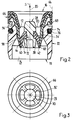
- the embodiment of the backflow preventer shown in FIGS. 2 and 3 also has a housing part 22 which is rotationally symmetrical with respect to the axis 20. Seen from the inlet side 16 in the direction of the outlet side 18, the passage 24 delimited by the housing part 22 becomes narrower, then has a substantially constant cross section in the central region and is then expanded again.
- the outer sleeve 12 lies with its root area 56, which also covers the end face of the housing part 22 on the inlet side. In the root region 56, the outer sleeve 12 is held clamped between the housing part 22 and a fastening sleeve 66, which is fastened to the housing part 22 via a snap connection 68 on the outside of the latter.
- a conical sleeve section 58 adjoins the root region 56, which is released from the housing part 22 when the water is not flowing in the flow direction S.
- ribs 26 ′ protruding on the fastening sleeve 66 in the direction against the axis 20 are formed on which, on the other hand, a substantially cylindrical support body 28 is formed, which is rotationally symmetrical to the axis 20.
- Flow passages 70 are delimited by the ribs 26 ', the support body 28 and the fastening sleeve 66.
- a circumferential groove 72 is formed on the support body 28, into which the bell-like inner sleeve 14 engages with its fastening part 34 '.
- the inner sleeve 14 From the free end 42 facing the outlet side 18 in the direction toward the inlet side 16, the inner sleeve 14 has an outer lateral surface 44 on which the Outer sleeve 12 bears flat under pretension and which, viewed in the flow direction S, is designed to taper conically in accordance with the section of the outer sleeve interacting with it.
- the foldable support section 38 adjoining the fastening section 34 ′ extends in the axial direction at least over part of the lateral surface 44 is deformable.
- the wall thickness of the outer sleeve 12 also decreases continuously in the section with which it rests on the inner sleeve 14, viewed in the flow direction S, the highly elastic end section 62 forming a lip seal together with the sealing lip section 42 of the inner sleeve 14.
- the housing has a groove 74 which is open towards the outside in the radial direction and in which a sealing ring 76 is arranged, which serves to center the backflow preventer inserted into a housing recess 64 indicated by a dot-dash line and the flow of water between the backflow preventer and the fitting housing to prevent.
- the backflow preventer shown in FIGS. 2 and 3 functions in the same manner as the embodiment described above and shown in FIG. 1. If no water flows, the outer sleeve 12 lies against the inner sleeve 14 with a prestress. If water now flows in the flow direction S under the pressures customary in sanitary facilities, the outer sleeve 12 expands and lies against the cylindrical middle part of the Housing part 22. This opens up a flow opening between the outer and inner sleeves 12, 14. If the water flow is interrupted, the outer sleeve 12 immediately rests on the outer surface 44.
- the lip seal on the outlet-side end of the outer and inner sleeve 12, 14 leads to a good sealing behavior, even if foreign bodies are present in between, since the sealing lip section 42 and the end section 62 abut against them.
- a very low leakage rate is guaranteed even if an elongated foreign body should extend along the entire lateral surface 44.
- FIG. 4 differs from that in FIG. 1 in particular by the attachment of the inner sleeve 14 'to the rotationally symmetrical support body 28', but also by the attachment of the outer sleeve 12 'to the tubular housing part 22'.
- the support body 28 ' which is also connected to the tubular housing part 22' by ribs 26 'according to FIG. 4, has an opening 78 which extends in the axial direction 20 in its center.
- this opening 78 is made of a rubber elastic Material existing inner sleeve 14 'by means of a one-piece molded, extending in the direction of the outlet end 18 pin 80 button-like.
- the opening 78 has a bottleneck 82 and the pin 80 has a section 84 at its end, the outside diameter of which is larger than the inside diameter of the bottleneck 82.
- the pin 80 is inserted with its section 84 through the bottleneck 82, the section 84 of the pin is compressed to return to its original shape after passing the bottleneck 82.
- the opening 78 has a conical region 88 which widens in the direction of the outlet end 18 between a cylindrical region 86 and the bottleneck 82.
- the pin 80 is shown in full, while the remaining part of the inner sleeve 14 'is shown in longitudinal section.
- a cylindrical support section 38' directly adjoins an approximately hemispherical hat-like fastening section 34 ''.
- the outer sleeve 12 'in FIG. 4 is fastened to an edge section 90 of the tubular housing part 22' by means of a brim 46 '.
- the edge section 90 has on its outside a circumferential web 92 which engages in an annular groove 94 in the brim 46 '.
- the brim 46 In the area of the annular groove 94, the brim 46 'has an annular bead 96 on its outside, which serves as a seal when the backflow preventer is inserted into a cylindrical housing recess, as is indicated, for example, in FIG. 2 at 64.
- FIG. 4 is essentially characterized by the secure anchoring of the outer and inner sleeves 12 ', 14' on the housing part 22 'or on the support body 28'.
Landscapes
- Engineering & Computer Science (AREA)
- General Engineering & Computer Science (AREA)
- Mechanical Engineering (AREA)
- Public Health (AREA)
- Life Sciences & Earth Sciences (AREA)
- Hydrology & Water Resources (AREA)
- Health & Medical Sciences (AREA)
- Water Supply & Treatment (AREA)
- Check Valves (AREA)
- Bidet-Like Cleaning Device And Other Flush Toilet Accessories (AREA)
- Casings For Electric Apparatus (AREA)
- Toilet Supplies (AREA)
- Iron Core Of Rotating Electric Machines (AREA)
- Valve-Gear Or Valve Arrangements (AREA)
- Control Of The Air-Fuel Ratio Of Carburetors (AREA)
Claims (10)
- Clapet anti-retour pour installations sanitaires, notamment pour robinetteries sanitaires, avec un boîtier (22, 22') présentant un passage (24), une manchette extérieure (12, 12') en matière caoutchouc élastique disposée dans le passage (24) et fixée hermétiquement sur le boîtier (22, 22'), lequel présente une section de manchette (58) faisant face à l'extrémité de sortie (18) du passage (24) et se terminant librement, extensible de manière élastique lorsque de l'eau s'écoule de l'extrémité d'entrée (16) du passage (24) vers l'extrémité de sortie (18) au travers de la manchette extérieure (12, 12'), et une manchette intérieure (14, 14'), enveloppée par la manchette extérieure (12, 12') fixée à demeure sur le boîtier, et présentant une section de support (38, 38') qui ne se plisse pas sous la pression de l'eau et une section en lèvre d'étanchéité (42) en direction de l'extrémité de sortie (18), se raccordant à celle-ci, la section (58) de la manchette extérieure (12, 12') enveloppant la manchette intérieure (14, 14') sous la précontrainte de la section de support et de la section en lèvre (38, 38', 42) par le fait que la zone agissant conjointement avec la section en lèvre d'étanchéité (42) est réalisée sous la forme d'un rebord étanche et se termine au moins à peu près au niveau de l'extrémité libre (42) de la manchette intérieure (14, 14').
- Clapet anti-retour selon la revendication 1, caractérisé par le fait que la manchette intérieure (14, 14') est réalisée en une seule pièce et qu'elle se compose d'une matière en caoutchouc élastique.
- Clapet anti-retour selon la revendication 1 ou 2, caractérisé par le fait que la surface d'enveloppe (44) des sections de support et en lèvre d'étanchéité (38, 38', 42), agissant conjointement avec la manchette extérieure (12, 12'), est de forme cylindrique ou conique, effilée en direction de l'extrémité de sortie (18).
- Clapet anti-retour selon l'une des revendications 1 à 3, caractérisé par le fait que des nervures (26, 26') en saillie dans le passage (24), s'éloignent du boîtier (22, 22') en aval de la manchette extérieure (12), ces nervures présentant un corps de support (28, 28') sur lequel est disposée la manchette intérieure (14, 14').
- Clapet anti-retour selon la revendication 4, caractérisé par le fait que la manchette intérieure (14, 14') est réalisée sous la forme d'une coupe et entoure, en le recouvrant, le corps (28, 28'), sur le côté faisant face à l'entrée (16).
- Clapet anti-retour selon la revendication 5, caractérisé par le fait qu'existe un espace libre entre la section de support (38, 38') de la manchette intérieure (14, 14') et le corps (28, 28').
- Clapet anti-retour selon l'une des revendications 1 à 6, caractérisé par le fait que la manchette extérieure (12, 12') est réalisée sous la forme d'un rebord dans la zone d'extrémité du côté de l'entrée et qu'elle recouvre l'extrémité du boîtier (22, 22') qui se trouve de ce côté.
- Clapet anti-retour selon la revendication 7, caractérisé par le fait qu'un bourrelet (52, 52', 96), périphérique, est façonné sur le rebord (46, 46') de la manchette extérieure (12, 12'), sur le côté extérieur du boîtier (22, 22').
- Clapet anti-retour selon l'une des revendications 4 à 8, caractérisé par le fait que le corps de support (28') présente, en son centre, une ouverture (78), s'étendant dans le sens axial, dans laquelle la manchette intérieure (14'), composée d'une matière en caoutchouc élastique, est fixée à l'aide d'un tenon (80), façonné et s'étendant en direction de l'extrémité de sortie (18).
- Clapet anti-retour selon la revendication 9, caractérisé par le fait que l'ouverture (78) dans le corps de support (28') présente un goulot d'étranglement (82), que le tenon (80) de la manchette intérieure (14') présente à son extrémité extérieure une découpe (84) dont le diamètre externe est supérieur au diamètre interne du goulot d'étranglement (82) et que cette découpe (84) passe au travers du goulot d'étranglement (82) à la manière d'un bouton.
Applications Claiming Priority (2)
| Application Number | Priority Date | Filing Date | Title |
|---|---|---|---|
| CH244793 | 1993-08-17 | ||
| CH2447/93 | 1993-08-17 |
Publications (2)
| Publication Number | Publication Date |
|---|---|
| EP0639675A1 EP0639675A1 (fr) | 1995-02-22 |
| EP0639675B1 true EP0639675B1 (fr) | 1997-09-24 |
Family
ID=4234042
Family Applications (1)
| Application Number | Title | Priority Date | Filing Date |
|---|---|---|---|
| EP19940111682 Expired - Lifetime EP0639675B1 (fr) | 1993-08-17 | 1994-07-27 | Clapet anti-retour |
Country Status (6)
| Country | Link |
|---|---|
| US (1) | US5551483A (fr) |
| EP (1) | EP0639675B1 (fr) |
| AT (1) | ATE158629T1 (fr) |
| CA (1) | CA2117515C (fr) |
| DE (1) | DE59404147D1 (fr) |
| ES (1) | ES2107094T3 (fr) |
Families Citing this family (16)
| Publication number | Priority date | Publication date | Assignee | Title |
|---|---|---|---|---|
| US6237625B1 (en) | 2000-02-23 | 2001-05-29 | Ronald E. Randolph | Dual plate check valve |
| US6766816B2 (en) * | 2001-10-03 | 2004-07-27 | Hunter Group, Inc. | Collapsible dispensing system |
| DE20118810U1 (de) * | 2001-11-17 | 2003-04-03 | Dieter Wildfang GmbH, 79379 Müllheim | Rückflußverhinderer |
| US6795987B2 (en) | 2002-09-17 | 2004-09-28 | Kenneth R. Cornwall | Trap guard device |
| DE10316903A1 (de) * | 2003-04-12 | 2004-10-28 | Neoperl Gmbh | Rückflussverhinderer |
| DE202005002415U1 (de) * | 2005-02-14 | 2005-04-21 | Hans Sasserath & Co. Kg | Bauteilsatz zum modularen Erstellen einer Ablaufanordnung |
| WO2011140508A1 (fr) | 2010-05-07 | 2011-11-10 | Alps, Llc | Vanne pour machine distributrice et procédé associé |
| ITRM20110384A1 (it) * | 2011-07-20 | 2013-01-21 | Seko Spa | Valvola di disconnessione a membrana flessibile, in particolare per la prevenzione del riflusso. |
| US9433327B2 (en) * | 2013-02-20 | 2016-09-06 | Ecolab Usa Inc. | Global backflow prevention assembly |
| EP2840191B1 (fr) * | 2013-08-21 | 2017-06-14 | Geberit International AG | Dispositif de siphon |
| SE538631C2 (sv) * | 2015-04-14 | 2016-10-04 | Staccato Tech Ab | Valve Seat |
| DE102016012646B4 (de) * | 2016-10-24 | 2018-05-03 | Neoperl Gmbh | Einsetzteil mit einem wasserführenden Patronengehäuse |
| EP3587876B1 (fr) * | 2018-06-22 | 2022-03-02 | Microtecnica S.r.l. | Soupape d'arrêt de régulation de pression, son piston et méthodes correspondantes de fabrication |
| DE102019202416A1 (de) * | 2019-02-22 | 2020-10-29 | Syntegon Technology Gmbh | Füllvorrichtung zum Abfüllen einer definierten Menge eines Produkts |
| GB2612650A (en) | 2021-11-09 | 2023-05-10 | Altecnic Ltd | Tundish with integral dry tap |
| FR3143087A1 (fr) * | 2022-12-08 | 2024-06-14 | Akwel | Clapet anti-retour. |
Family Cites Families (27)
| Publication number | Priority date | Publication date | Assignee | Title |
|---|---|---|---|---|
| DE206227C (fr) * | ||||
| NL292211A (fr) * | ||||
| DE114209C (fr) * | ||||
| DE609275C (de) * | 1935-02-11 | Friedrich Knop | Zapfventil mit zur Sicherung gegen Ruecksaugen von Schmutzwasser vorgesehenem Belueftungsventil | |
| US2270737A (en) * | 1940-07-26 | 1942-01-20 | Jesse D Langdon | Siphon breaker and valve |
| US2382427A (en) * | 1941-09-09 | 1945-08-14 | Jesse D Langdon | Siphon breaker and valve |
| US2621889A (en) * | 1947-05-23 | 1952-12-16 | Grove Regulator Company | Expansible sleeve type valve |
| US2675823A (en) * | 1949-09-07 | 1954-04-20 | Jesse D Langdon | Backflow preventer |
| DE1011732B (de) * | 1955-07-13 | 1957-07-04 | Draegerwerk Ag | Aus elastischem Material bestehendes Ventil fuer Atemschutzgeraete |
| CH344598A (de) * | 1955-09-28 | 1960-02-15 | Hans Schiebel Wasseraufbereitu | Rückschalgventil mit einer sich an eine Zylinderfläche anlegenden Membran |
| US2938532A (en) * | 1956-04-16 | 1960-05-31 | Speakman Co | Vacuum breaker |
| US3060882A (en) * | 1960-02-16 | 1962-10-30 | William H Peters | Automatic boat drain |
| US3171423A (en) * | 1961-07-24 | 1965-03-02 | Watts Regulator Co | Combination anti-siphon valve and backflow preventer |
| US3636968A (en) * | 1970-10-05 | 1972-01-25 | Watts Regulator Co | Cross-connection control valve |
| US3862640A (en) * | 1973-02-16 | 1975-01-28 | Iv Valentine Hechler | Anti-backflow water control and solution proportioner |
| CH571673A5 (fr) * | 1973-04-23 | 1976-01-15 | Braukmann Armaturen | |
| US3818929A (en) * | 1973-04-23 | 1974-06-25 | H Braukmann | Reduced pressure backflow preventer valve |
| US4013088A (en) * | 1975-05-19 | 1977-03-22 | Braukmann Armaturen Ag | Valve structure |
| US4013089A (en) * | 1975-09-17 | 1977-03-22 | Braukmann Armaturen Ag | Back flow preventer valve |
| US4726390A (en) * | 1986-03-26 | 1988-02-23 | Waltec, Inc. | Hose bibb vacuum breaker |
| DE3865992D1 (de) * | 1987-03-02 | 1991-12-12 | Schubert & Salzer Gmbh & Co In | Rohrunterbrecher. |
| DE3713878A1 (de) * | 1987-04-25 | 1988-11-10 | Schubert & Salzer Maschinen | Einen rohrunterbrecher aufweisende anschlussleitung fuer eine entnahmestelle |
| DE3832998C2 (de) * | 1988-09-29 | 1998-04-09 | Grohe Armaturen Friedrich | Rücksaugverhinderer |
| DE3839650C1 (fr) * | 1988-11-24 | 1990-02-15 | Hansa Metallwerke Ag, 7000 Stuttgart, De | |
| CH681164A5 (fr) * | 1989-12-13 | 1993-01-29 | Karrer Weber & Cie Ag | |
| CH681238A5 (fr) * | 1990-03-23 | 1993-02-15 | Karrer Weber & Cie Ag | |
| DE9113239U1 (de) * | 1991-10-24 | 1992-01-16 | Metallwerke Gebr. Seppelfricke Gmbh & Co, 4650 Gelsenkirchen | Unterputz-Rohrunterbrecher |
-
1994
- 1994-07-27 AT AT94111682T patent/ATE158629T1/de not_active IP Right Cessation
- 1994-07-27 DE DE59404147T patent/DE59404147D1/de not_active Expired - Fee Related
- 1994-07-27 ES ES94111682T patent/ES2107094T3/es not_active Expired - Lifetime
- 1994-07-27 EP EP19940111682 patent/EP0639675B1/fr not_active Expired - Lifetime
- 1994-08-16 CA CA 2117515 patent/CA2117515C/fr not_active Expired - Fee Related
- 1994-08-17 US US08/291,473 patent/US5551483A/en not_active Expired - Fee Related
Also Published As
| Publication number | Publication date |
|---|---|
| DE59404147D1 (de) | 1997-10-30 |
| ATE158629T1 (de) | 1997-10-15 |
| CA2117515A1 (fr) | 1995-02-18 |
| CA2117515C (fr) | 1998-06-16 |
| EP0639675A1 (fr) | 1995-02-22 |
| ES2107094T3 (es) | 1997-11-16 |
| US5551483A (en) | 1996-09-03 |
Similar Documents
| Publication | Publication Date | Title |
|---|---|---|
| EP0639675B1 (fr) | Clapet anti-retour | |
| DE4436879B4 (de) | Dichtungseinheit | |
| EP1485309B1 (fr) | Soupape | |
| DE3319869A1 (de) | Fuell- und entleerungsventil fuer aufblasbare hohlkoerper | |
| DE60004946T2 (de) | Rückschlagventil für medizinische Infusionsschläuche und dergleichen | |
| DE60020868T2 (de) | Ventilanlage für Fahrzeugspülsystem | |
| DE69832522T2 (de) | Tank-schnellverbindung mit rückschlagventil | |
| DE19828328A1 (de) | Stopfenanordnung zum Verschließen von Löchern in der Karosserie von Fahrzeugen | |
| DE60027471T2 (de) | Vorrichtung zur erzeugung einer einwegströmung | |
| EP3517212A1 (fr) | Dispositif de génération de jets de douche à vanne de surpression | |
| DE19826959A1 (de) | Druckspülsystem | |
| DE202005007872U1 (de) | Filtereinrichtung, insbesondere zur Flüssigkeitsfilterung in Brennkraftmaschinen | |
| DE69904275T2 (de) | Rückschlagventil für kraftstofftank | |
| EP0643175B1 (fr) | Dispositif de protection sanitaire empêchant le reflux d'eau | |
| EP0444414B1 (fr) | Installation sanitaire avec dispositif de protection pour empêcher les retours à eau | |
| DE2630972A1 (de) | Schliessdeckel fuer kessel | |
| DE102004044850B3 (de) | Rückflußverhinderer | |
| DE2445231A1 (de) | Rueckflussverhinderer | |
| DE1266591B (de) | Druckablassanordnung bei elastischen Dichtungsbalgen | |
| EP0571663A1 (fr) | Tuyau d'admission pour un moteur à combustion interne | |
| DE69417364T2 (de) | Aus Kunststoff geformtes Verbindungsteil und Rohrverbindung mit einem derartigen Teil | |
| DE69808250T2 (de) | Schwimmerventil für einen toilettenspülkasten | |
| DE102007006285A1 (de) | Rückflussverhinderer | |
| DE3410186A1 (de) | Fluessigkeitsmengenregler mit rueckschlagventil | |
| DE69716152T2 (de) | Hydro-Massage-Öffnung mit verbessertem Kreislauf von Luftzufuhr und Abfluss von Restwasser |
Legal Events
| Date | Code | Title | Description |
|---|---|---|---|
| PUAI | Public reference made under article 153(3) epc to a published international application that has entered the european phase |
Free format text: ORIGINAL CODE: 0009012 |
|
| AK | Designated contracting states |
Kind code of ref document: A1 Designated state(s): AT CH DE ES FR IT LI |
|
| 17P | Request for examination filed |
Effective date: 19950125 |
|
| GRAG | Despatch of communication of intention to grant |
Free format text: ORIGINAL CODE: EPIDOS AGRA |
|
| 17Q | First examination report despatched |
Effective date: 19970128 |
|
| GRAH | Despatch of communication of intention to grant a patent |
Free format text: ORIGINAL CODE: EPIDOS IGRA |
|
| GRAH | Despatch of communication of intention to grant a patent |
Free format text: ORIGINAL CODE: EPIDOS IGRA |
|
| GRAA | (expected) grant |
Free format text: ORIGINAL CODE: 0009210 |
|
| AK | Designated contracting states |
Kind code of ref document: B1 Designated state(s): AT CH DE ES FR IT LI |
|
| REF | Corresponds to: |
Ref document number: 158629 Country of ref document: AT Date of ref document: 19971015 Kind code of ref document: T |
|
| REG | Reference to a national code |
Ref country code: CH Ref legal event code: NV Representative=s name: PATENTANWAELTE SCHAAD, BALASS, MENZL & PARTNER AG Ref country code: CH Ref legal event code: EP |
|
| REF | Corresponds to: |
Ref document number: 59404147 Country of ref document: DE Date of ref document: 19971030 |
|
| ITF | It: translation for a ep patent filed | ||
| REG | Reference to a national code |
Ref country code: ES Ref legal event code: FG2A Ref document number: 2107094 Country of ref document: ES Kind code of ref document: T3 |
|
| ET | Fr: translation filed | ||
| PLBE | No opposition filed within time limit |
Free format text: ORIGINAL CODE: 0009261 |
|
| STAA | Information on the status of an ep patent application or granted ep patent |
Free format text: STATUS: NO OPPOSITION FILED WITHIN TIME LIMIT |
|
| 26N | No opposition filed | ||
| PGFP | Annual fee paid to national office [announced via postgrant information from national office to epo] |
Ref country code: AT Payment date: 20040705 Year of fee payment: 11 |
|
| PGFP | Annual fee paid to national office [announced via postgrant information from national office to epo] |
Ref country code: DE Payment date: 20040706 Year of fee payment: 11 |
|
| PGFP | Annual fee paid to national office [announced via postgrant information from national office to epo] |
Ref country code: FR Payment date: 20040708 Year of fee payment: 11 |
|
| PGFP | Annual fee paid to national office [announced via postgrant information from national office to epo] |
Ref country code: ES Payment date: 20040716 Year of fee payment: 11 |
|
| PGFP | Annual fee paid to national office [announced via postgrant information from national office to epo] |
Ref country code: CH Payment date: 20040723 Year of fee payment: 11 |
|
| PG25 | Lapsed in a contracting state [announced via postgrant information from national office to epo] |
Ref country code: IT Free format text: LAPSE BECAUSE OF NON-PAYMENT OF DUE FEES Effective date: 20050727 Ref country code: AT Free format text: LAPSE BECAUSE OF NON-PAYMENT OF DUE FEES Effective date: 20050727 |
|
| PG25 | Lapsed in a contracting state [announced via postgrant information from national office to epo] |
Ref country code: ES Free format text: LAPSE BECAUSE OF NON-PAYMENT OF DUE FEES Effective date: 20050728 |
|
| PG25 | Lapsed in a contracting state [announced via postgrant information from national office to epo] |
Ref country code: LI Free format text: LAPSE BECAUSE OF NON-PAYMENT OF DUE FEES Effective date: 20050731 Ref country code: CH Free format text: LAPSE BECAUSE OF NON-PAYMENT OF DUE FEES Effective date: 20050731 |
|
| PG25 | Lapsed in a contracting state [announced via postgrant information from national office to epo] |
Ref country code: DE Free format text: LAPSE BECAUSE OF NON-PAYMENT OF DUE FEES Effective date: 20060201 |
|
| REG | Reference to a national code |
Ref country code: CH Ref legal event code: PL |
|
| PG25 | Lapsed in a contracting state [announced via postgrant information from national office to epo] |
Ref country code: FR Free format text: LAPSE BECAUSE OF NON-PAYMENT OF DUE FEES Effective date: 20060331 |
|
| REG | Reference to a national code |
Ref country code: FR Ref legal event code: ST Effective date: 20060331 |
|
| REG | Reference to a national code |
Ref country code: ES Ref legal event code: FD2A Effective date: 20050728 |