EP0571663A1 - Tuyau d'admission pour un moteur à combustion interne - Google Patents
Tuyau d'admission pour un moteur à combustion interne Download PDFInfo
- Publication number
- EP0571663A1 EP0571663A1 EP92121555A EP92121555A EP0571663A1 EP 0571663 A1 EP0571663 A1 EP 0571663A1 EP 92121555 A EP92121555 A EP 92121555A EP 92121555 A EP92121555 A EP 92121555A EP 0571663 A1 EP0571663 A1 EP 0571663A1
- Authority
- EP
- European Patent Office
- Prior art keywords
- intake pipe
- pin
- pipe according
- designed
- ring sleeve
- Prior art date
- Legal status (The legal status is an assumption and is not a legal conclusion. Google has not performed a legal analysis and makes no representation as to the accuracy of the status listed.)
- Granted
Links
- 238000002485 combustion reaction Methods 0.000 title claims abstract description 12
- 239000013013 elastic material Substances 0.000 claims description 7
- 238000004519 manufacturing process Methods 0.000 description 5
- 238000003466 welding Methods 0.000 description 4
- 239000004033 plastic Substances 0.000 description 3
- 230000002787 reinforcement Effects 0.000 description 3
- 239000011324 bead Substances 0.000 description 2
- 239000004952 Polyamide Substances 0.000 description 1
- 238000004026 adhesive bonding Methods 0.000 description 1
- 230000009172 bursting Effects 0.000 description 1
- 239000000463 material Substances 0.000 description 1
- 239000007769 metal material Substances 0.000 description 1
- 229920002647 polyamide Polymers 0.000 description 1
- 238000009423 ventilation Methods 0.000 description 1
Images


Classifications
-
- F—MECHANICAL ENGINEERING; LIGHTING; HEATING; WEAPONS; BLASTING
- F02—COMBUSTION ENGINES; HOT-GAS OR COMBUSTION-PRODUCT ENGINE PLANTS
- F02M—SUPPLYING COMBUSTION ENGINES IN GENERAL WITH COMBUSTIBLE MIXTURES OR CONSTITUENTS THEREOF
- F02M35/00—Combustion-air cleaners, air intakes, intake silencers, or induction systems specially adapted for, or arranged on, internal-combustion engines
- F02M35/10—Air intakes; Induction systems
- F02M35/10091—Air intakes; Induction systems characterised by details of intake ducts: shapes; connections; arrangements
- F02M35/10144—Connections of intake ducts to each other or to another device
-
- F—MECHANICAL ENGINEERING; LIGHTING; HEATING; WEAPONS; BLASTING
- F02—COMBUSTION ENGINES; HOT-GAS OR COMBUSTION-PRODUCT ENGINE PLANTS
- F02M—SUPPLYING COMBUSTION ENGINES IN GENERAL WITH COMBUSTIBLE MIXTURES OR CONSTITUENTS THEREOF
- F02M35/00—Combustion-air cleaners, air intakes, intake silencers, or induction systems specially adapted for, or arranged on, internal-combustion engines
- F02M35/10—Air intakes; Induction systems
- F02M35/10006—Air intakes; Induction systems characterised by the position of elements of the air intake system in direction of the air intake flow, i.e. between ambient air inlet and supply to the combustion chamber
- F02M35/10026—Plenum chambers
- F02M35/10032—Plenum chambers specially shaped or arranged connecting duct between carburettor or air inlet duct and the plenum chamber; specially positioned carburettors or throttle bodies with respect to the plenum chamber
-
- F—MECHANICAL ENGINEERING; LIGHTING; HEATING; WEAPONS; BLASTING
- F02—COMBUSTION ENGINES; HOT-GAS OR COMBUSTION-PRODUCT ENGINE PLANTS
- F02M—SUPPLYING COMBUSTION ENGINES IN GENERAL WITH COMBUSTIBLE MIXTURES OR CONSTITUENTS THEREOF
- F02M35/00—Combustion-air cleaners, air intakes, intake silencers, or induction systems specially adapted for, or arranged on, internal-combustion engines
- F02M35/10—Air intakes; Induction systems
- F02M35/10209—Fluid connections to the air intake system; their arrangement of pipes, valves or the like
- F02M35/10236—Overpressure or vacuum relief means; Burst protection
-
- F—MECHANICAL ENGINEERING; LIGHTING; HEATING; WEAPONS; BLASTING
- F02—COMBUSTION ENGINES; HOT-GAS OR COMBUSTION-PRODUCT ENGINE PLANTS
- F02M—SUPPLYING COMBUSTION ENGINES IN GENERAL WITH COMBUSTIBLE MIXTURES OR CONSTITUENTS THEREOF
- F02M35/00—Combustion-air cleaners, air intakes, intake silencers, or induction systems specially adapted for, or arranged on, internal-combustion engines
- F02M35/10—Air intakes; Induction systems
- F02M35/10242—Devices or means connected to or integrated into air intakes; Air intakes combined with other engine or vehicle parts
- F02M35/10301—Flexible, resilient, pivotally or movable parts; Membranes
-
- F—MECHANICAL ENGINEERING; LIGHTING; HEATING; WEAPONS; BLASTING
- F02—COMBUSTION ENGINES; HOT-GAS OR COMBUSTION-PRODUCT ENGINE PLANTS
- F02M—SUPPLYING COMBUSTION ENGINES IN GENERAL WITH COMBUSTIBLE MIXTURES OR CONSTITUENTS THEREOF
- F02M35/00—Combustion-air cleaners, air intakes, intake silencers, or induction systems specially adapted for, or arranged on, internal-combustion engines
- F02M35/10—Air intakes; Induction systems
- F02M35/10314—Materials for intake systems
- F02M35/10321—Plastics; Composites; Rubbers
-
- F—MECHANICAL ENGINEERING; LIGHTING; HEATING; WEAPONS; BLASTING
- F02—COMBUSTION ENGINES; HOT-GAS OR COMBUSTION-PRODUCT ENGINE PLANTS
- F02M—SUPPLYING COMBUSTION ENGINES IN GENERAL WITH COMBUSTIBLE MIXTURES OR CONSTITUENTS THEREOF
- F02M35/00—Combustion-air cleaners, air intakes, intake silencers, or induction systems specially adapted for, or arranged on, internal-combustion engines
- F02M35/10—Air intakes; Induction systems
- F02M35/10209—Fluid connections to the air intake system; their arrangement of pipes, valves or the like
- F02M35/10229—Fluid connections to the air intake system; their arrangement of pipes, valves or the like the intake system acting as a vacuum or overpressure source for auxiliary devices, e.g. brake systems; Vacuum chambers
-
- F—MECHANICAL ENGINEERING; LIGHTING; HEATING; WEAPONS; BLASTING
- F02—COMBUSTION ENGINES; HOT-GAS OR COMBUSTION-PRODUCT ENGINE PLANTS
- F02M—SUPPLYING COMBUSTION ENGINES IN GENERAL WITH COMBUSTIBLE MIXTURES OR CONSTITUENTS THEREOF
- F02M35/00—Combustion-air cleaners, air intakes, intake silencers, or induction systems specially adapted for, or arranged on, internal-combustion engines
- F02M35/10—Air intakes; Induction systems
- F02M35/10373—Sensors for intake systems
-
- F—MECHANICAL ENGINEERING; LIGHTING; HEATING; WEAPONS; BLASTING
- F05—INDEXING SCHEMES RELATING TO ENGINES OR PUMPS IN VARIOUS SUBCLASSES OF CLASSES F01-F04
- F05C—INDEXING SCHEME RELATING TO MATERIALS, MATERIAL PROPERTIES OR MATERIAL CHARACTERISTICS FOR MACHINES, ENGINES OR PUMPS OTHER THAN NON-POSITIVE-DISPLACEMENT MACHINES OR ENGINES
- F05C2225/00—Synthetic polymers, e.g. plastics; Rubber
- F05C2225/08—Thermoplastics
-
- Y—GENERAL TAGGING OF NEW TECHNOLOGICAL DEVELOPMENTS; GENERAL TAGGING OF CROSS-SECTIONAL TECHNOLOGIES SPANNING OVER SEVERAL SECTIONS OF THE IPC; TECHNICAL SUBJECTS COVERED BY FORMER USPC CROSS-REFERENCE ART COLLECTIONS [XRACs] AND DIGESTS
- Y10—TECHNICAL SUBJECTS COVERED BY FORMER USPC
- Y10T—TECHNICAL SUBJECTS COVERED BY FORMER US CLASSIFICATION
- Y10T137/00—Fluid handling
- Y10T137/6851—With casing, support, protector or static constructional installations
- Y10T137/6855—Vehicle
Definitions
- the invention relates to an intake pipe for an internal combustion engine.
- Intake pipes for internal combustion engines are generally known and mostly consist of a metallic material or plastic.
- the wall thickness of the previously known intake pipes is often dimensioned such that combustion pressures, which can return to the intake pipe if the internal combustion engine is incorrectly set, can be absorbed without damage. It should be noted, however, that the wall thicknesses of such intake pipes have a considerable thickness, which is unsatisfactory both in terms of production technology and in terms of economy and function. Thin-walled plastic intake pipes often cannot withstand the overpressure that occurs and burst.
- the invention has for its object to further develop an intake pipe of the known type such that it is cheaper to manufacture in terms of production technology and economy, has a lower weight and withstands combustion pressures that can strike back into the intake pipe.
- the intake pipe comprises a safety valve which can be brought into the open position by a pressure in the interior which exceeds the atmospheric pressure. It is advantageous here that the wall thicknesses of the intake pipe can be dimensioned comparatively thin-walled, since excess pressure that can occur within the intake pipe is reduced via the safety valve.
- Such an intake pipe has good performance characteristics over a long period of use, is simple and inexpensive to manufacture from a manufacturing point of view and has a low weight.
- the safety valve can consist of a tubular ring sleeve made of rubber-elastic material, which covers at least one wall opening of a pin that is connected to the intake pipe in a flow-guiding manner. If there is any excess pressure within the intake pipe and thus within the pin, the tubular ring sleeve made of rubber-elastic material is also pressurized and lifts off the surface of the pin, so that there is a pressure equalization with the atmosphere. The ring sleeve is only loaded in the radial direction.
- the ring sleeve can be attached to the pin, for example, by a clamp or by a frictional and / or positive connection of the ring sleeve to the pin.
- the ring sleeve can, for example, be provided on the inner circumferential side on the side facing the suction pipe with an at least partially circumferential projection which is snapped into a circumferential groove of the pin which is open in the direction of the ring sleeve.
- the safety valve can consist of a ring sleeve made of rubber-elastic material, which sealingly encloses a wall opening in the intake pipe in the area of its outer diameter and a pin in the area of its inner diameter.
- the ring sleeve can be provided with reinforcement or stiffening ribs in the area of the wall opening of the intake pipe in order not to be deformed through the wall openings in the direction of the intake pipe in the case of the negative pressure which is usually present in the intake pipe.
- the pin can be designed as a vacuum connection or as a sensor connection.
- the ring sleeve is designed as a bellows, that the bellows and the pin each have an adapted surface profile and that the surface profiles can be sealingly engaged with one another when subjected to negative pressure. Due to the design of the pin according to the shape of the bellows, the two parts lie against each other in a gas-tight manner when subjected to negative pressure, so that predeterminable pressure conditions for engine control prevail in the intake pipe.
- the bellows can be reinforced in the area of its axial ends by annular beads, in order to ensure a secure fixation at least in the area of the intake pipe even when subjected to excess pressure.
- the outer diameter of the bellows remains largely tight in the area of the wall opening, while the otherwise tight connection between the pin and the bellows opens and ensures pressure equalization with the atmosphere. This reliably prevents the intake pipe from bursting.
- the ring sleeve and the pin can be designed as a preassembled unit and can be fastened together on the suction pipe.
- the unit can be fastened, for example, by a snap-in device which can be snapped into an opening in the intake pipe.
- Different mounting options are also conceivable, such as gluing or rotary welding.
- suction pipe according to the invention is explained in more detail below with reference to the drawings attached as an appendix. These show the individual components to be taken into account in a sectional and partially schematic representation.
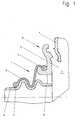
- FIG. 1 a section of an intake pipe is shown, in which the pin is designed as a vacuum connection and the ring sleeve, which is designed as a bellows, are designed as a preassembled unit and are subsequently connected to the intake pipe by rotary welding.
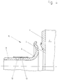
- FIG. 2 also shows a section of an intake pipe, the ring sleeve being fixed on the intake pipe on the one hand and in the axial direction on the other hand on a vacuum connection which can be snapped into the wall opening of the intake pipe.
- the suction pipe is made in one piece with a pin, which is designed as a vacuum connection, and has wall openings which are closed by the ring sleeve when subjected to vacuum.
- the ring cuff is not designed like a bellows.
- the safety valve is formed by a tubular ring sleeve, which covers a wall opening of the pin.
- FIGS. 1 to 4 each show an exemplary embodiment of an intake pipe for an internal combustion engine which is provided with a safety valve, the safety valve 1 being able to be brought into the open position by a pressure in the interior 2 which exceeds the atmospheric pressure.
- the safety valve 1 is formed by an annular sleeve made of rubber-elastic material, which is designed like a bellows and seals a wall opening 3, which can be used as a vacuum connection 8, when subjected to negative pressure.
- the vacuum connection 8 can for example be connected to the crankcase ventilation of the internal combustion engine.
- the bellows 9 is designed as a preassembled unit 10 with the vacuum port 8.
- the outer diameter 5 of the bellows 9 is held captive in an undercut and in the area of it
- the bellows 9 briefly lifts off the vacuum connection 8 until the overpressure is released from the intake pipe and a pressure equalization with the atmosphere is established.
- the bellows 9 can at least in the area of the Wall opening 3 of the intake pipe 4 may be provided with reinforcement or stiffening ribs.
- the preassembled unit 10 can be attached to the suction pipe by friction welding / rotary welding or snapping.
- the vacuum connection 8 is thereby spatially fixed in the axial direction.
- the ring sleeve in the form of a bellows 9 is connected on the one hand in the area of its outer diameter 5 to a receptacle formed in one piece with the intake pipe 4 and on the other hand in the area of its inner diameter 7 to the vacuum 8.
- the advantageous mode of operation does not differ from the mode of operation of the embodiment according to FIG. 1.
- the suction pipe 4 is integrally formed with a pin 6, wherein wall openings 3 are provided for the negative pressure.
- the ring sleeve is essentially S-shaped and has a circumferential bead in the area of its axial boundaries.
- the area of the ring sleeve, which can normally be subjected to negative pressure through the wall openings 3, can be provided with reinforcement, as a result of which consistently good performance characteristics are required over a long service life.
- FIG. 4 shows an exemplary embodiment similar to the exemplary embodiment from FIG. 1, wherein the ring sleeve is tubular and consists of a rubber-elastic material.
- the ring sleeve covers two wall openings 13 of the pin 6, which, like the pin 6, is made of the previous figures can be designed as a pipe or hose connection.
- the ring sleeve can be held, for example, by a clamp.
- the preassembled unit 10 can also be attached to the intake pipe, as described for FIG. 1.
- the intake pipes according to Figures 1 to 4 consist of a suitable plastic such. B. polyamide, as well as the two-piece vacuum port 8 formed in FIGS. 1 and 2, and a different choice of material is quite possible.
Landscapes
- Engineering & Computer Science (AREA)
- Chemical & Material Sciences (AREA)
- Combustion & Propulsion (AREA)
- Mechanical Engineering (AREA)
- General Engineering & Computer Science (AREA)
- Safety Valves (AREA)
- Supplying Secondary Fuel Or The Like To Fuel, Air Or Fuel-Air Mixtures (AREA)
- Check Valves (AREA)
- Exhaust-Gas Circulating Devices (AREA)
Applications Claiming Priority (2)
| Application Number | Priority Date | Filing Date | Title |
|---|---|---|---|
| DE4217191A DE4217191C2 (de) | 1992-05-23 | 1992-05-23 | Ansaugrohr für eine Verbrennungskraftmaschine |
| DE4217191 | 1992-05-23 |
Publications (2)
| Publication Number | Publication Date |
|---|---|
| EP0571663A1 true EP0571663A1 (fr) | 1993-12-01 |
| EP0571663B1 EP0571663B1 (fr) | 1996-03-06 |
Family
ID=6459633
Family Applications (1)
| Application Number | Title | Priority Date | Filing Date |
|---|---|---|---|
| EP92121555A Expired - Lifetime EP0571663B1 (fr) | 1992-05-23 | 1992-12-18 | Tuyau d'admission pour un moteur à combustion interne |
Country Status (4)
| Country | Link |
|---|---|
| US (1) | US5317995A (fr) |
| EP (1) | EP0571663B1 (fr) |
| JP (1) | JPH0674114A (fr) |
| DE (2) | DE4217191C2 (fr) |
Families Citing this family (9)
| Publication number | Priority date | Publication date | Assignee | Title |
|---|---|---|---|---|
| US5507256A (en) * | 1995-06-14 | 1996-04-16 | Ford Motor Company | Intake manifold positive pressure relief disk |
| DE29513019U1 (de) * | 1995-08-12 | 1995-10-19 | Fa. Andreas Stihl, 71336 Waiblingen | Verbrennungsmotor für ein handgeführtes Arbeitsgerät |
| US5771863A (en) * | 1996-10-11 | 1998-06-30 | Siemens Electric Limited | Integrated intake manifold and fuel rail with enclosed fuel filter |
| DE19826261A1 (de) * | 1998-06-15 | 1999-12-16 | Mann & Hummel Filter | Ansaugsystem |
| FR2793525B1 (fr) * | 1999-05-12 | 2001-07-27 | Mark Iv Systemes Moteurs Sa | Ensemble d'admission pour vehicule a moteur thermique comportant un moyen limiteur de surpression |
| WO2007006410A1 (fr) * | 2005-07-08 | 2007-01-18 | Mündener Gummiwerk Gmbh | Manchon d'un tuyau a air de suralimentation destine a fixer le tuyau a air de suralimentation sur une douille, et procede de fixation de ce manchon |
| DE102014002439B3 (de) * | 2014-02-20 | 2015-07-02 | Mtu Friedrichshafen Gmbh | Isolierung für eine Komponente eines Verbrennungsmotors |
| CN105370459B (zh) * | 2014-08-18 | 2018-05-25 | 陕西重型汽车有限公司 | 波纹管导向支撑件、组件及汽车进气系统 |
| US10711818B2 (en) | 2016-07-01 | 2020-07-14 | Mann+Hummel Gmbh | One-time only snap connection system mounting two parts and a sensor mounting system using the snap connection system |
Citations (5)
| Publication number | Priority date | Publication date | Assignee | Title |
|---|---|---|---|---|
| GB1267453A (en) * | 1968-04-22 | 1972-03-22 | Jarmuefejlesztesi Intezet | Fuel-supply system for an internal combustion engine |
| AU4863172A (en) * | 1971-11-09 | 1974-05-09 | James N. Kirby Pty. Ltd | Improvements in operation of air supply tubes to internal combustion engine carburettors |
| DE2342157A1 (de) * | 1973-08-21 | 1975-02-27 | Purolator Filter Gmbh | Anordnung eines ansaugrohres fuer luftfilter, insbesondere fuer brennkraftmaschinen |
| EP0280122A2 (fr) * | 1987-02-24 | 1988-08-31 | Bayerische Motoren Werke Aktiengesellschaft, Patentabteilung AJ-3 | Dispositif d'aspiration pour un moteur à combustion interne |
| GB2239898A (en) * | 1990-01-10 | 1991-07-17 | Rover Group | I.c. engine induction system |
Family Cites Families (7)
| Publication number | Priority date | Publication date | Assignee | Title |
|---|---|---|---|---|
| US3692337A (en) * | 1970-09-04 | 1972-09-19 | Avica Corp | Flexible coupling |
| US4133347A (en) * | 1977-10-31 | 1979-01-09 | Albert Mercer | Waste evacuation attachment for recreational vehicles |
| JPS57151034A (en) * | 1981-03-13 | 1982-09-18 | Nissan Motor Co Ltd | Control device of air-fuel ratio for internal combustion engine with supercharger |
| US4697829A (en) * | 1985-07-31 | 1987-10-06 | R J Pond Limited | Pipe connection joints |
| DE3536522A1 (de) * | 1985-10-12 | 1987-04-16 | Audi Ag | Saugrohr fuer eine brennkraftmaschine |
| US5150669A (en) * | 1989-11-06 | 1992-09-29 | General Motors Corporation | Pressure relief means for integrated induction system |
| US5009199A (en) * | 1990-06-08 | 1991-04-23 | General Motors Corporation | Intake reservoir for an engine having a check valve |
-
1992
- 1992-05-23 DE DE4217191A patent/DE4217191C2/de not_active Expired - Lifetime
- 1992-12-18 EP EP92121555A patent/EP0571663B1/fr not_active Expired - Lifetime
- 1992-12-18 DE DE59205608T patent/DE59205608D1/de not_active Expired - Lifetime
-
1993
- 1993-04-29 US US08/054,988 patent/US5317995A/en not_active Expired - Fee Related
- 1993-05-20 JP JP5118252A patent/JPH0674114A/ja active Pending
Patent Citations (5)
| Publication number | Priority date | Publication date | Assignee | Title |
|---|---|---|---|---|
| GB1267453A (en) * | 1968-04-22 | 1972-03-22 | Jarmuefejlesztesi Intezet | Fuel-supply system for an internal combustion engine |
| AU4863172A (en) * | 1971-11-09 | 1974-05-09 | James N. Kirby Pty. Ltd | Improvements in operation of air supply tubes to internal combustion engine carburettors |
| DE2342157A1 (de) * | 1973-08-21 | 1975-02-27 | Purolator Filter Gmbh | Anordnung eines ansaugrohres fuer luftfilter, insbesondere fuer brennkraftmaschinen |
| EP0280122A2 (fr) * | 1987-02-24 | 1988-08-31 | Bayerische Motoren Werke Aktiengesellschaft, Patentabteilung AJ-3 | Dispositif d'aspiration pour un moteur à combustion interne |
| GB2239898A (en) * | 1990-01-10 | 1991-07-17 | Rover Group | I.c. engine induction system |
Also Published As
| Publication number | Publication date |
|---|---|
| US5317995A (en) | 1994-06-07 |
| DE4217191A1 (de) | 1993-12-16 |
| DE59205608D1 (de) | 1996-04-11 |
| JPH0674114A (ja) | 1994-03-15 |
| DE4217191C2 (de) | 1994-03-31 |
| EP0571663B1 (fr) | 1996-03-06 |
Similar Documents
| Publication | Publication Date | Title |
|---|---|---|
| DE3829948C2 (fr) | ||
| DE69110900T2 (de) | Auf einer brennstoffleitung montierter druckregler. | |
| EP2054648B1 (fr) | Manchon d'étanchéité ou soufflet | |
| EP0728979B1 (fr) | Raccord étanche entre un tuyau en matière plastique et une pièce de raccordement fabriquée en métal | |
| DE2357803C2 (de) | Tankverschluß zum Verschließen eines eine Lippe aufweisenden Einfüllstutzens od. dgl. | |
| DE3744811C2 (fr) | ||
| DE19523645A1 (de) | Ventil zur Be- und Entlüftung für einen Behälter | |
| DE69832522T2 (de) | Tank-schnellverbindung mit rückschlagventil | |
| EP0571663B1 (fr) | Tuyau d'admission pour un moteur à combustion interne | |
| EP0351520B1 (fr) | Conduit d'admission d'air pour un moteur à combustion | |
| EP1147925A2 (fr) | Dispositif d'étanchéité | |
| DE4124683C2 (de) | Unterdruck-Bremskraftverstärker | |
| EP1024322B1 (fr) | Manchon de raccord | |
| WO2001003957A1 (fr) | Dispositif d'amortissement pneumatique a fermeture automatique | |
| DE3904106A1 (de) | Entlueftungsschlauch | |
| EP0929759A1 (fr) | Ressort pneumatique | |
| DE3024092A1 (de) | Hydraulisch daempfendes einkammerlager | |
| DE102016103549B3 (de) | Ventilvorrichtung für eine Verbrennungskraftmaschine | |
| EP1323958A1 (fr) | Joint d'étanchéité | |
| DE102018108976A1 (de) | Druckbegrenzungsventil | |
| DE19804552A1 (de) | Rückschlagventil | |
| DE10020640A1 (de) | Universalgelenk | |
| WO2017137203A1 (fr) | Système de sortie de gaz d'échappement pour un véhicule automobile, véhicule automobile doté d'un tel système de sortie de gaz d'échappement et procédé de production d'un système de sortie de gaz d'échappement | |
| EP0770792A1 (fr) | Unité cylindre-piston rempli avec un fluide, en particulier ressort à gaz | |
| DE19912249C2 (de) | Ventil für eine Milchleitung |
Legal Events
| Date | Code | Title | Description |
|---|---|---|---|
| PUAI | Public reference made under article 153(3) epc to a published international application that has entered the european phase |
Free format text: ORIGINAL CODE: 0009012 |
|
| 17P | Request for examination filed |
Effective date: 19930916 |
|
| AK | Designated contracting states |
Kind code of ref document: A1 Designated state(s): DE FR GB IT NL SE |
|
| RAP3 | Party data changed (applicant data changed or rights of an application transferred) |
Owner name: FIRMA CARL FREUDENBERG |
|
| RBV | Designated contracting states (corrected) |
Designated state(s): DE FR GB |
|
| 17Q | First examination report despatched |
Effective date: 19941229 |
|
| GRAA | (expected) grant |
Free format text: ORIGINAL CODE: 0009210 |
|
| AK | Designated contracting states |
Kind code of ref document: B1 Designated state(s): DE FR GB |
|
| REF | Corresponds to: |
Ref document number: 59205608 Country of ref document: DE Date of ref document: 19960411 |
|
| GBT | Gb: translation of ep patent filed (gb section 77(6)(a)/1977) |
Effective date: 19960327 |
|
| ET | Fr: translation filed | ||
| PG25 | Lapsed in a contracting state [announced via postgrant information from national office to epo] |
Ref country code: DE Effective date: 19961126 |
|
| PG25 | Lapsed in a contracting state [announced via postgrant information from national office to epo] |
Ref country code: GB Effective date: 19961218 |
|
| PLBE | No opposition filed within time limit |
Free format text: ORIGINAL CODE: 0009261 |
|
| STAA | Information on the status of an ep patent application or granted ep patent |
Free format text: STATUS: NO OPPOSITION FILED WITHIN TIME LIMIT |
|
| 26N | No opposition filed | ||
| GBPC | Gb: european patent ceased through non-payment of renewal fee |
Effective date: 19961218 |
|
| PG25 | Lapsed in a contracting state [announced via postgrant information from national office to epo] |
Ref country code: FR Effective date: 19970829 |
|
| REG | Reference to a national code |
Ref country code: FR Ref legal event code: ST |