EP0637745A1 - Automatisches prüfgerät für fischaugen in kunststoff und vorrichtung und methode zur herstellung einer kunststoffolie zur prüfung - Google Patents
Automatisches prüfgerät für fischaugen in kunststoff und vorrichtung und methode zur herstellung einer kunststoffolie zur prüfung Download PDFInfo
- Publication number
- EP0637745A1 EP0637745A1 EP94907691A EP94907691A EP0637745A1 EP 0637745 A1 EP0637745 A1 EP 0637745A1 EP 94907691 A EP94907691 A EP 94907691A EP 94907691 A EP94907691 A EP 94907691A EP 0637745 A1 EP0637745 A1 EP 0637745A1
- Authority
- EP
- European Patent Office
- Prior art keywords
- rolls
- sheet
- resin
- kneading
- pair
- Prior art date
- Legal status (The legal status is an assumption and is not a legal conclusion. Google has not performed a legal analysis and makes no representation as to the accuracy of the status listed.)
- Withdrawn
Links
- 0 CCC1C*(C)CCC1 Chemical compound CCC1C*(C)CCC1 0.000 description 2
Images


Classifications
-
- G—PHYSICS
- G01—MEASURING; TESTING
- G01N—INVESTIGATING OR ANALYSING MATERIALS BY DETERMINING THEIR CHEMICAL OR PHYSICAL PROPERTIES
- G01N33/00—Investigating or analysing materials by specific methods not covered by groups G01N1/00 - G01N31/00
- G01N33/44—Resins; Plastics; Rubber; Leather
- G01N33/442—Resins; Plastics
-
- B—PERFORMING OPERATIONS; TRANSPORTING
- B29—WORKING OF PLASTICS; WORKING OF SUBSTANCES IN A PLASTIC STATE IN GENERAL
- B29B—PREPARATION OR PRETREATMENT OF THE MATERIAL TO BE SHAPED; MAKING GRANULES OR PREFORMS; RECOVERY OF PLASTICS OR OTHER CONSTITUENTS OF WASTE MATERIAL CONTAINING PLASTICS
- B29B7/00—Mixing; Kneading
- B29B7/30—Mixing; Kneading continuous, with mechanical mixing or kneading devices
- B29B7/34—Mixing; Kneading continuous, with mechanical mixing or kneading devices with movable mixing or kneading devices
- B29B7/52—Mixing; Kneading continuous, with mechanical mixing or kneading devices with movable mixing or kneading devices with rollers or the like, e.g. calenders
- B29B7/56—Mixing; Kneading continuous, with mechanical mixing or kneading devices with movable mixing or kneading devices with rollers or the like, e.g. calenders with co-operating rollers, e.g. with repeated action, i.e. the material leaving a set of rollers being reconducted to the same set or being conducted to a next set
- B29B7/566—Mixing; Kneading continuous, with mechanical mixing or kneading devices with movable mixing or kneading devices with rollers or the like, e.g. calenders with co-operating rollers, e.g. with repeated action, i.e. the material leaving a set of rollers being reconducted to the same set or being conducted to a next set provided with means to take material away from a set of rollers and to reconduct it to the same set; provided with endless belts, e.g. which can be in or out of cooperation with at least one of the rollers
-
- B—PERFORMING OPERATIONS; TRANSPORTING
- B29—WORKING OF PLASTICS; WORKING OF SUBSTANCES IN A PLASTIC STATE IN GENERAL
- B29B—PREPARATION OR PRETREATMENT OF THE MATERIAL TO BE SHAPED; MAKING GRANULES OR PREFORMS; RECOVERY OF PLASTICS OR OTHER CONSTITUENTS OF WASTE MATERIAL CONTAINING PLASTICS
- B29B7/00—Mixing; Kneading
- B29B7/30—Mixing; Kneading continuous, with mechanical mixing or kneading devices
- B29B7/58—Component parts, details or accessories; Auxiliary operations
- B29B7/584—Component parts, details or accessories; Auxiliary operations for mixers with rollers, e.g. wedges, guides, pressing means, thermal conditioning
-
- B—PERFORMING OPERATIONS; TRANSPORTING
- B29—WORKING OF PLASTICS; WORKING OF SUBSTANCES IN A PLASTIC STATE IN GENERAL
- B29B—PREPARATION OR PRETREATMENT OF THE MATERIAL TO BE SHAPED; MAKING GRANULES OR PREFORMS; RECOVERY OF PLASTICS OR OTHER CONSTITUENTS OF WASTE MATERIAL CONTAINING PLASTICS
- B29B7/00—Mixing; Kneading
- B29B7/30—Mixing; Kneading continuous, with mechanical mixing or kneading devices
- B29B7/58—Component parts, details or accessories; Auxiliary operations
- B29B7/64—Stripping the material from the rollers
-
- B—PERFORMING OPERATIONS; TRANSPORTING
- B29—WORKING OF PLASTICS; WORKING OF SUBSTANCES IN A PLASTIC STATE IN GENERAL
- B29B—PREPARATION OR PRETREATMENT OF THE MATERIAL TO BE SHAPED; MAKING GRANULES OR PREFORMS; RECOVERY OF PLASTICS OR OTHER CONSTITUENTS OF WASTE MATERIAL CONTAINING PLASTICS
- B29B7/00—Mixing; Kneading
- B29B7/30—Mixing; Kneading continuous, with mechanical mixing or kneading devices
- B29B7/58—Component parts, details or accessories; Auxiliary operations
- B29B7/72—Measuring, controlling or regulating
- B29B7/724—Measuring, controlling or regulating for continuous roller mixers, e.g. calenders
-
- B—PERFORMING OPERATIONS; TRANSPORTING
- B29—WORKING OF PLASTICS; WORKING OF SUBSTANCES IN A PLASTIC STATE IN GENERAL
- B29C—SHAPING OR JOINING OF PLASTICS; SHAPING OF MATERIAL IN A PLASTIC STATE, NOT OTHERWISE PROVIDED FOR; AFTER-TREATMENT OF THE SHAPED PRODUCTS, e.g. REPAIRING
- B29C43/00—Compression moulding, i.e. applying external pressure to flow the moulding material; Apparatus therefor
- B29C43/22—Compression moulding, i.e. applying external pressure to flow the moulding material; Apparatus therefor of articles of indefinite length
- B29C43/24—Calendering
- B29C43/245—Adjusting calender parameters, e.g. bank quantity
-
- G—PHYSICS
- G01—MEASURING; TESTING
- G01N—INVESTIGATING OR ANALYSING MATERIALS BY DETERMINING THEIR CHEMICAL OR PHYSICAL PROPERTIES
- G01N21/00—Investigating or analysing materials by the use of optical means, i.e. using sub-millimetre waves, infrared, visible or ultraviolet light
- G01N21/84—Systems specially adapted for particular applications
- G01N21/88—Investigating the presence of flaws or contamination
- G01N21/89—Investigating the presence of flaws or contamination in moving material, e.g. running paper or textiles
-
- B—PERFORMING OPERATIONS; TRANSPORTING
- B29—WORKING OF PLASTICS; WORKING OF SUBSTANCES IN A PLASTIC STATE IN GENERAL
- B29C—SHAPING OR JOINING OF PLASTICS; SHAPING OF MATERIAL IN A PLASTIC STATE, NOT OTHERWISE PROVIDED FOR; AFTER-TREATMENT OF THE SHAPED PRODUCTS, e.g. REPAIRING
- B29C37/00—Component parts, details, accessories or auxiliary operations, not covered by group B29C33/00 or B29C35/00
- B29C2037/90—Measuring, controlling or regulating
Definitions
- the present invention relates to an automatic inspection apparatus for fisheyes in such thermoplastic resins as a vinyl chloride resin to an apparatus which automatically manufactures the resin sheets to be specimens for such inspection and to the process for automatic manufacture of the resin sheets to be specimens for the same inspection.
- any synthetic resins should allow no mingling of any foreign matters nor any such heterogenous mixtures as non-gelated particles.
- fabrication of any synthetic resins perfectly homogeneous is a task of extreme difficulty. In most cases therefore trying in vain to manufacture such perfect products would be to seek after over-quality, which will lead normally to higher cost.
- most of synthetic resin manufacturers are inspecting quantitatively foreign matters and non-gelated particles in the resins to furnish the secondary transformation with the synthetic resins whose quality could be improved therethrough into that corresponding to the quality of the final products required.
- the resins sheets applied to the foregoing examination have been manufactured by roll mill, a kneading machine.
- a roll mill Provided in the roll mill is a pair of heating type kneading rolls the distance between which can be adjusted.
- the two kneading rolls are heated beforehand to a prescribed temperature in terms of the melting point of the resin to be processed, and the gap therebetween is regulated in match with the thickness of the resin sheet to be formed.
- One of the kneading rolls will be rotated at a high speed, while the other, at a low speed.
- the compound for synthetic resin When the compound for synthetic resin is put into the valley-formed portion between the two rolls, it melts down by the heat radiated from the respective rolls and goes to be kneaded by being crashed or sheared therebetween. The synthetic resin will then be wound up in sheet form on the roll turning under a high speed. When the sheet of synthetic resin will become homogeneous or nearly so, a part of the sheet will be cut off the roll to be measured in thickness by means of a dial gage. If the sheet presents desired thickness, then it will be cut out along the longitudinal direction of the roll and pinched out.
- the fisheyes of the sheet prepared in the kneading machine is measured by an inspection instrument provided with a video camera.
- the present invention designed to resolve these problems, provides an automatic fisheye inspection apparatus excellent in safety, intended to perform efficiently and automatically the inspection of the fisheyes in synthetic resins. Any operators can therefore complete the inspection with good reproducibility not manually but automatically without resorting to any skill nor to any substantial manpower. Further this invention can provide both resins sheets manufacturing apparatus and process, superb in safety, to manufacture automatically and under excellent efficiency quality resins sheets for inspection.
- the automatic inspection apparatus for fisheyes in resins is characterized in that the axial support member of at least one roll of a pair of kneading rolls, opposed to each other with a fine gap therebetween, which delimit a valley-formed portion where the resin supplied from above the rolls stay, is coupled with a driving source which displaces the axial gap, which a pair of end plates under a form almost going along with said valley, nearing to, but not in contact with the kneading rolls, are coupled with a moving driving source in the same direction with the axial one of said kneading rolls apart from a substantially effective length of these rolls, that the apparatus has a sheet frame supplying source which sends the sheet frames one by one toward said valley-formed portion, and that at a position where the sheets for inspection that are formed by the resin sheet formed by kneading operation of said pair of kneading rolls and stuck onto the sheet frame, there are provided a means to carry said sheets for inspection and then
- the sheet manufacturing apparatus for inspection of resins is characterized in that the axial support member of at least one roll of a pair of those kneading rolls, opposed to each other with a fine gap therebetween, which delimit the valley-formed portion where the resin introduced from above said rolls will stay, is coupled to a driving source which displaces the axial gap, that a pair of end plates under such geometrical form as almost along the valley portion, nearing to but not in contact with the kneading rolls, are coupled with a moving drive source in the same direction as the axial direction of said kneading rolls apart from the substantially effective length of said rolls and that there is provided a sheet frame supplying source which sends the frames one by one toward the aforesaid valley portion.
- the manufacturing process of the resin sheets for inspection by this invention is characterized in that a pair of heated kneading rolls are opposed to each other with a fine gap therebetween, one of the rolls being rotated at a high speed and the other at a low one both in the direction to draw the sheets from above into between these rolls in such a way that the resin as introduced from above the rolls into the valley portion therebetween can be molten down and made to adhere onto the roll rotating at a high speed, the resin drooping from between the fine gap being received on a belt, transferred and made to be in contact with the highly rotating roll to be molten down and adhered thereto, that after kneading the resin which was molten down and adhered by varying the fine gap between the pair of kneading rolls and by changing the substantially effective length of the kneading rolls in their axial direction, the fine gap between the pair of rolls is adjusted into prescribed distance, and that the sheet-formed resin on the highly rotating roll, made into specified thickness and width
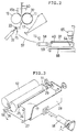
- Figure 1 is a perspective illustration of an embodiment as a whole of the automatic inspection apparatus of fisheyes in resin according to the present invention.
- Figure 2 is a side view of the lower portion of the same apparatus which shows the outline of said embodiment.
- Figure 3 is a perspective view of the rear lower portion of the apparatus embodied as above.
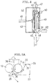
- Figure 4 is a sectional view of the upper portion of said embodiment of the invention.
- FIGS 5A, 5B, 5C and 5D are the outline drawings which show up the operational processes of the foregoing embodiment of this invention.
- Figure 6 is a block diagram of the control circuit of the automatic fisheye inspection apparatus.
- Figures 7A, 7B, 7C and 7D are the flow charts which depict the operational processes of the automatic fisheye inspection apparatus.
- Figure 8 illustrates a modified embodiment of the configuration for pushing the sheet frame against the resin sheet.
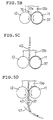
- Figure 9 illustrates a modified embodiment of the sheet frame.
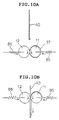
- Figures 10A and 10B show another modified embodiment of the configuration for pushing the sheet frame against the resin sheet.
- Figure 11 represents a modified embodiment of the configuration of the end plate.
- Figure 12 depicts a modified embodiment of the configuration in which the resin compound drooping from under the fine gap between the kneading rolls is returned to the upper portion.
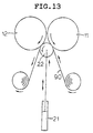
- Figure 13 represents a modified embodiment of the kneading rolls.
- Figure 1 is a perspective view showing the one embodiment as a whole of the sheet manufacturing apparatus for resin inspection to which the present invention is applied.
- This sheet manufacturing apparatus for resin inspection together with the inspection portion as shown in Fig. 2, the cross sectional outline drawing of the essential part, constitutes the automatic fisheye inspection apparatus.
- Fig. 1 the apparatus is assembled on frames 61 and 62 which are symmetric as a whole. Between the frames 61 and 62, a pair of kneading rolls 11 and 12 are axially supported. These kneading rolls, arranged in parallel, come near and opposed to each other forming a valley-like portion therebetween. Provided between these rolls is a photoelectric sensor 76 (refer to Fig. 5B) for resin bank whose detection range is said valley portion.
- the respective rotating shafts of the kneading rolls 11 and 12 are coupled with distinct drive motors and the axial support member of the roll 11 is fixed with the frames 61 and 62, while the both sides of the axial support member for the roll 12 are so screwed into the screw rod connected with motors 13a and 13b that the kneading roll 12 displaces by parallel translation as the motors 13a and 13b rotate to come nearer to or go away from the kneading roll 11.
- the screw rod is provided with indicating pointers 14a and 14b which allow to read out the gap between the rolls 11 and 12 which incorporate high frequency induction coils and are connected with power supply thus enabling to be heated.
- a pair of end plates 15a and 15b regulate the extension of the resin as kneaded by the kneading rolls 11 and 12, and the distance between these plates determines the substantial effective width of the rolls 11 and 12.
- Both end plates 15a and 15b are engaged into a guide bar 9, in a way capable of sliding, and screwed respectively into the screw rods 23a and 23b.
- the screw rod 23a is coupled with a pulse motor 16a while the screw rod 23b with another pulse motor 16b. It is so designed that when the pulse motors 16a and 16b rotate, the end plates 15a and 15b come nearer to, or go away from each other in such a fashion that the substantially effective width of the kneading rolls 11 and 12 should change accordingly.
- an endless belt 17 shown in Fig. 3 is provided at a position not shown here (the other side of Fig. 1).
- the endless belt 17 has a width almost same with the substantial effective width of the kneading rolls 11 and 12, and suspendedly rotated by the shafts 24, 25, 26 and 27 which are rotatably supported by the belt frame 28.
- the shift 24 is rotatably supported by the frames 61 and 62, while the shaft 26 is engaged into the circular arc guide groove 29 on the sides of the frames 61 and 62 whose center is the shaft 24.
- An air cylinder 18 is pivotally mounted on the chassis plate across the frames 61 and 62 so that the cylinder 18 can rotate upward and downward, and the plunger of the cylinder 18 is coupled with the belt frame 28.
- This mechanism makes it possible that by the action of the air cylinder 18, the endless belt 17 advances and retreats together with the belt frame 28 so that the belt can come in contact with or go away from the roll 11. Further mounted on the belt frame 28 and in contact with the surface of the endless belt 17 is a scraper 20 for the belt, and another scraper 19 for roll 12 is mounted on the surface of this roll. Furthermore in the lower portion of the kneading rolls 11 and 12, a cleaning roll 22 coupled with the air cylinder 21 is telescopically mounted so that the roll 22 can advance to and retire from the position in contact with the rolls 11 and 12. A scraper 75 for cleaning roll 22 is provided on this roll.
- a sheet frame supply source 42 is fixed on the frames 61 and 62 through intermediary of a mount 44.
- This supply source 42 whose detailed sectional view is given in Figure 4, lets the sheet frames 40 fall one by one toward the valley-shaped portion delimited by the kneading rolls 11 and 12.
- the major components of the sheet frame supply source 42 are arranged inside the casing 43.
- a partition plate 41 Provided inside the casing 43 is a partition plate 41 the lower portion of which is kept open to let the sheets frames 40 fall freely.
- a great number of cardboard sheet frames 40 are vertically housed against the partition plate 41 where an air cylinder 45 is furnished to hold the sheet frames 40 and the partition plate 41.
- an upper suction cap 46 is instilled so that the cap can move up and down in connection with an air cylinder 47.
- a lower suction cap 48 is arranged which is screwed into the screw rod 49 and engaged with the guide bar. Because the screw rod 49 is coupled with a motor 50, the lower suction cap can move up and down as the motor 50 rotates. Further below the partition plate 41 a stopper 51 is telescopically provided in connection with the air cylinder 52 in such a way that it can advance and retreat with this cylinder.
- a surface displacement meter 53 which comes in contact with the surface of the roll 11 between the end plates 15a and 15b (that is, within the substantial effective width of the roll 11) on the one hand
- another surface displacement meter 54 which comes in contact with the surface of the roll 11 outside the end plates 15a and 15b (that is, outside the substantial effective width of the roll 11), on the other, both in connection with the air cylinder 55.
- the surface displacement meters 53 and 54 having, as measurers, rollers at their tops, can expand and contract pursuant to fine displacement to output electrically the amount of expansion and contraction.
- Figure 2 depicts the inspection portion showing the periphery of the pair of kneading rolls 11 and 12.
- a guide plate 57 is installed below the kneading rolls 11 and 12 of the sheet manufacturing apparatus.
- a photoelectric sensor 71 is provided which detects falling resin compound.
- the guide plate 57 is followed by a belt conveyor 58 in the direct neighborhood of which is installed a photographing device.
- a light source 64 and a video camera 65 are provided respectively in the lower and upper portions of the sheets for inspection 37 and 40 on the set-up table 59 of the sheets for inspection in such a way that the light passing through the sheet 37 can be photographed.
- the set-up table 59 of the sheets for inspection, set on the belt conveyor 66 can travel with the sheets for inspection 37 and 40 as transferred from the belt conveyor 58 within the photographing field of view of the video camera 65 which can accordingly photograph in continuous fashion all the sheets 37 running within the field of view one after another.
- Respectively provided above the belt conveyor 58 and the belt conveyor 66 are sheet No. 1 sensor 72 and sheet No. 2 sensor 73 which detect the sheets for inspection.
- the overall face of the sheet 37 can be photographed also when the set-up table 59 of the sheets for inspection is fixed while the light source 64 and the video camera 65 are made to be movable. The same photographing is possible without this movable mechanism if the video camera 65 is of wide angle field of view with higher resolution.
- the respective drives of the automatic fisheye inspection apparatus as shown in Figures 1 and 2 are so designed as to be controlled by the control circuit 80 shown in fig. 6.
- Linked with this control circuit 80 are: a high frequency power supply for rolls 11 and 12, a driving power supply for motors 13a and 13b, another driving power supply for motors 16a and 16b, a motor drive power supply for rotation of the rolls 11 and 12, the trigger of air cylinder 18, the trigger of air cylinder 55, a driving circuit for sheet frame supply source 42, a power supply for the light source 64, another power supply for the video camera 65, the trigger of air cylinder 21, a driving power supply for conveyor 58, and a driving power supply for conveyor 66.
- a sensor 71 for compound a photoelectric sensor 76 for resin bank
- sheet No. 1 sensor 72 and sheet No. 2 sensor 73 are also connected to this control circuit.
- Step 101 the kneading rolls 11 and 12 are raised to a prescribed temperature by electrifying the high frequency induction coils.
- the motors 13a and 13b shall be started, the values indicated by the pointers 14a and 14b shall be read out to match the gap between the kneading rolls 11 and 12 to the initial setting.
- the motors 16a and 16b shall be started, and the gap between the end plates 15a and 15b shall be matched with the initial setting.
- the drive motors for the rolls 11 and 12 shall be started with the rotational speed R1 of the roll 11 being a little higher than that of the other roll 12, R2, when the air cylinder 55 is made to retreat and the surface displacement meters 53 and 54 are made to be both away from the kneading roll 11.
- the cylinder 18 shall act, and the endless belt 17 shall advance to be in contact with the roll 11, when the endless belt 17 will make its rounds by the frictional drive of the roll 11 which will be turning.
- the sheet frame 40 has been housed in the casing 43 of the sheet frame supply source 42.
- the compound (for example, powdered vinyl chloride resin mixed with a stabilizer and a plasticiser, and if desired, with a coloring agent) for the sample resin to be inspected shall be prepared beforehand.
- Compound 36 as feedstock is introduced from a beaker into the valley-like portion between the kneading rolls 11 and 12 as shown in Figure 5A under Step 106. Most of the compound 36 is molten down and adheres to the roll 11 which is turning at high speed, but a part of the compound, though very little, sticks to the low speed rotating roll 12 and will be scraped off by the scraper 19 for the roll 12 in contact with the roll surface to fall on the endless belt 17. A part of the compound 36 introduced will pass through the fine gap to fall directly on the endless belt 17.
- Step 109 the high speed roll 11 and low speed roll 12 continue to rotate for a prescribed time, the compound goes to be transformed into the sheet 37 on the high rotational roll 11 as shown in Figure 5B.
- Residual resin 37a is formed in the valley-like portion where the high rotational roll 11 meets with the low rotational roll 12.
- This residue which is no other than the so-called "bank,” is detected by the sensor 76, where the resin is cut.
- the pulse motors 16a and 16b are made to rotate at Steps 111 and 113, the end plates 15a and 15b come nearer to or go away from each other, thereby varying the substantial effective width of the kneading rolls 11 and 12. This operation, if repeated, will make the amount of the resin bank 37a appropriate, and completely uniform the kneading of the resin, leading thus to the homogeneous resin sheet for inspection to be manufactured.
- the resin cut shall be terminated.
- the gap between the kneading rolls 11 and 12 shall be matched with a prescribed amount, that is set to the thickness of the resin sheet for inspection to be manufactured by means of the motors 13a and 13b, and at Step 116 the distance between the end plates 15a and 15b shall be matched with prescribed width, that is set to the width of the resin sheet for inspection to be manufactured using the pulse motors 16a and 16b.
- the kneading rolls 11 and 12 shall further continue to rotate for some time, and then the thickness of the sheet 37 formed on the kneading roll 12 shall be measured.
- the air cylinder 55 shown in Figure 1 shall be activated to make both the surface displacement meters 53 and 54 advance, when the roller at the top of the surface displacement meter 53 will come in contact with the surface of the sheet 37 to rotate, and the roller at the top of the surface displacement meter 54 will come into direct contact with the kneading roll 11 to rotate.
- One can know the thickness of the sheet 37 by calculating the difference between the output values of the surface displacement meters 53 and 54.
- Step 118 If the results of this measurement permit to make sure that the thickness of the sheet 37 is desired one (Step 118), then the rolls 11 and 12 shall stop rotating at Step 119. Then at Step 120 the motors 13a and 13b shall rotate for parallel displacement of the kneading roll 12. Then the gap between the kneading rolls 11 and 12 shall be widened into the amount almost same with the thickness of the sheet frame 40, and the distance between the end plates 15a and 15b shall be broadened enough at Step 121 by means of the pulse motors 16a and 16b in such a way that the sheet frame 40 can pass freely therethrough.
- the kneading roll 11 shall rotate by inching (Step 122) to displace downward the bank 37a at the valley portion between the kneading rolls 11 and 12. Under the conditions as shown in Figure 5C the sheet frame 40 will be supplied.
- Step 123 in the flow chart corresponds to Step 123 in the flow chart.
- the shock given by the falling sheet frame 40 will insert the sheet 37 between the angle of the sheet frame 40 and the kneading roll 11 to cut the sheet 37.
- the belt conveyor 58 shall be driven at Step 126.
- the sheets will be carried over from the guide plate 57 onto the belt conveyor 58 to be transferred onto the set-up table 59 of the sheet for inspection.
- the belt conveyor 66 shall be driven (Step 128).
- the light source 64 shall be illuminated, and at Step 130 the sheets for inspection 37 and 40 shall travel on the set-up table 59 by the belt conveyor 66, activating the video camera 65.
- the video camera 65 will photograph the fisheyes in the sheet 37 by the light coming through the sheet 37.
- the number of the fisheyes imaged one after another may be counted with operational circuit and output at the printer to record in memory or else output by a monitor.
- the measurement shall terminate.
- the air cylinder 21 shall be activated at Step 132 to advance the cleaning roll 22 to clean up the surface of the rolls 11 and 12. At the same time the surface of the endless belt 17 shall be cleaned by the scraper 20 for belt.
- Figure 8 represents an exemplary configuration where the sheet frame 40 is pressed against the sheet 37 on the kneading roll 11 by means of push-down pressure against the roll 11 out of the kneading rolls 11 and 12.
- the pushing-down means consists, for instance, of an air cylinder 77 and a pinch roller 78. The sheet, when pushed by the pinch roller 78, adheres to the sheet frame 40 to be evacuated downward.
- Figure 9 depicts another embodiment of the sheet frame 40 which has, at its central portion, a space for light transmission, and a sheet-cutting slit 83 in the vicinity of the edge of one side of the frame perimeter 82.
- the sheet frame 40 may have slanted or curved surface at the edge 82a between the light transmission apace and the perimeter 82, regardless of whether the sheet cutting slit 83 exists.
- the perimeter 82 surface to which the sheet 37 adheres may be applied an adhesive agent.
- Figures 10A and 10B illustrate embodiments of the invention where the kneading rolls 11 and 12 are pushing against each other by an energizing means.
- the energizing means used may, for example, be pressure bar springs 85 and 86. If the sheet frame 40 provided, for instance, with such sheet-cutting slit 83 as shown in Fig. 9 is fed between the kneading rolls 11 and 12, thus pressed against each other by the pressure bar springs 85 and 86, then the sheet 37 on the roll 11 will be cut out by the sheet-cutting slit 83 and adhered to the sheet frame 40 to be evacuated downward.
- FIG. 11 shows an embodiment of the invention where the inner faces of the end plates 15a and 15b are internally curved toward the rotational direction of the kneading roll 11. This configuration makes the kneading of the sheet 37 more through.
- the inner faces of the end plates 15a and 15b may be flat and narrowly slanted.
- Figure 12 represents an embodiment of a device where the resin compound 36 fallen from the fine gap between the kneading rolls 11 and 12 is returned to the valley-formed portion between the same rolls 11 and 12.
- the endless belt 84 is wrapped up with the pulleys 85a, 85b, 85c and 85d, and outside of these another endless belt 86 is wrapped up with the pulleys 87a, 87b, 87c and 87d so that they should surround the former belt 84 and pulleys 85a to 85d and rotate in the reverse direction (direction of the arrow) of the pulleys 85a to 85d.
- the scrapers 89 and 88 come in contact with the lower faces of the upper ends of the endless belt 84 and 86 respectively.
- the resin compound 36 introduced into the valley portion between the kneading rolls 11 and 12 adheres to the kneading roll 11, a part of which however falls from between the fine gap onto the endless belt 86.
- This resin compound 36 is held between the two endless belts 84 and 86 to be transported upward, scraped down by the scrapers 89 and 88, then falls again into the valley between the kneading rolls 11 and 12.
- Figure 13 illustrates an exemplary embodiment of the cleaning roll 22 for cleaning the kneading rolls 11 and 12 (refer to Fig. 1) where the slidably contacting face of the cleaning roller 22 coupled with the air cylinder 21 is covered with the cleaning cloth 90.
- the cleaning cloth 90 is a long strip which is unwound from roll-formed supply source, covers the cleaning roll 22, and then wound up again in roll form, thereby allowing the kneading rolls 11 and 12 always to be in sliding contact with new, clean cloth face.
- the cleaning cloth 90 may be folded in zigzag form on the supply side.
- the automatic in-resin fisheye inspection apparatus allows for any worker, even without any skill whatsoever, to inspect automatically the fisheyes of synthetic resins without resorting to any manpower assistance and any qualification.
Landscapes
- Engineering & Computer Science (AREA)
- Mechanical Engineering (AREA)
- Health & Medical Sciences (AREA)
- Life Sciences & Earth Sciences (AREA)
- Chemical & Material Sciences (AREA)
- Analytical Chemistry (AREA)
- Physics & Mathematics (AREA)
- Biochemistry (AREA)
- General Health & Medical Sciences (AREA)
- General Physics & Mathematics (AREA)
- Immunology (AREA)
- Pathology (AREA)
- Medicinal Chemistry (AREA)
- Food Science & Technology (AREA)
- Textile Engineering (AREA)
- Processing And Handling Of Plastics And Other Materials For Molding In General (AREA)
- Investigating Materials By The Use Of Optical Means Adapted For Particular Applications (AREA)
- Length Measuring Devices By Optical Means (AREA)
Applications Claiming Priority (13)
| Application Number | Priority Date | Filing Date | Title |
|---|---|---|---|
| JP37119/93 | 1993-02-25 | ||
| JP37120/93 | 1993-02-25 | ||
| JP3712093 | 1993-02-25 | ||
| JP5037118A JPH0790549B2 (ja) | 1992-07-02 | 1993-02-25 | 混練装置および落下物返戻装置 |
| JP3711993A JPH0754304B2 (ja) | 1992-06-29 | 1993-02-25 | シート検査装置、型枠、シート検査用サンプル作成装置および型枠送り装置 |
| JP37118/93 | 1993-02-25 | ||
| PCT/JP1993/001491 WO1994019160A1 (fr) | 1993-02-25 | 1993-10-18 | Melangeur et machine de controle pour melanger une feuille |
| WOPCT/JP93/01491 | 1993-10-18 | ||
| JP02128094A JP3169301B2 (ja) | 1994-02-18 | 1994-02-18 | 樹脂中のフィッシュアイ自動検査装置 |
| JP02127994A JP3148879B2 (ja) | 1994-02-18 | 1994-02-18 | 樹脂混練装置、検査用の樹脂シート製造装置、検査用の樹脂シート製造方法 |
| JP21280/94 | 1994-02-18 | ||
| JP21279/94 | 1994-02-18 | ||
| PCT/JP1994/000309 WO1994019680A1 (fr) | 1993-02-25 | 1994-02-25 | Appareil d'inspection automatique d'yeux de poisson dans la resine, appareil et procede de production de feuille de resine pour inspection |
Publications (2)
| Publication Number | Publication Date |
|---|---|
| EP0637745A1 true EP0637745A1 (de) | 1995-02-08 |
| EP0637745A4 EP0637745A4 (de) | 1998-01-14 |
Family
ID=27563933
Family Applications (1)
| Application Number | Title | Priority Date | Filing Date |
|---|---|---|---|
| EP94907691A Withdrawn EP0637745A4 (de) | 1993-02-25 | 1994-02-25 | Automatisches prüfgerät für fischaugen in kunststoff und vorrichtung und methode zur herstellung einer kunststoffolie zur prüfung. |
Country Status (1)
| Country | Link |
|---|---|
| EP (1) | EP0637745A4 (de) |
Cited By (6)
| Publication number | Priority date | Publication date | Assignee | Title |
|---|---|---|---|---|
| AU704204B2 (en) * | 1994-12-15 | 1999-04-15 | Endovascular Technologies, Inc. | Vascular graft and delivery catheter |
| US6461035B2 (en) | 1998-10-13 | 2002-10-08 | Fraunhofer-Gesellschaft Zur Foerderung Der Angewandten Forschung E.V. | Device and method for non-contact detection of structural and/or surface faults in large surface bodies |
| CN103434038A (zh) * | 2013-07-28 | 2013-12-11 | 安徽同丰橡塑工业有限公司 | 一种炼胶机上宽度调节装置 |
| CN107627581A (zh) * | 2017-11-02 | 2018-01-26 | 张家港市兰航机械有限公司 | 挤出机中的橡胶热喂料装置 |
| CN109969692A (zh) * | 2019-04-12 | 2019-07-05 | 烟台海纳制动技术有限公司 | 一种四工位刹车片防错检查装置 |
| CN113176271A (zh) * | 2021-04-27 | 2021-07-27 | 凯多智能科技(上海)有限公司 | 一种纠偏、瑕疵、尺寸检测传感器 |
Family Cites Families (4)
| Publication number | Priority date | Publication date | Assignee | Title |
|---|---|---|---|---|
| US4381447A (en) * | 1980-09-19 | 1983-04-26 | Brandt, Inc. | Method and apparatus for evaluating and sorting sheets in a high speed manner |
| JPS61283532A (ja) * | 1985-06-11 | 1986-12-13 | Dainippon Printing Co Ltd | シ−テイング方法 |
| JPH0213852A (ja) * | 1988-07-01 | 1990-01-18 | Shin Etsu Chem Co Ltd | 塩化ビニル系樹脂用改質剤の品質検査方法 |
| JPH03111761A (ja) * | 1989-09-27 | 1991-05-13 | Dainippon Printing Co Ltd | 検査シート |
-
1994
- 1994-02-25 EP EP94907691A patent/EP0637745A4/de not_active Withdrawn
Cited By (8)
| Publication number | Priority date | Publication date | Assignee | Title |
|---|---|---|---|---|
| AU704204B2 (en) * | 1994-12-15 | 1999-04-15 | Endovascular Technologies, Inc. | Vascular graft and delivery catheter |
| US6461035B2 (en) | 1998-10-13 | 2002-10-08 | Fraunhofer-Gesellschaft Zur Foerderung Der Angewandten Forschung E.V. | Device and method for non-contact detection of structural and/or surface faults in large surface bodies |
| CN103434038A (zh) * | 2013-07-28 | 2013-12-11 | 安徽同丰橡塑工业有限公司 | 一种炼胶机上宽度调节装置 |
| CN107627581A (zh) * | 2017-11-02 | 2018-01-26 | 张家港市兰航机械有限公司 | 挤出机中的橡胶热喂料装置 |
| CN107627581B (zh) * | 2017-11-02 | 2023-11-21 | 张家港市兰航机械有限公司 | 挤出机中的橡胶热喂料装置 |
| CN109969692A (zh) * | 2019-04-12 | 2019-07-05 | 烟台海纳制动技术有限公司 | 一种四工位刹车片防错检查装置 |
| CN113176271A (zh) * | 2021-04-27 | 2021-07-27 | 凯多智能科技(上海)有限公司 | 一种纠偏、瑕疵、尺寸检测传感器 |
| CN113176271B (zh) * | 2021-04-27 | 2022-05-03 | 凯多智能科技(上海)有限公司 | 一种纠偏、瑕疵、尺寸检测传感器 |
Also Published As
| Publication number | Publication date |
|---|---|
| EP0637745A4 (de) | 1998-01-14 |
Similar Documents
| Publication | Publication Date | Title |
|---|---|---|
| DE69717413T2 (de) | Verfahren zur Gewichtsbestimmung von bogenförmigen Trägern | |
| DE3854045T2 (de) | Anordnung zur kontrolle der dicke eines kunststoffbehälters sowie kontrollsystem dafür. | |
| DE3852946T2 (de) | Immuno-Agglutinationsmessgerät. | |
| EP0637745A1 (de) | Automatisches prüfgerät für fischaugen in kunststoff und vorrichtung und methode zur herstellung einer kunststoffolie zur prüfung | |
| US5959737A (en) | Frame feeding apparatus and automatic sheet thickness detection apparatus | |
| US4453406A (en) | Device for the transport of test specimens in strip form to a measuring apparatus | |
| JPH0611634B2 (ja) | 記録装置の紙送り機構 | |
| DE69534270T2 (de) | Blatthantiersystem und -verfahren | |
| KR950025827A (ko) | 전자총의 전극간격 자동 측정장치 | |
| US4550613A (en) | Apparatus for automatic determination of the tensile strength properties of a sheet of paper | |
| DE3318482A1 (de) | Geraet zum messen der dicke von ueberzuegen auf sich kontinuierlich bewegendem material | |
| EP0160488B1 (de) | Verfahren zur Messung der Orientierung von Bestandteilen in Folien | |
| US2951416A (en) | Device for measuring film thickness | |
| JP3074106B2 (ja) | 樹脂チューブとその切断装置及び切断方法 | |
| US5872715A (en) | Automatic inspection and certification system | |
| KR20220026175A (ko) | 청소유닛을 구비한 표면 검사 장치 | |
| EP0610811B1 (de) | Fotografisches Kopier- und Entwicklungsgerät | |
| KR0156018B1 (ko) | 수지중의 피시아이 검사용의 수지시트 제조장치 | |
| JP3169301B2 (ja) | 樹脂中のフィッシュアイ自動検査装置 | |
| WO1994019680A1 (fr) | Appareil d'inspection automatique d'yeux de poisson dans la resine, appareil et procede de production de feuille de resine pour inspection | |
| JP3190723B2 (ja) | ローラ偏心量測定装置 | |
| US3863855A (en) | Film unwinding and splicing apparatus and method | |
| DE3530066C2 (de) | ||
| CN114964897B (zh) | 一种铝板带箔表面铝粉采集装置 | |
| JPS5938805A (ja) | 工作物の長さを調整するための方法及び装置 |
Legal Events
| Date | Code | Title | Description |
|---|---|---|---|
| PUAI | Public reference made under article 153(3) epc to a published international application that has entered the european phase |
Free format text: ORIGINAL CODE: 0009012 |
|
| 17P | Request for examination filed |
Effective date: 19940824 |
|
| AK | Designated contracting states |
Kind code of ref document: A1 Designated state(s): BE DE FR GB IT NL PT |
|
| A4 | Supplementary search report drawn up and despatched |
Effective date: 19971127 |
|
| AK | Designated contracting states |
Kind code of ref document: A4 Designated state(s): BE DE FR GB IT NL PT |
|
| 17Q | First examination report despatched |
Effective date: 20030814 |
|
| GRAP | Despatch of communication of intention to grant a patent |
Free format text: ORIGINAL CODE: EPIDOSNIGR1 |
|
| RTI1 | Title (correction) |
Free format text: THERMOPLASTIC SHEET MANUFACTURING AND INSPECTION APPARATUS |
|
| STAA | Information on the status of an ep patent application or granted ep patent |
Free format text: STATUS: THE APPLICATION IS DEEMED TO BE WITHDRAWN |
|
| 18D | Application deemed to be withdrawn |
Effective date: 20110208 |