EP0160488A2 - Verfahren zur Messung der Orientierung von Bestandteilen in Folien - Google Patents
Verfahren zur Messung der Orientierung von Bestandteilen in Folien Download PDFInfo
- Publication number
- EP0160488A2 EP0160488A2 EP85302811A EP85302811A EP0160488A2 EP 0160488 A2 EP0160488 A2 EP 0160488A2 EP 85302811 A EP85302811 A EP 85302811A EP 85302811 A EP85302811 A EP 85302811A EP 0160488 A2 EP0160488 A2 EP 0160488A2
- Authority
- EP
- European Patent Office
- Prior art keywords
- sheet
- web
- sample portion
- orientation
- set forth
- Prior art date
- Legal status (The legal status is an assumption and is not a legal conclusion. Google has not performed a legal analysis and makes no representation as to the accuracy of the status listed.)
- Granted
Links
- 238000000034 method Methods 0.000 title claims abstract description 35
- 239000000470 constituent Substances 0.000 title claims abstract description 11
- 230000010287 polarization Effects 0.000 claims abstract description 11
- 238000005259 measurement Methods 0.000 claims description 15
- 239000000919 ceramic Substances 0.000 claims description 11
- 238000010521 absorption reaction Methods 0.000 claims description 3
- 230000002441 reversible effect Effects 0.000 description 11
- 230000003287 optical effect Effects 0.000 description 8
- -1 polyethylene Polymers 0.000 description 8
- 238000011144 upstream manufacturing Methods 0.000 description 7
- 238000010586 diagram Methods 0.000 description 5
- 229920000139 polyethylene terephthalate Polymers 0.000 description 5
- 239000005020 polyethylene terephthalate Substances 0.000 description 5
- 230000005856 abnormality Effects 0.000 description 4
- PNEYBMLMFCGWSK-UHFFFAOYSA-N aluminium oxide Inorganic materials [O-2].[O-2].[O-2].[Al+3].[Al+3] PNEYBMLMFCGWSK-UHFFFAOYSA-N 0.000 description 4
- BPQQTUXANYXVAA-UHFFFAOYSA-N Orthosilicate Chemical compound [O-][Si]([O-])([O-])[O-] BPQQTUXANYXVAA-UHFFFAOYSA-N 0.000 description 3
- 230000002238 attenuated effect Effects 0.000 description 3
- 239000010408 film Substances 0.000 description 3
- 238000004519 manufacturing process Methods 0.000 description 3
- 239000000463 material Substances 0.000 description 3
- 239000002985 plastic film Substances 0.000 description 3
- 238000010345 tape casting Methods 0.000 description 3
- 239000004698 Polyethylene Substances 0.000 description 2
- 229920000573 polyethylene Polymers 0.000 description 2
- 238000007711 solidification Methods 0.000 description 2
- 230000008023 solidification Effects 0.000 description 2
- 239000010409 thin film Substances 0.000 description 2
- 239000002033 PVDF binder Substances 0.000 description 1
- 229930040373 Paraformaldehyde Natural products 0.000 description 1
- 239000004952 Polyamide Substances 0.000 description 1
- 239000004642 Polyimide Substances 0.000 description 1
- VRDIULHPQTYCLN-UHFFFAOYSA-N Prothionamide Chemical compound CCCC1=CC(C(N)=S)=CC=N1 VRDIULHPQTYCLN-UHFFFAOYSA-N 0.000 description 1
- 239000004809 Teflon Substances 0.000 description 1
- 229920006362 Teflon® Polymers 0.000 description 1
- GWEVSGVZZGPLCZ-UHFFFAOYSA-N Titan oxide Chemical compound O=[Ti]=O GWEVSGVZZGPLCZ-UHFFFAOYSA-N 0.000 description 1
- 238000002441 X-ray diffraction Methods 0.000 description 1
- JRPBQTZRNDNNOP-UHFFFAOYSA-N barium titanate Chemical compound [Ba+2].[Ba+2].[O-][Ti]([O-])([O-])[O-] JRPBQTZRNDNNOP-UHFFFAOYSA-N 0.000 description 1
- 229910002113 barium titanate Inorganic materials 0.000 description 1
- 239000011230 binding agent Substances 0.000 description 1
- 239000003990 capacitor Substances 0.000 description 1
- 239000003985 ceramic capacitor Substances 0.000 description 1
- 238000001816 cooling Methods 0.000 description 1
- 229920001577 copolymer Polymers 0.000 description 1
- 230000007423 decrease Effects 0.000 description 1
- 238000009826 distribution Methods 0.000 description 1
- 239000000835 fiber Substances 0.000 description 1
- 238000010030 laminating Methods 0.000 description 1
- 239000000314 lubricant Substances 0.000 description 1
- 239000000155 melt Substances 0.000 description 1
- 238000002844 melting Methods 0.000 description 1
- 230000008018 melting Effects 0.000 description 1
- 230000000704 physical effect Effects 0.000 description 1
- 229920006255 plastic film Polymers 0.000 description 1
- 229920002647 polyamide Polymers 0.000 description 1
- 229920001721 polyimide Polymers 0.000 description 1
- 229920000642 polymer Polymers 0.000 description 1
- 229920006324 polyoxymethylene Polymers 0.000 description 1
- 229920000915 polyvinyl chloride Polymers 0.000 description 1
- 239000004800 polyvinyl chloride Substances 0.000 description 1
- 229920002981 polyvinylidene fluoride Polymers 0.000 description 1
- 239000000843 powder Substances 0.000 description 1
- 230000008707 rearrangement Effects 0.000 description 1
- HBMJWWWQQXIZIP-UHFFFAOYSA-N silicon carbide Chemical compound [Si+]#[C-] HBMJWWWQQXIZIP-UHFFFAOYSA-N 0.000 description 1
- 229910010271 silicon carbide Inorganic materials 0.000 description 1
- VEALVRVVWBQVSL-UHFFFAOYSA-N strontium titanate Chemical compound [Sr+2].[O-][Ti]([O-])=O VEALVRVVWBQVSL-UHFFFAOYSA-N 0.000 description 1
- 230000001360 synchronised effect Effects 0.000 description 1
- 229920001187 thermosetting polymer Polymers 0.000 description 1
- OGIDPMRJRNCKJF-UHFFFAOYSA-N titanium oxide Inorganic materials [Ti]=O OGIDPMRJRNCKJF-UHFFFAOYSA-N 0.000 description 1
- XLYOFNOQVPJJNP-UHFFFAOYSA-N water Substances O XLYOFNOQVPJJNP-UHFFFAOYSA-N 0.000 description 1
Images


Classifications
-
- G—PHYSICS
- G01—MEASURING; TESTING
- G01N—INVESTIGATING OR ANALYSING MATERIALS BY DETERMINING THEIR CHEMICAL OR PHYSICAL PROPERTIES
- G01N22/00—Investigating or analysing materials by the use of microwaves or radio waves, i.e. electromagnetic waves with a wavelength of one millimetre or more
- G01N22/02—Investigating the presence of flaws
Definitions
- the present invention relates to a method and apparatus for measuring the molecular orientation of webs or sheets.
- a non-stretched sheet is produced either by the tubular film process in which the sheet material is first heated or friction- melted to be given fluidity and then extruded into a cylindrical form, into which air is blown to inflate it and at the same time it is externally cooled for solidification or by the T-die process in which the melt is extruded into a smooth thin film form and then cooled for solidification in a water tank or on a cooling drum.
- such non-stretched sheet is too inferior in such mechanical strengths as tensile strength, impact strength and tear strength and in processability to be used as such.
- the non-stretched sheet is heated to a suitable temperature above its softening point or below its melting point and subjected to uniaxial or biaxial stretching to improve its physical properties.
- uniaxial or biaxial stretching it does not necessarily follow that simply mechanically stretching the non-stretched sheet provides a sheet of good quality, but it is necessary . that the stretching be performed to provide a particular orientation of molecules to agree with the intended use of the sheet product.
- a fine ceramic powder is mixed with a binding agent and a lubricant to produce a slip, which is then poured onto a continuously traveling tape of polyethylene or Teflon, and after the thickness of the slip layer on the tape is adjusted as by a doctor, it is fired and finished, the process being called the tape casting forming method, whereby a ceramic sheet in thin film form is obtained.
- Such thin film-like ceramic sheets are used as a material for laminated ceramic capacitors, for example, by laminating them alternately with electrodes.
- polarized microwaves (hereinafter referred to as lineally polarized waves) are applied, at right angles, to the sheet surface while relatively rotating the sheet in its plane, the amount of attenuation increases or decreases with the rotative angle and that the angle at which the maximum amount of attenuation is exhibited coincides with the direction of orientation of fibers or molecules.
- the present invention intended to achieve the aforesaid object, provides a method and apparatus for measuring the orientation of the constituents of web or sheet products by using a cavity resonator composed of a pair of waveguides having in their bottoms a transmitting antenna and a receiving antenna, respectively, and opposed at their openings to each other with a small clearance defined therebetween, said method comprising the steps of:
- orientation to be measured is generally the molecular orientation of said web or sheet.
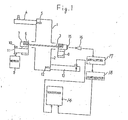
- Fig. 1 schematically shows an embodiment of an apparatus used in the sheet orientation measuring method according to the invention.
- the numeral .4 denotes an oscillator which emits linearly polarized microwaves of .3 GHz, for example.
- the microwaves are emitted from an emitting antenna 5 so that they fall on the surface of a sheet 3 always at right angles thereto.
- microwaves which are usable are in the range of hundreds of MHz to 100 GHz, but since attenuation due to the rearrangement of the molecules of sheets takes place more readily in the vicinity of 3- 5 GHz, it is more preferable to use microwaves of about 1-50 GHz'including that portion.
- plastic sheets such as are made of polyethylene, polyoxymethylene, polyvinyl chloride, polyvinylidene fluoride, polyethylene terephthalate, polyamides, polyimides, or copolymers of their and other polymers
- ceramic sheets such as are made of alumina, alumina silicate, barium titanate, titanium oxide, silicon carbide, or strontium titanate.
- microwaves tend to be attenuated more strongly when molecules have polarity
- those of said sheets which have polar groups in their molecules can be efficiently measured.
- those in the form of circles or quadrangles larger than the flange of an upper waveguide 1 are used.
- a sheet fixing block 7 or the like having a keep ring plate 6 in the upper groove section is installed.
- a drive belt 11 is entrained in a belt drive groove 8 formed in the lateral lower portion of the sheet fixing block 7 and in a groove in a drive pulley 10 and a variable speed motor 9 is driven.
- the linearly polarized microwaves attenuated by the molecules in the sheet 3 are received by a receiving antenna 12 after they have passed through the lower waveguide 2, and then they are converted into electric signals. Such electric signals are demodulated by a detector 13 and then recorded by a recorder 14.
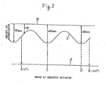
- the detected output curve recorded on the chart in the recorder is as shown at X in Fig.. 2.
- a narrow reflecting tape 15 is applied to a place on the lateral surface of the sheet fixing block 7 so that variations in reflectance of monitor light are detected during rotation by an optical sensor 16 and the resulting electric signals are transferred via an amplifier 17 and a comparator 18 to the recorder 14, whereby they are recorded on the chart as shown at Y in Fig. 2.
- the sheet 3 when attached to the sheet fixing block 7, is positioned so that for example the upstream side of the longitudinal direction is the direction of the reflecting tape 15.
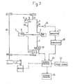
- FIG. 3 An embodiment shown in Fig. 3 is the same as that shown in Fig. 1 in that the sheet 3 is fixed on the sheet fixing block 7 by the keep ring plate 6 and is held between the upper and lower waveguides 1 and 2, but it differs in that. the waveguides 1 and 2 can be rotated while the sheet 3 is kept fixed without being rotated.
- the synchronous rotation of the upper and lower waveguides 1 and 2 is achieved, as shown in Fig. 3, by connecting a reversible motor 19, a drive shaft 20, and waveguide main shafts 21 and 22 by means of belts.
- the angle of rotation of the waveguides be set at a value greater than the angle of 180° needed for measurement, and the initial waiting angle and the next waiting angle can be defined by installing optical sensors, limit switches or the like for detecting the angles, at suitable positions.
- Fig. 3 shows the method of rotating the waveguides by using pulleys and belts, depending upon the objective there may be employed a method of directly rotating the plane of linear polarization as by connecting separate electric motors directly to the ends of the waveguides or applying a magnetic field to the upper waveguide.
- narrow reflecting tapes 24 and 25 are applied, 180° apart, to two places on the lateral surface of the upper waveguide 1 so that variations in reflectance of monitor light are detected during rotation by an optical sensor 16 and the resulting electric signals are transferred via an amplifier 17 and a comparator 18 to a control section 23.
- the sheet 3 when attached to the sheet fixing block 7, is positioned so that for example the upstream side of the longitudinal direction is the direction of the reflecting tape 24.
- Measurement is started when a measurement start signal enters the control section 23.
- the control section 23 on the basis of a program inputted there into in advance, emits a forward rotation start signal to the reversible motor 19, so that the two waveguids 1 and 2 start rotating in the forward direction from the initial waiting angle.
- the control section 23 soon receives from the optical sensor 16 a signal indicating that the reflecting tape 24 has passed by, and it stores this signal as the measurement start angle and thereafter it also receives a signal notifying the passage of the reflecting tape 25 and stores this signal as the measurement termination angle and emits an operation stop signal to the reversible- motor 19, stopping the waveguides 1 and 2 at the next waiting angle.
- the control section 23 computes the received resonance output values corresponding to the individual angles of roiation inputted thereinto from the detector 13 during the internal from measurement start angle to measurement stop angle, and according to the need it delivers its output to a display section 26 such as a CRT or an X-Y plotter.
- the sample on the sheet fixing block 7 is exchanged and a measurement start signal 27 is inputted again.
- the control section 23 gives a reverse rotation command to the reversible motor 19, causing the waveguides 1 and 2 to follow the course which is reverse to the previous one, so that the waveguides 1 and 2 are brought back to the initial waiting angle. Thereafter, the aforesaid procedure is repeated a predetermined number of times.
- the reverse rotation too, the same computing operation is performed and the result is outputted to the display section 26.
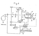
- Fig. 4 shows an embodiment of the invention wherein to observe two-dimensional molecular orientation characteristics of sheets, a narrow sample is taken in the flow direction or width direction from the sheet roll wound up at the reel part and the apparatus of the invention is applied to such sample.
- the polarization plane rotating mechanism and the detecting means using an optical sensor are the same as those shown in Fig. 3.
- a sheet roll 28 of narrow sample is unwound from an unillustrated reel stand and passed over a guide roll 29 and through the nip of sheet feed nip rolls -30.
- Such sheet feed nip rolls 30 are driven by a variable speed motor 9. Further, its operation and stoppage are optionally set by signals from the control section 23.
- the rotative speed of the reversible motor 19 is set to rotate the waveguides 1 and 2 at a required rotative speed, while the amount of rotation and measurement-intended stop time of the sheet feed motor 9 are set to feed the sheet 3 at a required speed.
- the reflecting tape 24 for the waveguide 1 is set at the initial waiting angle, while the emitting antenna 5 is emitting linearly polarized waves.
- the control section emits an operation stop signal to the sheet feed motor 9 and at the same time it emits a forward rotation start signal to the reversible motor 19, . which thereby rotates the waveguides 1 and 2 in the forward direction from the initial waiting angle.
- a forward rotation stop signal is emitted to the reversible motor 19, and the waveguides 1 and 2 are stopped at the next waiting angle.
- the control section 23 stores or memorizes as the first-time measured values the amounts of attenuation corresponding to the individual angles in 180" from the amounts of attenuation received by the receiving antenna 12.
- the control section 23 again operates the sheet feed motor 9 to feed the sheet 3 and stop the second-time measurement place at the middle between the waveguides 1 and 2, while emitting a backward rotation start signal to the reversible motor 19.
- the waveguides 1 and 2 are reversely rotated from the waiting angle and the amounts of attenuation corresponding to the individual ' angles in 180° are stored as the second-time measured values.
- the same procedures as the above are repeated and the results are computed and outputted to a display section 26 such as a printer, X-Y plotter, or the like.
- a 70- ⁇ m thick polyethylene terephthalate sheet sample obtained by stretching with a tenter-method biaxial stretching apparatus was measured by a molecular orientation measuring apparatus constructed in the manner shown in Fig. 1 used in the present invention.
- the waveguides 1 and 2 used were in the form of a rectangle with an opening size of 58.1 mm x 29.1 mm.
- the upstream side of longitudinal direction of said sample was made the direction of the reflecting tape 15 and then the sample was measured using linearly polarized waves of 3.5 GHz while rotating it at 6 rpm.
- a graph was obtained in which the amount of attenuation for each angle was represented by the distance from the origin, as shown in Fig. 5. As is clear from Fig.
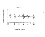
- a 5-m wide polyethylene terephthalate sheet obtained under the same conditions as in Example t was slit along the direction of flow into 10 equal strips to provide elongated samples. Such samples were measured by a molecular orientation measuring apparatus constructed in the manner shown in Fig. 4. A feed rate of 200mm/pitch, a stop time of 1 second, and a rotative speed of the reversible motor 19 to provide a waveguide rotative speed of 10 rpm were set in the control section 23.
- Fig. 6 schematically illustrates the molecular orientations in the 10 slit strips.
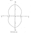
- a 200- ⁇ m thick alumina silicate sample obtained by the tape casting forming method was measured by the apparatus of the invention constructed in the manner shown in Fig. 3.
- Waveguides 1 and 2 having the same size and shape as those used in Example 1 were used, and the upstream side of longitudinal direction of said sample was made the direction of the reflecting tape 24 and then the sample was measured using linearly polarized waves of 3.5 GHz while rotating the waveguides 1 and 2 at a rotative speed of 30 rpm.
- a graph as shown in Fig. 7 was obtained in which the amount of attenuation for each angle is represented by the distance from the origin.
- the direction in which the amount of attenuation is at a maximum coincides with the upward or downward direction of the sample, in the sample in this example it was readily ascertained that the molecular orientation is of longitudinal direction.
- Fig. 8 shows the embodiment of a biaxial stretching and tentering apparatus incorporating the device 32 of the invention therein as an in-line system.
- the sheet 3 is preheated on a preheating roll 34 and passed through a stretching roll 35 which rotates at higher circumferential speed than that of the upstream portion.
- the sheet 3 is passed through a preheating zone 37 of a tentering part 36 to a stretching zone where the sheet 3 is widthwise stretched by clipping.
- the sheet is passed through a thermoset zone 39 where the temperature of the sheet falls, and wound up again into a winder roll 40.
- the molecular orientation measuring device 32 of the invention is placed between the stretching roll 35 and the tentering part 36 as shown in Fig. 8.
- the device can be placed between the tentering part 36 and the winder roll 40 to measure the molecular orientation of the sheet. It is noted in either of the two cases that the operator can observe the stretched result of the sheet to produce the highest grade of it.
- the device 32 according to the invention may be of course fixedly placed at one or more positions within a traversal line of the sheet to achieve the orientation measuring at one or more (series of) spots.
- the device according to the invention may be mounted to a scanning frame or the like mechanism to achieve the orientation measuring in the scan of the frame, discretely or continuously.
Landscapes
- Physics & Mathematics (AREA)
- Biochemistry (AREA)
- Health & Medical Sciences (AREA)
- Life Sciences & Earth Sciences (AREA)
- Chemical & Material Sciences (AREA)
- Analytical Chemistry (AREA)
- Electromagnetism (AREA)
- General Health & Medical Sciences (AREA)
- General Physics & Mathematics (AREA)
- Immunology (AREA)
- Pathology (AREA)
- Investigating Or Analysing Materials By Optical Means (AREA)
- Shaping By String And By Release Of Stress In Plastics And The Like (AREA)
- Manufacturing Of Magnetic Record Carriers (AREA)
Applications Claiming Priority (2)
| Application Number | Priority Date | Filing Date | Title |
|---|---|---|---|
| JP84916/84 | 1984-04-25 | ||
| JP8491684A JPS60227156A (ja) | 1984-04-25 | 1984-04-25 | シ−トの配向性測定方法 |
Publications (3)
| Publication Number | Publication Date |
|---|---|
| EP0160488A2 true EP0160488A2 (de) | 1985-11-06 |
| EP0160488A3 EP0160488A3 (en) | 1988-03-16 |
| EP0160488B1 EP0160488B1 (de) | 1991-06-12 |
Family
ID=13844040
Family Applications (1)
| Application Number | Title | Priority Date | Filing Date |
|---|---|---|---|
| EP19850302811 Expired EP0160488B1 (de) | 1984-04-25 | 1985-04-22 | Verfahren zur Messung der Orientierung von Bestandteilen in Folien |
Country Status (3)
| Country | Link |
|---|---|
| EP (1) | EP0160488B1 (de) |
| JP (1) | JPS60227156A (de) |
| DE (1) | DE3583179D1 (de) |
Cited By (8)
| Publication number | Priority date | Publication date | Assignee | Title |
|---|---|---|---|---|
| EP0176889A3 (de) * | 1984-09-22 | 1989-02-01 | Kanzaki Paper Manufacturing Co., Ltd | Verfahren zur Messung des Orientierungsgrades oder dielektrischer Eigenschaften von dielektrischen Schichten oder Bändern |
| WO1990009578A1 (en) * | 1989-02-14 | 1990-08-23 | Commonwealth Scientific And Industrial Research Organisation | Microwave scanning apparatus |
| US5619143A (en) * | 1989-02-14 | 1997-04-08 | Commonwealth Scientific And Industrial Research Organisation | Microwave scanning apparatus |
| EP0745473A3 (de) * | 1995-05-29 | 1998-03-25 | Toyo Boseki Kabushiki Kaisha | Orientierte Folie aus Polystyren mit isotaktischer Konfiguration |
| WO2011020021A1 (en) * | 2009-08-14 | 2011-02-17 | Rundquist Victor F | Microwave furnace |
| US7894765B2 (en) * | 2006-12-18 | 2011-02-22 | Canon Kabushiki Kaisha | Sheet processing apparatus and image forming apparatus for controlling a folding operation |
| US9253826B2 (en) | 2007-04-26 | 2016-02-02 | Southwire Company, Llc | Microwave furnace |
| US9258852B2 (en) | 2007-04-26 | 2016-02-09 | Southwire Company, Llc | Microwave furnace |
Families Citing this family (3)
| Publication number | Priority date | Publication date | Assignee | Title |
|---|---|---|---|---|
| JPH0781988B2 (ja) * | 1986-02-28 | 1995-09-06 | 新王子製紙株式会社 | シート状試料の磁気的異方性測定方法 |
| US6997325B2 (en) * | 2002-11-13 | 2006-02-14 | M-I L.L.C. | System and process for break detection in porous elements for screening or filtering |
| CN104460062B (zh) * | 2014-12-12 | 2018-09-18 | 深圳市华星光电技术有限公司 | 一种光配向特性检测方法、装置及系统 |
Family Cites Families (3)
| Publication number | Priority date | Publication date | Assignee | Title |
|---|---|---|---|---|
| US3103627A (en) * | 1960-05-18 | 1963-09-10 | Polarad Electronics Corp | Microwave transmission molecular identification system employing wave propagation mode detectors |
| US3254298A (en) * | 1963-09-09 | 1966-05-31 | Burroughs Corp | Instrument for measurement of thin magnetic film parameters |
| FI45799C (fi) * | 1971-03-23 | 1972-09-11 | Valmet Oy | Menetelmä paperin tai vastaavan kuituorientaation määräämiseksi paperi sta heijastuneen valon avulla. |
-
1984
- 1984-04-25 JP JP8491684A patent/JPS60227156A/ja active Granted
-
1985
- 1985-04-22 EP EP19850302811 patent/EP0160488B1/de not_active Expired
- 1985-04-22 DE DE8585302811T patent/DE3583179D1/de not_active Expired - Lifetime
Cited By (9)
| Publication number | Priority date | Publication date | Assignee | Title |
|---|---|---|---|---|
| EP0176889A3 (de) * | 1984-09-22 | 1989-02-01 | Kanzaki Paper Manufacturing Co., Ltd | Verfahren zur Messung des Orientierungsgrades oder dielektrischer Eigenschaften von dielektrischen Schichten oder Bändern |
| WO1990009578A1 (en) * | 1989-02-14 | 1990-08-23 | Commonwealth Scientific And Industrial Research Organisation | Microwave scanning apparatus |
| US5619143A (en) * | 1989-02-14 | 1997-04-08 | Commonwealth Scientific And Industrial Research Organisation | Microwave scanning apparatus |
| EP0745473A3 (de) * | 1995-05-29 | 1998-03-25 | Toyo Boseki Kabushiki Kaisha | Orientierte Folie aus Polystyren mit isotaktischer Konfiguration |
| US7894765B2 (en) * | 2006-12-18 | 2011-02-22 | Canon Kabushiki Kaisha | Sheet processing apparatus and image forming apparatus for controlling a folding operation |
| US8357885B2 (en) | 2007-04-26 | 2013-01-22 | Southwire Company | Microwave furnace |
| US9253826B2 (en) | 2007-04-26 | 2016-02-02 | Southwire Company, Llc | Microwave furnace |
| US9258852B2 (en) | 2007-04-26 | 2016-02-09 | Southwire Company, Llc | Microwave furnace |
| WO2011020021A1 (en) * | 2009-08-14 | 2011-02-17 | Rundquist Victor F | Microwave furnace |
Also Published As
| Publication number | Publication date |
|---|---|
| JPS60227156A (ja) | 1985-11-12 |
| EP0160488B1 (de) | 1991-06-12 |
| EP0160488A3 (en) | 1988-03-16 |
| DE3583179D1 (de) | 1991-07-18 |
| JPH0157730B2 (de) | 1989-12-07 |
Similar Documents
| Publication | Publication Date | Title |
|---|---|---|
| US4581575A (en) | Method and apparatus for measuring orientation of constituents of webs or sheets | |
| US4710700A (en) | Method of measuring orientation or dielectric characteristic of dielectric sheets or webs | |
| EP0160488B1 (de) | Verfahren zur Messung der Orientierung von Bestandteilen in Folien | |
| EP0429161A1 (de) | Walzenknetstärke-Überwachungsverfahren und -vorrichtung, Folienherstellungsverfahren und -vorrichtung und Folientemperaturmessverfahren und -vorrichtung | |
| EP0875359A2 (de) | Anlage zur Herstellung einer orientierten Folie und Verfahren zum Messen der Doppelbrechung | |
| US5991047A (en) | Method for continuously controlling the shrinkage of an amorphous film, and an arrangement herefor | |
| US4857749A (en) | Apparatus and method for measuring the spacing between the cords of a fabric | |
| EP0177011B1 (de) | Verfahren zur Messung der Orientierung von blatt- und stoffähnlichen Materialien | |
| US4982104A (en) | Web drive control apparatus | |
| US3992107A (en) | Automatic flat width control | |
| US4684487A (en) | Process for the control of process parameters in the production of stretched foils | |
| JPS6278255A (ja) | 織物製品の線形素材連続測定装置 | |
| JP2628516B2 (ja) | シート厚みの計測装置 | |
| JPH0143637Y2 (de) | ||
| EP0637745A1 (de) | Automatisches prüfgerät für fischaugen in kunststoff und vorrichtung und methode zur herstellung einer kunststoffolie zur prüfung | |
| JPH1123492A (ja) | 測定装置 | |
| JP2972511B2 (ja) | レーザーによる発泡ポリエチレンシートの厚さ測定方法 | |
| JPH05126652A (ja) | 非接触張力測定装置 | |
| JPH04216922A (ja) | フィルム・シートの配向度インライン計測装置 | |
| KR0145445B1 (ko) | 배향도 측정장치 및 이를 사용한 코팅필름의 제조방법 | |
| JPH05293884A (ja) | 高分子延伸制御装置 | |
| JP3619977B2 (ja) | 検査装置性能評価用走行装置 | |
| JPH0465222A (ja) | フィルム・シートの配向度インライン計測装置 | |
| JPH0650912A (ja) | 高周波によるシート状材料の異方性測定装置 | |
| JP4000789B2 (ja) | 配向測定装置 |
Legal Events
| Date | Code | Title | Description |
|---|---|---|---|
| PUAI | Public reference made under article 153(3) epc to a published international application that has entered the european phase |
Free format text: ORIGINAL CODE: 0009012 |
|
| AK | Designated contracting states |
Designated state(s): DE FR GB SE |
|
| PUAL | Search report despatched |
Free format text: ORIGINAL CODE: 0009013 |
|
| RHK1 | Main classification (correction) |
Ipc: G01N 22/00 |
|
| AK | Designated contracting states |
Kind code of ref document: A3 Designated state(s): DE FR GB SE |
|
| 17P | Request for examination filed |
Effective date: 19880418 |
|
| 17Q | First examination report despatched |
Effective date: 19900817 |
|
| GRAA | (expected) grant |
Free format text: ORIGINAL CODE: 0009210 |
|
| AK | Designated contracting states |
Kind code of ref document: B1 Designated state(s): DE FR GB SE |
|
| ET | Fr: translation filed | ||
| REF | Corresponds to: |
Ref document number: 3583179 Country of ref document: DE Date of ref document: 19910718 |
|
| PLBE | No opposition filed within time limit |
Free format text: ORIGINAL CODE: 0009261 |
|
| STAA | Information on the status of an ep patent application or granted ep patent |
Free format text: STATUS: NO OPPOSITION FILED WITHIN TIME LIMIT |
|
| PG25 | Lapsed in a contracting state [announced via postgrant information from national office to epo] |
Ref country code: GB Effective date: 19920422 |
|
| PG25 | Lapsed in a contracting state [announced via postgrant information from national office to epo] |
Ref country code: SE Effective date: 19920423 |
|
| 26N | No opposition filed | ||
| GBPC | Gb: european patent ceased through non-payment of renewal fee | ||
| PG25 | Lapsed in a contracting state [announced via postgrant information from national office to epo] |
Ref country code: FR Effective date: 19921230 |
|
| REG | Reference to a national code |
Ref country code: FR Ref legal event code: ST |
|
| EUG | Se: european patent has lapsed |
Ref document number: 85302811.6 Effective date: 19921108 |
|
| PGFP | Annual fee paid to national office [announced via postgrant information from national office to epo] |
Ref country code: DE Payment date: 19990430 Year of fee payment: 15 |
|
| PG25 | Lapsed in a contracting state [announced via postgrant information from national office to epo] |
Ref country code: DE Free format text: LAPSE BECAUSE OF NON-PAYMENT OF DUE FEES Effective date: 20010201 |