EP0636890B1 - Verfahren zum Vergleich von Frequenzspektren - Google Patents
Verfahren zum Vergleich von Frequenzspektren Download PDFInfo
- Publication number
- EP0636890B1 EP0636890B1 EP94111231A EP94111231A EP0636890B1 EP 0636890 B1 EP0636890 B1 EP 0636890B1 EP 94111231 A EP94111231 A EP 94111231A EP 94111231 A EP94111231 A EP 94111231A EP 0636890 B1 EP0636890 B1 EP 0636890B1
- Authority
- EP
- European Patent Office
- Prior art keywords
- detecting
- frequency
- partial discharge
- power cable
- insulation
- Prior art date
- Legal status (The legal status is an assumption and is not a legal conclusion. Google has not performed a legal analysis and makes no representation as to the accuracy of the status listed.)
- Expired - Lifetime
Links
Images


Classifications
-
- G—PHYSICS
- G01—MEASURING; TESTING
- G01R—MEASURING ELECTRIC VARIABLES; MEASURING MAGNETIC VARIABLES
- G01R31/00—Arrangements for testing electric properties; Arrangements for locating electric faults; Arrangements for electrical testing characterised by what is being tested not provided for elsewhere
- G01R31/08—Locating faults in cables, transmission lines, or networks
- G01R31/081—Locating faults in cables, transmission lines, or networks according to type of conductors
- G01R31/083—Locating faults in cables, transmission lines, or networks according to type of conductors in cables, e.g. underground
-
- G—PHYSICS
- G01—MEASURING; TESTING
- G01R—MEASURING ELECTRIC VARIABLES; MEASURING MAGNETIC VARIABLES
- G01R31/00—Arrangements for testing electric properties; Arrangements for locating electric faults; Arrangements for electrical testing characterised by what is being tested not provided for elsewhere
- G01R31/12—Testing dielectric strength or breakdown voltage ; Testing or monitoring effectiveness or level of insulation, e.g. of a cable or of an apparatus, for example using partial discharge measurements; Electrostatic testing
- G01R31/1227—Testing dielectric strength or breakdown voltage ; Testing or monitoring effectiveness or level of insulation, e.g. of a cable or of an apparatus, for example using partial discharge measurements; Electrostatic testing of components, parts or materials
- G01R31/1263—Testing dielectric strength or breakdown voltage ; Testing or monitoring effectiveness or level of insulation, e.g. of a cable or of an apparatus, for example using partial discharge measurements; Electrostatic testing of components, parts or materials of solid or fluid materials, e.g. insulation films, bulk material; of semiconductors or LV electronic components or parts; of cable, line or wire insulation
- G01R31/1272—Testing dielectric strength or breakdown voltage ; Testing or monitoring effectiveness or level of insulation, e.g. of a cable or of an apparatus, for example using partial discharge measurements; Electrostatic testing of components, parts or materials of solid or fluid materials, e.g. insulation films, bulk material; of semiconductors or LV electronic components or parts; of cable, line or wire insulation of cable, line or wire insulation, e.g. using partial discharge measurements
-
- G—PHYSICS
- G01—MEASURING; TESTING
- G01R—MEASURING ELECTRIC VARIABLES; MEASURING MAGNETIC VARIABLES
- G01R31/00—Arrangements for testing electric properties; Arrangements for locating electric faults; Arrangements for electrical testing characterised by what is being tested not provided for elsewhere
- G01R31/50—Testing of electric apparatus, lines, cables or components for short-circuits, continuity, leakage current or incorrect line connections
- G01R31/58—Testing of lines, cables or conductors
Definitions
- This invention relates to a method for determining a frequency to detect partial discharge in an insolation of an electric apparatus.
- An electric power cable system comprises a plurality of electric power cables which are connected to provide power cable lines by normal joints, insulating joints, etc., wherein the power cable lines are connected through terminal joints at both ends to high voltage conductors.
- Each of the power cables comprises, for instance, an electric conductor, an inner semi-conductive layer provided around the electric conductor, an insulation provided around the semi-conductive layer to insulate the electric conductor, an outer semi-conductive layer provided around the insulation, a metal sheath provided around the outer semi-conductive layer, and an anti-corrosion layer of poly-vinyl chloride provided around the metal sheath.
- the metal sheath is connected, typically, at the normal joints, the terminal joints, etc. to the ground by lead wires.
- a high voltage applied to the power cable system is turned off to stop operation thereof, and a detecting impedance is inserted into a selected one of the lead wires connecting the metal sheaths to the ground. Furthermore, an apparatus for detecting the partial discharge is connected to both terminals of the detecting impedance. Then, a predetermined high voltage is applied to the electric conductor of the power cable, so that the partial discharge occurs at deteriorating or defect portions of the insulation, thereby generating a high frequency pulse therein. This high frequency pulse induces a high frequency current flowing through the lead wire, so that an electric potential difference is generated across the both terminals of the detecting impedance. The electric potential difference is detected in the partial discharge detecting apparatus to diagnose the deterioration of the insulation.
- the detecting impedance is inserted between a coupling capacitor, which is connected to the high voltage conductor connected through the terminal joint to the electric conductor of the power cable, and the ground, and the apparatus for detecting the partial discharge is connected to the both terminals of the detecting impedance.
- the partial discharge is detected in the same manner as described in the former method.
- the conventional method for detecting partial discharge in an insulation of an electric power cable has a first disadvantage in that the reliance of the electric power cable system is lowered, because the selected lead wire is removed to insert the detecting impedance between the metal sheath and the ground, and an original state is restored, after the partial discharge detecting procedure is over. Furthermore, second and third disadvantages are observed in that operation of the power cable system is interrupted as described before, and in that the detecting operation is troublesome, because the insertion of the coupling capacitor is inevitable. In addition, there is a fourth disadvantage in that the high frequency pulse is attenuated to be propagated to the coupling capacitor in the latter method, and the coupling capacitor must withstand a high voltage.
- fifth to seventh disadvantages are found in that a high detecting sensitivity of the high frequency pulse is not obtained, because the power cable is exposed to external noise, and an overall capacitance of the power cable is large, in that a S/N ratio is lowered, where a measuring frequency is coincident with a frequency at which a noise level is high, and in that a calibration of the apparatus for detecting the partial discharge is difficult in operation, where the partial discharge is detected at the normal joints, the insulating joints, the cable insulation, etc. which are remote from the terminal joints, because a calibration pulse is applied to the high voltage conductor connected to the electric conductor of the power cable.
- the document DE 31 48 735 A1 discloses a method of frequency analysis in which in the harmonic parts of the spectrum are determined.
- the signal spectrum is compared or correlated, respectively, to a reference spectrum, the spectral values thereof beeing associated to the logarithm of frequencies. From the shift in the correlation maximum, the basic frequency can be determined.
- This method a applicable in particular for the analysis of machine noises.
- EP 0 180 322 A2 describes a partial discharge measuring device which intends to remove shot noise or periodic noise by specifically processing a signal, in particular delaying the same and calculating differences between the delayed and undelayed signal.
- a signal comprising a partial discharge pulse signal. is obtained which is substantially without any noise signal.
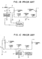
- Figs. 1A to 1C show an electric power cable line, to which the conventional methods for detecting partial discharge in an insulation of a power cable, comprising power cables 1 which are connected to each other by a normal joint 2, and each of which is connected to a high voltage conductor 4 by a terminal joint 3.
- Metal sheaths (not shown) of the power cables 1 are connected at the normal joint 2 and the terminal joint 3 to the ground by lead wires 5 and 6, respectively.
- a detecting impedance 9 is inserted between the metal sheath and the ground by use of the lead wire 6 connected to the terminal joint 3, and an apparatus 10 for detecting partial discharge is connected to both terminals of the detecting impedance 9.
- a coupling capacitor 9 is connected between the high voltage conductor 4 and the ground, thereby providing a closed circuit for the partial discharge detection.
- a coupling capacitor 8 is provided be connected at one electrode to the high voltage conductor 4 and at the other electrode to the detecting impedance 9, and a choke coil 7 is provided to stop a high frequency pulse to be passed therethrough and allow the high frequency pulse to be passed through the coupling capacitor 8.
- the partial discharge detecting apparatus 10 is connected to the both terminals of the detecting impedance.
- the detecting impedance 9 is inserted between the metal sheath and the ground by use of the lead wire 5 connected to the normal joint 2, and is connected at the both terminals to the partial discharge detecting apparatus 10.
- a predetermined high voltage is applied to the high voltage conductor 4.
- a high frequency pulse is induced between the electric conductor and the metal sheath, so that an electric potential difference is generated across the both terminals of the detecting impedance 9 in accordance with the flowing of a high frequency current through the detecting impedance 9 from the metal sheath to the ground.
- the electric potential difference is detected by the apparatus 10, so that the deterioration of the insulation is diagnosed in the apparatus 10.
- a calibration signal generator 11 is connected to the high voltage conductor 4 and the metal sheath of the terminal joint 3, and a coupling capacitor 8 of a capacitance C K is connected between the high voltage conductor 4 and the ground.
- Fig. 2B shows an equivalent circuit corresponding to the construction of Fig. 2A.
- the calibration signal generator 11 supplies a high frequency pulse having a voltage V Q through a capacitor of a capacitance C Q across the conductor 12 and the metal sheath 14 of the power cable 1, between which a capacitor 13 of a capacitance C C is formed.
- the high frequency pulse flowing through the capacitor 13 is partially shunted into the detecting impedance 9, so that an electric potential difference is generated across both terminals of the detecting impedance 9.
- the sensitivity calibration of the partial discharge detecting apparatus 10 is carried out.
- a length of a power cable line is, for instance, several Km, so that the capacitance C C is much greater than the capacitance C Q (C C > C Q ). Consequently, the voltage V 1 becomes very small, so that the calibration of the partial discharge detecting apparatus 10 is difficult in operation to be carried out.
- the high frequency pulse V Q is attenuated to reach the normal joint 2, at which the partial discharge detecting apparatus 10 is located to be connected across the detecting impedance 9.
- a length of the power cables 1 is 10 Km
- the partial discharge detecting apparatus 10 is of a frequency-sweep type signal intensity detector.
- Figs. 3A to 3C show a frequency spectrum of noise which is received by the apparatus 10, where no voltage is applied to the conductors of the power cables 1.
- Fig. 3A shows the frequency spectrum ranging up to 10 MHz which is characterized by having a high level of noise in the vicinity of 4 MHz
- Figs. 3B and 3C show enlarged frequency spectrums which cover ranges of 3 to 5 MHz and 3.8 to 4.2 MHz, respectively.
- noise is high in its level at 3.82 MHz, and 3.92 to 3.95 MHz, and low at 3.88 MHz, and 4.0 to 4.14 MHz. It should be noted that the noise level is lower at 3.88 MHz than at 3.82 MHz by approximately 35 dB.
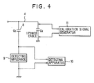
- Fig. 4 shows a simplified circuit for carrying out a method for detecting partial discharge in an insulation of an electric power cable in a first preferred embodiment according to the invention, which comprises a calibrating signal generator 11 for supplying a pulse to a power cable 1 having a capacitance Cx connected to a high voltage conductor 4, and a detecting impedance 9, connected at one terminal through a coupling capacitor 8 to the high voltage conductor 4 and at the other terminal to the ground, to which a partial discharge detecting apparatus 10 for detecting a high frequency pulse at a predetermined frequency in a predetermined frequency range is connected.
- the power cable 1 is a cross-linked polyethylene insulated cable of a rated voltage 66 KV, to which a high voltage is applied through the high voltage conductor 4.
- a calibration pulse of 100 pC (pico-coulomb) is supplied between a conductor of the power cable 1 and a metal sheath thereof from the calibration signal generator 11, so that the calibration pulse is detected through the detecting impedance 9 by the partial discharge detecting apparatus 10, in which a frequency spectrum of the detected calibration pulse is obtained as shown in Fig. 5B.
- the calibration pulse which is supplied from the calibration signal generator 11 to the power cable 1 does not contribute to the increase of a signal intensity resulted from the external noise in a frequency range less than approximately 3.5 MHz, and the signal intensity is kept to be approximately -50 dB in the frequency range more than that frequency by the calibration pulse, while the signal intensity of the external noise is decreased to be less than -60 dB in that frequency range except for the vicinity of 4MHz, especially remarkably decreased in the frequency range from 4.5 MHz to 5.5 MHz, and to be less than -70 dB in the frequency range more than 5.5 MHz.
- a S/N ratio becomes high in the frequency range from 4.8 MHz to 10 MHz.
- the noise level is remarkably low at the frequencies of 5.5 MHz, 6.2 MHz and 9.2 MHz, so that a high S/N ratio is obtained at these frequencies.
- a detecting frequency of 5.5 MHz is selected, a S/N ratio of 34 dB is obtained, because levels of the external noise and the calibration pulse are -82 dB and -48 dB, respectively.
- a detecting limitation is one fiftieth of 100 pC which is 2 pC.
- a low frequency detecting method is carried out by using a detecting impedance, a bandpass filter, and an amplifier, wherein an amplified frequency is continuously varied in the range of 10 KHz to 150 KHz, and of 10 KHz to 1000 KHz, thereby detecting a S/N ratio.
- a detecting limitation is approximately 70 pC. This means that a high sensitivity is not obtained in the low frequency detecting method.
- a tuning type partial discharge detecting apparatus which is manufactured and sold by the Nippon Keisokuki Manufacturing, Inc. of Japan is adopted to detect partial discharge by using a tuning frequency of 400 KHz.
- a S/N ratio of 10 dB, and a detecting limitation of 30 pC is obtained.
- the sensitivity is one fifteenth of that obtained in the method of Fig. 19, in which a frequency of 5.5 MHz is selected.
- Fig. 6 shows a method for detecting partial discharge in an insulation of an electric apparatus in a second preferred embodiment according to the invention, wherein like parts are indicated by like reference numerals as used in Fig. 4, except that a calibration signal generator 11 is connected to metal foil electrodes 120 provided on the insulating joint 20.
- Figs. 7A to 7C show modifications of the method for detecting partial discharge in an insulation of an electric apparatus in the second preferred embodiment.
- the calibration signal generator 11 is connected to an insulating joint 20, and a detecting apparatus including the detecting impedance 9 and the partial discharge detecting apparatus 10 is connected to another insulating joint communicated to the former insulating joint 20 by the power cable 1.
- the calibration signal generator 11 is connected to an insulating joint 20, and the detecting impedance 9, etc. are connected to a normal joint 2.
- the calibration signal generator 11 is connected to an insulating joint 20 of a power cable 1A, and the detecting impedance 9 is connected between non-ground type normal joints 2 of the power cable 1A and a power cable 1B of a different phase.
- Fig. 8 shows a method for detecting partial discharge in an insulation of an electric apparatus in a third preferred embodiment according to the invention, which comprises a 66 KV wire shielded cable 1 having a length of 10 m, a detecting coil 150 having 20 turns provided around the cable 1, a detecting impedance 9 connected to terminals of the detecting coil 150, and a partial discharge detecting apparatus 10 connected to the detecting impedance 9.
- Fig. 9 shows the wire shielded cable 1 which has a cross-sectional area of 100 mm 2 and comprises an electric conductor 151 of copper or aluminum wires, an inner semi-conductive layer 152 of, for instance, cross-linked polyethylene pregnant with conductive carbon surrounding the conductor 151, an insulation 153 of, for instance, cross-linked polyethylene provided around the inner semi-conductive layer 152, an outer semi-conductive layer 154 provided around the insulation 153, a wire shielding layer 155 of spiralled copper wires, and an anti-corrosion layer 156 of, for instance, poly-vinyl chloride.
- Fig. 10 shows a whole circuitry structure in the third preferred embodiment, wherein like parts are indicated by like reference numerals as used before.
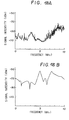
- a predetermined line voltage is applied to the wire shielded cable 1, and a frequency spectrum of external noise is obtained as shown in Fig. 11A by use of the detecting coil 150, the detecting impedance 9, and the detecting apparatus.
- a calibration pulse of 20 pC is supplied to the high voltage conductor 4 by the calibration signal generator 11, and a frequency spectrum of the calibration pulse including the external noise propagated through the wire shielded cable 1 is also obtained as shown in Fig. 11B by use of the detecting coil 150, the detecting impedance 9, and the detecting apparatus 10.
- the highest sensitivity is obtained at a frequency of approximately 11 MHz, and the effect of supplying the calibration pulse is not observed in the frequency range less than approximately 7 MHz.
- a noise level is -75 dB
- a calibration pulse level including the noise level is -55 dB, so that a S/N ratio of 20 dB is obtained in the state that a detecting limitation is approximately 3 pC.
- the noise and calibration pulse levels are both approximately -80 dB, so that a S/N ratio becomes 0 dB, thereby making it impossible to detect the calibration pulse.
- the noise is mainly caused by electro-magnetic wave in the air, noise current flowing through the shielding wire layer 155, and the floating of the ground potential due to noise current flowing through the ground. Furthermore, the reason why the detecting sensitivity is decreased at lower than a frequency of 7 MHz is that a voltage induced on the detecting coil 150 is proportional to a frequency, and the magnetic coupling between the detecting coil 150 and the wire shielded cable 1 is not dense to result in mismatching with an impedance of the cable 1 at a low frequency, and the reason why the detecting sensitivity is decreased at more than a frequency of 14 MHz is that the calibration pulse is attenuated by itself and impedance matching is not good between the detecting coil 150 and the cable 1.
- a wire shielded cable 1 as shown in Fig. 12 is used in place of the wire shielded cable 1 as shown in Fig. 9, wherein like parts are indicated by like references in the both cables 1, except that a stainless steel sheath 157 is provided between the wire shielding layer 155 and the anti-corrosion layer 156 in Fig. 12.
- the detecting coil 150 having 5 turns is provided around the cable 1 having a length of 5 m which is in the state of short-circuit at a remote end thereof.
- a calibration pulse of 2,500 pC having a rise time of 30 ns is supplied between the conductor 151 and the stainless steel sheath 157 at a near end of the cable 1, and the calibration pulse is detected by use of the detecting coil 150, the detecting impedance 9, and the detecting apparatus 10.
- the detected result is shown in Fig. 13A, from which it is understood that the calibration pulse is detected to be -13 dB at a frequency of 20 MHz, and -31 dB at a frequency of 100 MHz. Furthermore, the calibration pulse is detected to be less than a noise level of an amplifier in the detecting apparatus 10 at a frequency of more than 120 MHz.
- the stainless steel sheath 157 is removed in an axial direction of the cable 1 by 100 mm, and the detecting coil 150 is provided in the center of the stainless steel sheath removed portion by 5 turns.
- the calibration pulse which is the same as in the aforementioned modified third preferred embodiment, is supplied to the cable 1.
- the detected result is shown in Fig. 13B, in which the calibration pulse is detected to be -11 dB at a frequency of 20 MHz, and -22 dB at a frequency of 10 MHz. In the frequency rang of more than 170 MHz, a detected signal level is less than a noise level of the amplifier of the detecting apparatus 10.
- the decrease of the detected signal is approximately 2 dB at a frequency of 20 MHz, and 9 dB at a frequency of 100 MHz in accordance with a provision of the stainless steel sheath 157.
- Fig. 14 shows a method for detecting partial discharge in an insulation of an electric apparatus in a fourth preferred embodiment according to the invention.
- the detecting coil 150 is covered by a magnetic core 201 and an aluminum shielding box 202, such that the detecting coil 150 is connected through a coaxial cable 203, which is passed through a wall of the box 202, to the detecting apparatus 10.
- the detecting coil 150 is protected from picking external noise up.
- Fig. 15 shows a method for detecting partial discharge in an insulation of an electric apparatus in a fifth preferred embodiment according to the invention, wherein the detecting coil 150 is provided around the wire shielded cable 1 in the vicinity of the normal joint 2, and the detecting impedance 9 is connected to the detecting coil 150, thereby supplying a partial discharge signal to the detecting apparatus 10.
- partial discharge occurring in the normal joint 2 is detected with a high sensitivity, because the partial discharge signal is not attenuated substantially.
- Figs. 16A and 16B show two detecting coils 150 each wound on a semi-circular magnetic core 210, and positioned around the wire shielded cable 1 to face each other, such that the two detecting coils 150 are connected in series to provide a single detecting coil.
- Fig. 17 shows a method for detecting partial discharge in an insulation of an electric apparatus in a sixth preferred embodiment according to the invention, wherein like parts are indicated by like reference numerals as used before, except that the pulse injecting coil 150 is used to be connected to the pulse generator 130, and the detecting impedance 9 is connected between the stainless steel sheath 157 of the wire shielded cable i and the ground.
- a S/N ratio of 57 dB is obtained at a frequency of 5 MHz in accordance with a noise level of approximately -110 dB and a calibration pulse level of approximately -53 dB
- a S/N ratio of 23 dB is obtained at a frequency of 6.4 MHz in accordance with a noise level of approximately -53 dB and a calibration signal level of approximately -83 dB.
- the pulse injecting coil 150 is positioned at a place such as a normal joint 2, in which partial discharge tends to occur.
Landscapes
- Physics & Mathematics (AREA)
- General Physics & Mathematics (AREA)
- Testing Relating To Insulation (AREA)
Claims (3)
- Verfahren zum Bestimmen einer Frequenz, um teilweise Entladung in einer Isolation einer elektrischen Vorrichtung zu erfassen, das dasumfaßt.Bereitstellen einer oder mehrerer Elektroden auf der elektrischen Vorrichtung (1) zum Erfassen der teilweisen Entladung;Erfassen eines Frequenzspektrums des Rauschens, das von der einen oder den mehreren Elektroden erhalten wird;Erfassen eines Frequenzspektrums eines Ausgangssignals, das von der einen oder den mehreren Elektroden erhalten wird, wenn ein Kalibrierpuls auf die elektrische Vorrichtung (1) gegeben wird;Vergleichen des Frequenzspektrums des Rauschens und des Ausgangssignals, um die Frequenz zu liefern, an der ein vorbestimmtes Signal-Rausch-Verhältnis erhalten wird; undErfassen der teilweisen Entladung der Isolation der elektrischen Vorrichtung (1) bei der Frequenz
- Verfahren nach Anspruch 1, dadurch gekennzeichnet, daß die elektrische Vorrichtung ein elektrisches Leistungskabel (1) ist und der Kalibrierpuls zwischen einem Leiter (151) und eine metallische Abschirmung (157) des elektrischen Leistungskabels gegeben wird.
- Verfahren nach Anspruch 2, dadurch gekennzeichnet, daß der Kalibrierpuls auf das elektrische Leistungskabel (1) an einer geeigneten Position gegeben wird, ausgewählt aus einer Endverbindung (3), einer Isolierverbindung, einer normalen Verbindung und einem in Längsrichtung ausgewählten Abschnitt des elektrischen Leistungskabels (1).
Applications Claiming Priority (13)
| Application Number | Priority Date | Filing Date | Title |
|---|---|---|---|
| JP27792889 | 1989-10-25 | ||
| JP277928/89 | 1989-10-25 | ||
| JP1277928A JPH068845B2 (ja) | 1989-10-25 | 1989-10-25 | 部分放電測定方法 |
| JP309744/89 | 1989-11-29 | ||
| JP30974489 | 1989-11-29 | ||
| JP30974389 | 1989-11-29 | ||
| JP1309743A JPH068846B2 (ja) | 1989-11-29 | 1989-11-29 | 部分放電測定方法 |
| JP30974489A JPH068847B2 (ja) | 1989-11-29 | 1989-11-29 | ワイヤシールドケーブルの部分放電測定方法 |
| JP309743/89 | 1989-11-29 | ||
| JP1314006A JPH0833429B2 (ja) | 1989-12-02 | 1989-12-02 | 長尺電力ケーブル線路の部分放電位置標定方法 |
| JP31400689 | 1989-12-02 | ||
| JP314006/89 | 1989-12-02 | ||
| EP90101895A EP0424598B1 (de) | 1989-10-25 | 1990-01-31 | Verfahren zur Feststellung von Teilentladungen in der Isolation eines elektrischen Starkstromkabels |
Related Parent Applications (2)
| Application Number | Title | Priority Date | Filing Date |
|---|---|---|---|
| EP90101895A Division EP0424598B1 (de) | 1989-10-25 | 1990-01-31 | Verfahren zur Feststellung von Teilentladungen in der Isolation eines elektrischen Starkstromkabels |
| EP90101895.2 Division | 1990-01-31 |
Publications (2)
| Publication Number | Publication Date |
|---|---|
| EP0636890A1 EP0636890A1 (de) | 1995-02-01 |
| EP0636890B1 true EP0636890B1 (de) | 1999-08-25 |
Family
ID=27479148
Family Applications (7)
| Application Number | Title | Priority Date | Filing Date |
|---|---|---|---|
| EP03000561A Withdrawn EP1310803A3 (de) | 1989-10-25 | 1990-01-31 | Verfahren zur Detektion von Teilentladungen |
| EP94111230A Expired - Lifetime EP0629866B1 (de) | 1989-10-25 | 1990-01-31 | Verfahren zum Lokalisieren von Fehlern in elektrischen Leistungskabeln |
| EP94111232A Expired - Lifetime EP0628829B1 (de) | 1989-10-25 | 1990-01-31 | Nutzung eines Magnetkerns für das Messen von Teilentladungen |
| EP90101895A Expired - Lifetime EP0424598B1 (de) | 1989-10-25 | 1990-01-31 | Verfahren zur Feststellung von Teilentladungen in der Isolation eines elektrischen Starkstromkabels |
| EP97111457A Expired - Lifetime EP0806676B1 (de) | 1989-10-25 | 1990-01-31 | Verfahren zur Messung von Teilentladungen in einem Draht mit einer Detektionselektrode |
| EP94111231A Expired - Lifetime EP0636890B1 (de) | 1989-10-25 | 1990-01-31 | Verfahren zum Vergleich von Frequenzspektren |
| EP97111472A Withdrawn EP0806677A1 (de) | 1989-10-25 | 1990-01-31 | Verfahren zur Detektion von Teilentladungen |
Family Applications Before (5)
| Application Number | Title | Priority Date | Filing Date |
|---|---|---|---|
| EP03000561A Withdrawn EP1310803A3 (de) | 1989-10-25 | 1990-01-31 | Verfahren zur Detektion von Teilentladungen |
| EP94111230A Expired - Lifetime EP0629866B1 (de) | 1989-10-25 | 1990-01-31 | Verfahren zum Lokalisieren von Fehlern in elektrischen Leistungskabeln |
| EP94111232A Expired - Lifetime EP0628829B1 (de) | 1989-10-25 | 1990-01-31 | Nutzung eines Magnetkerns für das Messen von Teilentladungen |
| EP90101895A Expired - Lifetime EP0424598B1 (de) | 1989-10-25 | 1990-01-31 | Verfahren zur Feststellung von Teilentladungen in der Isolation eines elektrischen Starkstromkabels |
| EP97111457A Expired - Lifetime EP0806676B1 (de) | 1989-10-25 | 1990-01-31 | Verfahren zur Messung von Teilentladungen in einem Draht mit einer Detektionselektrode |
Family Applications After (1)
| Application Number | Title | Priority Date | Filing Date |
|---|---|---|---|
| EP97111472A Withdrawn EP0806677A1 (de) | 1989-10-25 | 1990-01-31 | Verfahren zur Detektion von Teilentladungen |
Country Status (5)
| Country | Link |
|---|---|
| US (2) | US5323117A (de) |
| EP (7) | EP1310803A3 (de) |
| CA (1) | CA2008898C (de) |
| DE (5) | DE69033263T2 (de) |
| NO (2) | NO302494B1 (de) |
Families Citing this family (52)
| Publication number | Priority date | Publication date | Assignee | Title |
|---|---|---|---|---|
| NO302494B1 (no) * | 1989-10-25 | 1998-03-09 | Hitachi Cable | Fremgangsmåte for deteksjon av en partiell utladning i en isolasjon av en elektrisk kraftkabel |
| NL9201944A (nl) * | 1992-11-05 | 1994-06-01 | Kema Nv | Werkwijze voor het meten van partiële ontladingen in kabels. |
| JP2952737B2 (ja) * | 1993-03-24 | 1999-09-27 | 日新電機株式会社 | 電力機器の部分放電検出装置 |
| US5574378A (en) * | 1994-12-15 | 1996-11-12 | Square D Company | Insulation monitoring system for insulated high voltage apparatus |
| EP0740159A1 (de) * | 1995-04-21 | 1996-10-30 | N.V. Kema | Messanordnung für Teilentladungen |
| US5652521A (en) * | 1995-12-19 | 1997-07-29 | Square D Company | Insulation monitoring system for insulated high voltage apparatus |
| US6313640B1 (en) * | 1998-02-03 | 2001-11-06 | Abb Power T & D Company, Inc. | System and method for diagnosing and measuring partial discharge |
| DE19832387A1 (de) * | 1998-07-18 | 2000-01-20 | Asea Brown Boveri | Verfahren zum Feststellen von Einbau- und/oder Kalibrierungsfehlern einer Mehrzahl von Signalauskopplungseinheiten eines oder mehrerer Teilentladungsmeßsysteme |
| AU1254400A (en) * | 1998-11-23 | 2000-06-13 | Harry E. Orton | Method for diagnosing insulation degradation in underground cable |
| GB9900820D0 (en) * | 1999-01-14 | 1999-03-03 | Bicc Plc | Testing cables and their joints |
| US6172862B1 (en) | 1999-06-11 | 2001-01-09 | Anthony J. Jonnatti | Partial discharge relay and monitoring device |
| US6265880B1 (en) * | 1999-06-15 | 2001-07-24 | The United States Of America As Represented By The Secretary Of The Air Force | Apparatus and method for detecting conduit chafing |
| JP2001194410A (ja) * | 1999-07-21 | 2001-07-19 | Sumitomo Electric Ind Ltd | 直埋電力ケーブルの部分放電測定方法 |
| GB0001923D0 (en) * | 2000-01-27 | 2000-03-22 | Bicc Gen Uk Cables Ltd | Partial discharge detection test link,partial discharge detection system and methods for detecting partial discharge on a power cable |
| US6882158B2 (en) * | 2001-01-24 | 2005-04-19 | General Dynamics Ots (Aerospace) Inc. | Series arc fault diagnostic for aircraft wiring |
| US6930610B2 (en) * | 2002-05-03 | 2005-08-16 | General Electric Company | Monitoring system and method for wiring systems |
| DE10246557A1 (de) * | 2002-10-05 | 2004-04-15 | Alstom | Verbindungsmuffe für eine Sammelschienenkupplung in einer gasisolierten Schaltanlage |
| AU2003267842A1 (en) * | 2002-10-10 | 2004-05-04 | Hanyang Hak Won Co., Ltd. | Hybrid type sensor for detecting high frequency partial discharge |
| GB2422967B (en) * | 2003-10-22 | 2007-06-06 | Fujikura Ltd | Insulation degradation diagnostic device |
| TWI280383B (en) * | 2004-06-29 | 2007-05-01 | Japan Ae Power Systems Corp | Partial discharge detecting sensor, and detecting device, and gas insulated electric apparatus provided with a partial discharge detecting sensor |
| US7532012B2 (en) * | 2006-07-07 | 2009-05-12 | Ambient Corporation | Detection and monitoring of partial discharge of a power line |
| US7579843B2 (en) * | 2006-10-13 | 2009-08-25 | General Electric Company | Methods and apparatus for analyzing partial discharge in electrical machinery |
| EP2107384A1 (de) * | 2008-03-31 | 2009-10-07 | ABB Research Ltd. | Bestimmung der degradierten Isolierfähigkeit und induktives Betriebselement |
| JP4949314B2 (ja) * | 2008-04-18 | 2012-06-06 | 株式会社ジェイ・パワーシステムズ | 部分放電測定方法 |
| US8098072B2 (en) * | 2008-09-24 | 2012-01-17 | Siemens Energy, Inc. | Partial discharge coupler for application on high voltage generator bus works |
| JP5238596B2 (ja) * | 2009-04-27 | 2013-07-17 | 株式会社日本自動車部品総合研究所 | 回転電機の放電量測定装置および放電量測定方法 |
| DE102009043339B4 (de) | 2009-05-26 | 2013-06-13 | Nkt Cables Gmbh | Prüfverfahren und Anordnung zur Messung von Teilentladungen an einem Einleiterseekabelspleiß |
| IT1394479B1 (it) * | 2009-05-29 | 2012-07-05 | Techimp Technologies S A Ora Techimp Technologies S R L | Strumento e procedimento di rilevazione di scariche elettriche parziali in un apparato elettrico. |
| JP5433392B2 (ja) * | 2009-12-16 | 2014-03-05 | 日立オートモティブシステムズ株式会社 | 電動車両用回転電機、駆動制御装置および絶縁診断方法 |
| EP2360486B1 (de) * | 2010-02-24 | 2018-09-05 | Omicron electronics GmbH | Verfahren zur Kalibrierung einer Teilentladungsmesseinrichtung |
| IT1398250B1 (it) * | 2010-03-10 | 2013-02-22 | Techimp Technologies S A Ora Techimp Technologies S R L | Strumento e procedimento per rilevare scariche elettriche parziali |
| EP2395364A1 (de) * | 2010-06-14 | 2011-12-14 | Alstom Technology Ltd | Verfahren zur Detektion der in einem elektrischen System erzeugten Teilentladung und elektrisches System mit einer Vorrichtung zur Detektion der darin erzeugten Teilentladungen |
| WO2012003426A2 (en) * | 2010-07-02 | 2012-01-05 | Reynolds Brett S | Apparatus for calibrated non-invasive measurement of electrical current |
| NL2005431C2 (en) * | 2010-10-01 | 2012-04-03 | Locamation B V | Method and system for on-line measurement in power cables. |
| CA2815403C (en) * | 2010-11-04 | 2016-06-21 | Alstom Technology Ltd | Partial discharge sensor for a high voltage insulation monitoring device |
| EP2887074B1 (de) * | 2013-12-18 | 2020-11-25 | 3M Innovative Properties Company | Spannungssensor |
| US10398465B2 (en) * | 2014-04-29 | 2019-09-03 | Misonix Incorporated | Ultrasonic surgical instrument assembly, related accessory, and associated surgical method |
| FR3021410B1 (fr) * | 2014-05-20 | 2016-05-13 | Nexans | Appareillage sec a haute tension equipe d’un dispositif de controle en continu |
| GB2531325A (en) * | 2014-10-16 | 2016-04-20 | Repl Internat Ltd | Medium-Voltage cable joint |
| CN104483546B (zh) * | 2014-12-09 | 2017-02-22 | 南京国睿安泰信科技股份有限公司 | 一种fpga数字逻辑信号的频谱分析方法 |
| US11177055B2 (en) | 2017-03-06 | 2021-11-16 | Savannah River Nuclear Solutions, Llc | Leading/lagging cable referencing platform for monitoring the health of underground cable networks |
| RU2639578C1 (ru) * | 2017-04-20 | 2017-12-21 | Илья Николаевич Джус | Способ измерения частичных разрядов |
| RU2651641C1 (ru) * | 2017-04-27 | 2018-04-23 | Федеральное государственное бюджетное образовательное учреждение высшего образования "Кубанский государственный аграрный университет имени И.Т. Трубилина" | Способ оценки качества кабеля |
| DE102017116613B3 (de) * | 2017-07-24 | 2018-08-09 | Maschinenfabrik Reinhausen Gmbh | Verfahren und Prüfvorrichtung zur Messung von Teilentladungsimpulsen eines geschirmten Kabels |
| US11670930B2 (en) * | 2018-09-10 | 2023-06-06 | 3M Innovative Properties Company | Support structure for cable and cable accessory condition monitoring devices |
| WO2020055667A2 (en) | 2018-09-10 | 2020-03-19 | 3M Innovative Properties Company | Electrical power cable monitoring device including partial discharge sensor |
| WO2020055666A1 (en) | 2018-09-10 | 2020-03-19 | 3M Innovative Properties Company | Electrical power cable monitoring device using low side electrode and earth ground separation |
| CN109752634B (zh) * | 2019-03-01 | 2024-02-27 | 浙江新图维电子科技有限公司 | 一种电缆接头谐振式互感局放检测装置及检测方法 |
| CN113311291A (zh) * | 2021-05-28 | 2021-08-27 | 国网江苏省电力有限公司无锡供电分公司 | 大段长高压电缆的局部放电检测灵敏度测试装置及方法 |
| CN113884819A (zh) * | 2021-11-01 | 2022-01-04 | 西南交通大学 | 一种牵引供电系统电缆接头故障定位系统及方法 |
| CN114002553A (zh) * | 2021-11-01 | 2022-02-01 | 西南交通大学 | 一种牵引供电27.5kV电缆接头故障识别方法 |
| CN114114123A (zh) * | 2021-11-29 | 2022-03-01 | 广东电网有限责任公司广州供电局 | 局部放电检测传感器的校验装置及方法 |
Family Cites Families (37)
| Publication number | Priority date | Publication date | Assignee | Title |
|---|---|---|---|---|
| US2832042A (en) * | 1954-04-30 | 1958-04-22 | Northern Electric Co | Fault locating apparatus |
| US2792568A (en) * | 1955-03-04 | 1957-05-14 | Specialties Dev Corp | Network for detecting the failure of the insulation of electrically conductive cables |
| US3252085A (en) * | 1963-09-12 | 1966-05-17 | Western Electric Co | Method of locating coaxial cable arcing faults utilizing a magnetic blowout principle |
| US3346808A (en) * | 1963-09-25 | 1967-10-10 | Gen Cable Corp | Apparatus including capacitance means for measuring ionization in high voltage cables under conditions of heavy external interference |
| US3370227A (en) * | 1966-09-20 | 1968-02-20 | Gen Cable Corp | Apparatus to measure continuously corona inception and extinction voltages in movinginsulated cable cores |
| US3430137A (en) * | 1967-07-10 | 1969-02-25 | Gen Cable Corp | Method and apparatus for automatic measurements of corona inception and extinction voltages |
| JPS4970183A (de) * | 1972-11-10 | 1974-07-06 | ||
| US4064454A (en) * | 1973-02-14 | 1977-12-20 | Matsushita Electric Industrial Co., Ltd. | Corona discharge detecting device |
| US4001674A (en) * | 1975-07-29 | 1977-01-04 | General Electric Company | Method of testing the voltage withstand ability of a high voltage d-c cable at a voltage higher than its normal operating voltage while carrying current |
| DE2605418C2 (de) * | 1976-02-12 | 1982-05-19 | Schaltbau Gesellschaft mbH, 8000 München | Anordnung zur Prüfung der elektrischen Festigkeit von isolierten elektrischen Leitern |
| US4134061A (en) * | 1977-02-02 | 1979-01-09 | Gudgel Howard S | Pipe current detector with plural magnetic flux detectors |
| GB2037060B (en) * | 1978-10-02 | 1982-10-27 | Texas Instruments Inc | Electric power cables |
| JPS56157873A (en) * | 1980-05-09 | 1981-12-05 | Hitachi Ltd | Partial discharge monitor device for dry type transformer |
| JPS57189074A (en) * | 1981-05-18 | 1982-11-20 | Showa Electric Wire & Cable Co Ltd | Corona measuring method for power cable |
| DE3148735A1 (de) * | 1981-12-09 | 1986-10-09 | Fried. Krupp Gmbh, 4300 Essen | Verfahren und vorrichtung zur frequenzanalyse |
| JPS58106473A (ja) * | 1981-12-19 | 1983-06-24 | Sumitomo Electric Ind Ltd | ケ−ブルの銅テ−プ断線発見方法 |
| US4446420A (en) * | 1982-01-28 | 1984-05-01 | Hydro Quebec | Method and device for detecting and locating fault and/or partial discharges in a gas-insulated electrical equipment |
| JPS5991376A (ja) * | 1982-11-16 | 1984-05-26 | Kansai Electric Power Co Inc:The | 電力ケ−ブルの絶縁劣化診断方法 |
| DE3347275A1 (de) * | 1983-12-28 | 1985-07-11 | Messwandler-Bau Gmbh, 8600 Bamberg | Messverfahren zur feststellung von teilentladungen und vorrichtung zur durchfuehrung dieses verfahrens |
| DE3569988D1 (en) * | 1984-09-28 | 1989-06-08 | Fuji Electric Co Ltd | Partial discharge measuring device |
| GB8425761D0 (en) * | 1984-10-11 | 1984-11-14 | Raychem Sa Nv | Remote measurement of conditions |
| JPS61108976A (ja) * | 1984-11-01 | 1986-05-27 | Mitsubishi Electric Corp | ガス絶縁母線の故障位置検出装置 |
| JPS6211177A (ja) * | 1985-07-09 | 1987-01-20 | Hitachi Cable Ltd | ケ−ブルの部分放電測定方法 |
| DE3610170A1 (de) * | 1986-03-26 | 1987-10-01 | Bosch Gmbh Robert | Verfahren zum eichen einer messschaltung |
| DE3764009D1 (de) * | 1986-04-14 | 1990-09-06 | Siemens Ag | Verfahren und vorrichtungen zur erkennung und lokalisierung von schaeden in elektrischen anlagen. |
| US4789829A (en) * | 1986-07-18 | 1988-12-06 | Science Application International Corporation | Method and apparatus for determining RE gasket shielding effectiveness |
| FI863487A (fi) * | 1986-08-27 | 1988-02-28 | Matti Viikari | Pao elektromagnetisk induktion baserande foerfarande och anordning foer kontroll av skicktet av elektrisk isolering hos ledningar i ett ledande medium. |
| US4929903A (en) * | 1987-08-07 | 1990-05-29 | Mitsui Petrochemical Industries, Ltd. | Method of and apparatus for assessing insulation conditions |
| JP2831355B2 (ja) * | 1988-02-29 | 1998-12-02 | 三井化学株式会社 | 絶縁状態の検知方法 |
| JP2869067B2 (ja) * | 1988-02-26 | 1999-03-10 | 三井化学株式会社 | 絶縁状態の検知装置 |
| DE3802841A1 (de) * | 1988-02-01 | 1989-08-03 | Standard Elektrik Lorenz Ag | Verfahren zur charakterisierung optischer eigenschaften von halbleiter-lasern und vorrichtung zur durchfuehrung des verfahrens |
| US4887041A (en) * | 1988-02-17 | 1989-12-12 | University Of Connecticut | Method and instrumentation for the detection, location and characterization of partial discharges and faults in electric power cables |
| US4876721A (en) * | 1988-03-03 | 1989-10-24 | Martin Marietta Energy Systems, Inc. | Method and device for identifying different species of honeybees |
| US4853616A (en) * | 1988-07-21 | 1989-08-01 | Atlantic Richfield Company | Detection of water saturation in insulation at cased road crossings |
| US4935176A (en) * | 1988-12-09 | 1990-06-19 | Southwire Company | Method of and apparatus for detecting defects in an electrical conductor |
| US4967158A (en) * | 1989-03-31 | 1990-10-30 | Hydro-Quebec | Portable detector device for detecting partial electrical discharge in live voltage distribution cables and/or equipment |
| NO302494B1 (no) * | 1989-10-25 | 1998-03-09 | Hitachi Cable | Fremgangsmåte for deteksjon av en partiell utladning i en isolasjon av en elektrisk kraftkabel |
-
1990
- 1990-01-30 NO NO900431A patent/NO302494B1/no not_active IP Right Cessation
- 1990-01-30 CA CA002008898A patent/CA2008898C/en not_active Expired - Fee Related
- 1990-01-31 DE DE69033263T patent/DE69033263T2/de not_active Expired - Fee Related
- 1990-01-31 DE DE69033279T patent/DE69033279T2/de not_active Expired - Fee Related
- 1990-01-31 DE DE69026186T patent/DE69026186T2/de not_active Expired - Fee Related
- 1990-01-31 EP EP03000561A patent/EP1310803A3/de not_active Withdrawn
- 1990-01-31 EP EP94111230A patent/EP0629866B1/de not_active Expired - Lifetime
- 1990-01-31 EP EP94111232A patent/EP0628829B1/de not_active Expired - Lifetime
- 1990-01-31 EP EP90101895A patent/EP0424598B1/de not_active Expired - Lifetime
- 1990-01-31 DE DE69032763T patent/DE69032763T2/de not_active Expired - Fee Related
- 1990-01-31 EP EP97111457A patent/EP0806676B1/de not_active Expired - Lifetime
- 1990-01-31 EP EP94111231A patent/EP0636890B1/de not_active Expired - Lifetime
- 1990-01-31 DE DE69032808T patent/DE69032808T2/de not_active Expired - Fee Related
- 1990-01-31 EP EP97111472A patent/EP0806677A1/de not_active Withdrawn
-
1991
- 1991-10-28 US US07/784,728 patent/US5323117A/en not_active Expired - Fee Related
-
1993
- 1993-12-08 US US08/163,572 patent/US5469067A/en not_active Expired - Fee Related
-
1997
- 1997-10-10 NO NO974684A patent/NO309881B1/no not_active IP Right Cessation
Also Published As
| Publication number | Publication date |
|---|---|
| EP0424598A3 (en) | 1992-06-24 |
| EP0424598B1 (de) | 1996-03-27 |
| NO309881B1 (no) | 2001-04-09 |
| US5469067A (en) | 1995-11-21 |
| EP0424598A2 (de) | 1991-05-02 |
| DE69026186T2 (de) | 1996-08-08 |
| NO900431D0 (no) | 1990-01-30 |
| EP0806676B1 (de) | 1999-09-01 |
| CA2008898C (en) | 1998-11-24 |
| DE69033279D1 (de) | 1999-10-07 |
| DE69033263T2 (de) | 1999-12-09 |
| DE69033279T2 (de) | 1999-12-30 |
| EP1310803A2 (de) | 2003-05-14 |
| DE69032763T2 (de) | 1999-04-01 |
| DE69033263D1 (de) | 1999-09-30 |
| EP0806677A1 (de) | 1997-11-12 |
| NO900431L (no) | 1991-04-26 |
| US5323117A (en) | 1994-06-21 |
| NO974684L (no) | 1991-04-26 |
| DE69032808T2 (de) | 1999-04-22 |
| CA2008898A1 (en) | 1991-04-25 |
| NO974684D0 (no) | 1997-10-10 |
| EP0629866A1 (de) | 1994-12-21 |
| NO302494B1 (no) | 1998-03-09 |
| EP0628829A1 (de) | 1994-12-14 |
| DE69026186D1 (de) | 1996-05-02 |
| EP1310803A3 (de) | 2003-10-22 |
| EP0806676A1 (de) | 1997-11-12 |
| EP0628829B1 (de) | 1998-11-11 |
| EP0636890A1 (de) | 1995-02-01 |
| DE69032808D1 (de) | 1999-01-14 |
| EP0629866B1 (de) | 1998-12-02 |
| DE69032763D1 (de) | 1998-12-17 |
Similar Documents
| Publication | Publication Date | Title |
|---|---|---|
| EP0636890B1 (de) | Verfahren zum Vergleich von Frequenzspektren | |
| Ahmed et al. | On-line partial discharge detection in cables | |
| EP0679261B1 (de) | Verfahren und gerät zur messung von teilentladungen in kabeln | |
| WO2000042444A1 (en) | Testing electric cables and their joints | |
| US3440528A (en) | Method and apparatus for locating voids in an insulated electrical cable | |
| Lee et al. | Characteristics of high frequency partial discharge for artificially defected extra high voltage accessories | |
| JP2978718B2 (ja) | 電力ケーブルの普通接続部 | |
| JPH02161369A (ja) | 部分放電測定方法 | |
| JPH08262097A (ja) | 部分放電測定方法 | |
| JP2000221229A (ja) | 部分放電検出装置及び部分放電検出方法 | |
| Polyakov | Research of Partial Discharge Registration Effectiveness Using HFCT Sensor | |
| JPH03170077A (ja) | ワイヤシールドケーブルの部分放電測定方法 | |
| JPH10153638A (ja) | 電力ケーブル気中終端部部分放電測定方法 | |
| JPH0519008A (ja) | 部分放電検出装置 | |
| JPH0339670A (ja) | 部分放電測定方法 | |
| JPH06273472A (ja) | 部分放電検出センサ | |
| JP2860002B2 (ja) | 高周波部分放電センサ | |
| JPH06308191A (ja) | 共振型部分放電検出装置の試験方法 | |
| JPH06331691A (ja) | 電力ケーブルおよびその接続部の部分放電測定方法 | |
| JPH10322823A (ja) | 電気機器の絶縁診断方法及び装置 | |
| JPH02222845A (ja) | 試験ケーブルの放電点検知方法 | |
| JPH05256896A (ja) | 共振型部分放電検出装置の校正方法 | |
| JPH06317626A (ja) | 共振型部分放電検出装置 | |
| JPH0634697A (ja) | 部分放電検出方法 | |
| JPH05312888A (ja) | 部分放電センサ |
Legal Events
| Date | Code | Title | Description |
|---|---|---|---|
| PUAI | Public reference made under article 153(3) epc to a published international application that has entered the european phase |
Free format text: ORIGINAL CODE: 0009012 |
|
| 17P | Request for examination filed |
Effective date: 19940719 |
|
| AC | Divisional application: reference to earlier application |
Ref document number: 424598 Country of ref document: EP |
|
| AK | Designated contracting states |
Kind code of ref document: A1 Designated state(s): DE FR GB IT SE |
|
| 17Q | First examination report despatched |
Effective date: 19980417 |
|
| GRAG | Despatch of communication of intention to grant |
Free format text: ORIGINAL CODE: EPIDOS AGRA |
|
| GRAG | Despatch of communication of intention to grant |
Free format text: ORIGINAL CODE: EPIDOS AGRA |
|
| GRAH | Despatch of communication of intention to grant a patent |
Free format text: ORIGINAL CODE: EPIDOS IGRA |
|
| GRAH | Despatch of communication of intention to grant a patent |
Free format text: ORIGINAL CODE: EPIDOS IGRA |
|
| GRAA | (expected) grant |
Free format text: ORIGINAL CODE: 0009210 |
|
| AC | Divisional application: reference to earlier application |
Ref document number: 424598 Country of ref document: EP |
|
| AK | Designated contracting states |
Kind code of ref document: B1 Designated state(s): DE FR GB IT SE |
|
| REF | Corresponds to: |
Ref document number: 69033263 Country of ref document: DE Date of ref document: 19990930 |
|
| ITF | It: translation for a ep patent filed |
Owner name: FUMERO BREVETTI S.N.C. |
|
| ET | Fr: translation filed | ||
| PLBE | No opposition filed within time limit |
Free format text: ORIGINAL CODE: 0009261 |
|
| STAA | Information on the status of an ep patent application or granted ep patent |
Free format text: STATUS: NO OPPOSITION FILED WITHIN TIME LIMIT |
|
| 26N | No opposition filed | ||
| REG | Reference to a national code |
Ref country code: GB Ref legal event code: IF02 |
|
| PGFP | Annual fee paid to national office [announced via postgrant information from national office to epo] |
Ref country code: SE Payment date: 20040107 Year of fee payment: 15 |
|
| PGFP | Annual fee paid to national office [announced via postgrant information from national office to epo] |
Ref country code: FR Payment date: 20040108 Year of fee payment: 15 |
|
| PGFP | Annual fee paid to national office [announced via postgrant information from national office to epo] |
Ref country code: GB Payment date: 20040128 Year of fee payment: 15 |
|
| PGFP | Annual fee paid to national office [announced via postgrant information from national office to epo] |
Ref country code: DE Payment date: 20040212 Year of fee payment: 15 |
|
| PG25 | Lapsed in a contracting state [announced via postgrant information from national office to epo] |
Ref country code: IT Free format text: LAPSE BECAUSE OF NON-PAYMENT OF DUE FEES;WARNING: LAPSES OF ITALIAN PATENTS WITH EFFECTIVE DATE BEFORE 2007 MAY HAVE OCCURRED AT ANY TIME BEFORE 2007. THE CORRECT EFFECTIVE DATE MAY BE DIFFERENT FROM THE ONE RECORDED. Effective date: 20050131 Ref country code: GB Free format text: LAPSE BECAUSE OF NON-PAYMENT OF DUE FEES Effective date: 20050131 |
|
| PG25 | Lapsed in a contracting state [announced via postgrant information from national office to epo] |
Ref country code: SE Free format text: LAPSE BECAUSE OF NON-PAYMENT OF DUE FEES Effective date: 20050201 |
|
| PG25 | Lapsed in a contracting state [announced via postgrant information from national office to epo] |
Ref country code: DE Free format text: LAPSE BECAUSE OF NON-PAYMENT OF DUE FEES Effective date: 20050802 |
|
| GBPC | Gb: european patent ceased through non-payment of renewal fee |
Effective date: 20050131 |
|
| PG25 | Lapsed in a contracting state [announced via postgrant information from national office to epo] |
Ref country code: FR Free format text: LAPSE BECAUSE OF NON-PAYMENT OF DUE FEES Effective date: 20050930 |
|
| EUG | Se: european patent has lapsed | ||
| REG | Reference to a national code |
Ref country code: FR Ref legal event code: ST |