EP0635767A2 - Dispositif pour le fixage - Google Patents
Dispositif pour le fixage Download PDFInfo
- Publication number
- EP0635767A2 EP0635767A2 EP94111225A EP94111225A EP0635767A2 EP 0635767 A2 EP0635767 A2 EP 0635767A2 EP 94111225 A EP94111225 A EP 94111225A EP 94111225 A EP94111225 A EP 94111225A EP 0635767 A2 EP0635767 A2 EP 0635767A2
- Authority
- EP
- European Patent Office
- Prior art keywords
- heating roll
- nip portion
- fusing device
- fusing
- heat
- Prior art date
- Legal status (The legal status is an assumption and is not a legal conclusion. Google has not performed a legal analysis and makes no representation as to the accuracy of the status listed.)
- Granted
Links
Images
Classifications
-
- G—PHYSICS
- G03—PHOTOGRAPHY; CINEMATOGRAPHY; ANALOGOUS TECHNIQUES USING WAVES OTHER THAN OPTICAL WAVES; ELECTROGRAPHY; HOLOGRAPHY
- G03G—ELECTROGRAPHY; ELECTROPHOTOGRAPHY; MAGNETOGRAPHY
- G03G15/00—Apparatus for electrographic processes using a charge pattern
- G03G15/20—Apparatus for electrographic processes using a charge pattern for fixing, e.g. by using heat
- G03G15/2003—Apparatus for electrographic processes using a charge pattern for fixing, e.g. by using heat using heat
- G03G15/2014—Apparatus for electrographic processes using a charge pattern for fixing, e.g. by using heat using heat using contact heat
- G03G15/2017—Structural details of the fixing unit in general, e.g. cooling means, heat shielding means
- G03G15/2025—Structural details of the fixing unit in general, e.g. cooling means, heat shielding means with special means for lubricating and/or cleaning the fixing unit, e.g. applying offset preventing fluid
-
- G—PHYSICS
- G03—PHOTOGRAPHY; CINEMATOGRAPHY; ANALOGOUS TECHNIQUES USING WAVES OTHER THAN OPTICAL WAVES; ELECTROGRAPHY; HOLOGRAPHY
- G03G—ELECTROGRAPHY; ELECTROPHOTOGRAPHY; MAGNETOGRAPHY
- G03G15/00—Apparatus for electrographic processes using a charge pattern
- G03G15/20—Apparatus for electrographic processes using a charge pattern for fixing, e.g. by using heat
- G03G15/2003—Apparatus for electrographic processes using a charge pattern for fixing, e.g. by using heat using heat
- G03G15/2014—Apparatus for electrographic processes using a charge pattern for fixing, e.g. by using heat using heat using contact heat
- G03G15/206—Structural details or chemical composition of the pressure elements and layers thereof
-
- G—PHYSICS
- G03—PHOTOGRAPHY; CINEMATOGRAPHY; ANALOGOUS TECHNIQUES USING WAVES OTHER THAN OPTICAL WAVES; ELECTROGRAPHY; HOLOGRAPHY
- G03G—ELECTROGRAPHY; ELECTROPHOTOGRAPHY; MAGNETOGRAPHY
- G03G2215/00—Apparatus for electrophotographic processes
- G03G2215/20—Details of the fixing device or porcess
- G03G2215/2093—Release agent handling devices
- G03G2215/2096—Release agent handling devices using porous fluoropolymers for wicking the release agent
Definitions
- the present invention relates to a fusing device for use in equipment such as copying machines, facsimiles, printers and the like making use of electrophotographic processing.
- a heat-fusing device there is a known device including a heating roll having a heater in a cylindrical core bar and a heat-resistant plastic layer formed on the outer peripheral surface of the core bar, and a pressure roll which is forced to contact the heating roll and has a heat-resistant elastic layer formed on the outer peripheral surface of a cylindrical core bar.
- the device of the aforesaid heating roll type is used for fusing by passing a recording sheet carrying an unfused toner image through the nip portion between both rolls.
- such a fusing device of the heating roll type requires the heating roll and when the heating roll is manufactured, expensive heat-resistant elastic material such as silicone rubber, fluororubber or the like is used to form the heat-resistant elastic layer.
- the problem is that equipment cost is relatively high.
- the contact (nip portion) between the heat and pressure rolls ought to be at least 4 to 10 mm wide to secure predetermined fusing conditions. Consequently, it is necessary to set the roll diameter on the large size or provide a loading mechanism for applying a heavy load, for example, and the heat and pressure rolls are hardly made compact; this naturally results in large-sized and complicated devices.
- An object of the present invention is to provide a fusing device as what is of such a type as to employ a heat-resistant solid elastic member in place of a pressure roll, so that the size and cost of the device are made reducible without spoiling excellent stable fusing performance.
- the invention provides a fusing device for fusing a toner image by passing a recording sheet carrying an unfused toner image by means of a torque of a heating roll through a nip portion between the rotating heating roll and a heat-resistant solid elastic member which is forced to contact an outer peripheral surface of the heating roll to form the nip portion,
- the heat-resistant solid elastic member including: an elastic body penetrated with a liquid release agent; and a release-agent penetration control film formed of a porous film having a region which covers a surface of the elastic body and corresponds to at least the nip portion.
- a fusing device of the invention for fusing a toner image by passing a recording sheet carrying an unfused toner image by means of the torque of a heating roll through a nip portion between the rotating heating roll and a heat-resistant solid elastic member which is forced to contact an outer peripheral surface of the heating roll to form the nip portion is characterized in that the heat-resistant solid elastic member includes an elastic body penetrated with a liquid release agent, and a release-agent penetration control film formed of a porous film having a region which covers the surface of the elastic body and corresponds to at least the nip portion.
- a support body for holding the heat-resistant solid elastic member use can be made of a sheet metal, a die-cast metal, a plastic material or the like.
- the support body itself may be either rigid body or what is elastic like a spring member.
- the heat-resistant solid elastic member cooperates with the support body in forming an elastic press member, which may have a convex profile with respect to the heating roll or a concave profile along the peripheral surface of the heating roll; in other words, it is important for the press member to form a nip portion necessary for fusing when it is forced to contact the heating roll.
- the diameter of the heating roll is desired to be made as small as possible, whereas the minimum fusing temperature (approximately 120°C to 140°C) required for the fusing of toner powder must be secured.
- the surface temperature of the heating roll set at about 130°C, for example, the necessary nip width ranges from 2 mm to 8 mm when ordinary toner images are fused at a rate of 4 cpm to 8 cpm (copy per minute).
- the diameter of the heating roll should preferably be set not greater than five times the nip width when a low power consumption heating device such as a Coltz lamp of 500 W or less is used and should preferably be set not less than 2.5 times when the heating device is held inside.
- the elastic body which forms the heat-resistant solid elastic member may be an elastic body which can be penetrated with the liquid release agent and also gives pressure necessary for fusing when the elastic member is forced to contact the heating roll.
- a porous or foamed body may be used as the elastic material and this is also the case with rubber material exemplarily shown in, for example, Japanese Utility Model Unexamined Publication No. Sho. 63-82861.
- the release-agent penetration control film forming the heat-resistant solid elastic member is intended to properly regulate the supply of the release agent with which the elastic body is penetrated to the nip portion when the nip portion is formed by joining the heat-resistant solid elastic member and the heating roll together by pressing. It is therefore only necessary for the film to be able to supply the appropriate quantity of the release agent to the nip portion.
- Such a film may be formed of an elongated porous polytetrafluoroethylene film (Goatex GT Sheet manufactured by Japan Goatex Co., Ltd.) which is 3 to 100 ⁇ m thick, with a pore diameter of 0.1 to 100 ⁇ m and a pore percentage of 30 to 95%, a film member prepared by boring extra-fine holes or slits of 50 ⁇ m to 2.0 mm in diameter in a region of a fluorofilm 5 to 500 ⁇ m thick corresponding to the nip portion, or a composite film member prepared by bonding the above film member and a porous film (including unwoven fabric, paper, etc.) together.
- a porous polytetrafluoroethylene film Goatex GT Sheet manufactured by Japan Goatex Co., Ltd.
- the means of supplying the release agent that is, silicone oil
- the release agent that is, silicone oil
- the offsetting on the heating roll turns round once and runs into the nip portion before remaining in the neighborhood of the entrance of the fusing nip portion.
- the neighborhood of the entrance of the fusing nip portion corresponds to the end at which fusing paper is caused to run in, offset toner remaining at the fusing nip portion is discharged together with the paper each time a copy is made and the offset toner is prevented from remaining on the peripheral surface of the heating roll.
- the offset toner produced on the heating roll is accumulated in the region of the supply member to form a lump of offset toner.
- the offset toner is released sometimes and causes a large offset image to be generated on the copying paper.
- the fusing device is characterized by the provision of the aforesaid heat-resistant solid elastic member in such a way that the center line of the solid elastic member in its width direction intersects the rotary shaft of the heating roll.
- the heating roll will bend because of the load applied thereto to obtain pressure necessary for fusing, thus resulting in letting the nip width decrease toward its central part from both end portions; in other words, the former is made to intersect the latter only to prevent the overall nip width from becoming uneven.
- the nip width is uniformized and this makes it possible to effect heat-fusing and to supply the release agent uniformly. Moreover, the uniform nip width is obtainable even though use is made of, for example, a small diameter heating roll which is less rigid and flexible.
- the fusing device according to the present invention is characterized in that the angle of intersection between the center line in the width direction of the heat-resistant solid elastic member and the rotary shaft of the heating roll is in the range of 0.5 to 3.0°, preferably 0.5 to 2.0°.
- the fusing device is characterized in that a release layer made of silicone rubber or fluororubber is formed on the outer peripheral surface of the heating roll and that the surface of the heat-resistant solid elastic member on the side where it contacts the heating roll is configured so as to have a radius of curvature greater than the radius of the heating roll.
- the aforesaid heating roll is equipped with a heater in a cylindrical core material and the release layer on its outer peripheral surface.
- a release layer having excellent heat resistance and toner release properties, it is preferred to use a rubber layer made of HTV (High Temperature Vulcanization) silicone rubber, RTV (Room Temperature Vulcanization) silicone rubber, fluororubber or the like.
- HTV High Temperature Vulcanization
- RTV Room Temperature Vulcanization
- the surface of the heat-resistant solid elastic member on the side where it contacts the heating roll is configured so as to have a radius of curvature greater than the radius of the heating roll, whereby not only the nip width but also a fusing rate can be increased, whereas the diameter of the heating roll becomes reducible.
- the nip width has been limited in size to 1/10 to 1/5 time the diameter of the heating roll; however, the present invention makes it substantially possible to double the value of the width thereof (1/5 to 1/2.5 time).
- a heating roll having a diameter of as small as 10 to 20 mm can be used according to the present invention.
- the release properties of the recording sheet from the heating roll improves and a small-sized low-cost, quick-start device is simultaneously attainable as the diameter of its heating roll is reducible.
- the fusing device is characterized in that a protrusion is provided on the downstream side in the direction in which the sheet is conveyed in a region corresponding to the nip portion of the heat-resistant solid elastic member or otherwise the hardness of the elastic body on the downstream side in the direction in which the sheet is conveyed in the region corresponding to the nip portion of the heat-resistant solid elastic member is set greater than that of an elastic body in any other portion.
- the load applied to the heating roll can be set as low as approximately 2/1 to 1/10 of the total load 20 to 200 kg in the conventional device, whereby pressure (0.5 to 5.0 kg/cm2) necessary for fusing is fully available.
- pressure 0.5 to 5.0 kg/cm2
- the load applied to the heating roll becomes reducible further since pressure necessary for fusing is available only in a portion where the protrusion exists or at the extra-hard elastic body.
- the configuration and hardness of the protrusion and the extra-hard elastic body are not restrictive as long as the pressure needed for fusing is obtainable.
- the fusing device is characterized in that a temperature sensor for regulating the temperature of the heating roll is provided on the upstream side in the direction in which the sheet is conveyed in the region corresponding to the nip portion of heat-resistant solid elastic member.
- the temperature sensor may be provided between the elastic body in the region of the nip portion of the heat-resistant solid elastic member and the film. Moreover, a temperature detection signal from the sensor is fed back to, for example, a heating temperature control circuit of the heating roll.
- the nip portion is formed by the heat-resistant solid elastic member in cooperation with the heating roll, and the elastic member also functions as a release agent supplier. Moreover, the uniform nip width is made obtainable by properly intersecting the heat-resistant solid elastic member and the heating roll and joining them together by pressing.
- the release agent supplier placed around the heating roll in the conventional apparatus can be dispensed with and a small-sized low cost apparatus is thus attainable. Since the proper quantity of the release agent is supplied from the nip portion having uniform width, the recording sheet is allowed to peel off the heating roll smoothly and the release mechanism disposed around the heating roll can also be dispensed with. Further, ordinary toner powder may be used by supplying the release agent at a ratio of 0.1 to 2.0 mg/copy without using wax-containing oilless toner which is normally used for small-sized copying machines very often.
- toner powder can efficiently be heated and fused to effect excellent fixation in the device according to the present invention since the unfused toner-image carrying side of the recording sheet is caused to face the heating roll at the time of fusing.
- the heating roll is provided with the special release layer and the specific configuration (e.g., curved surface) for the contact surface of the heat-resistant solid elastic member is provided so as to improve the release properties of the recording sheet from the heating roll. Therefore, the release mechanism can be dispensed with to ensure that the device is made small-sized and less costly.
- the omission of the release mechanism like this not only obviates the possibility of letting such a mechanism interfere with the work of taking out the recording sheet jammed in the fusing device but also prevents the abrasion of the surface of the heating roll due to release fingers and any accident arising when the worker happens to touch the release finger. Since only the heat-resistant solid elastic member is disposed around the heating roll, the construction of the device is considerably simplified. In addition, the heat of the heating roll is kept from being absorbed and accordingly being wasted by any other member in contact therewith as only the solid elastic member is allowed to contact the heating roll and this makes it possible to considerably shorten the time (warm-up time) required for the heating roll to rise up from the room temperature up to the temperature level at which fusing can be carried out.
- the provision of the protrusion in a predetermined region of the heat-resistant solid elastic member or the use of the extra-hard elastic body makes obtainable a pressure higher than that in any other region at the time of fusing, so that the load applied to the heating roll becomes reducible.
- the installation of the temperature sensor for controlling the temperature of the heating roll in the region corresponding to the nip portion of the heat-resistant solid elastic member makes it possible to detect the nip portion heating temperature directly to ensure that the fusing temperature is set accurately as compared with the conventional device in which such a sensor is installed around the heating roll on this side of the nip portion. Since the release agent is always present at the interface between the temperature sensor and the heating roll, the surface of the heating roll is almost free from the damage caused by the sensor.
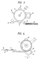
- FIG. 3 shows a schematic construction of an electrophotographic device using a fusing device of the present invention.
- Reference numeral 12 designates a photoreceptor; 13, charging means for uniformly charging the photoreceptor in a dark place; 14, latent image forming means for forming a latent image in the photoreceptor by exposing the photoreceptor to an optical image corresponding to an original image; 15, developing means for developing the latent image into a visible image with toner powder; 16, transfer means for transferring the developed image onto a transfer member; 17, a fusing device according to the present invention; 18, cleaning means; 19, a transfer paper; 30, a sheet feed roller; and 31, a rod for rotating the photoreceptor in a direction.
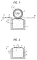
- Fig. 1 shows a fusing device according to an embodiment of the present invention, wherein reference numeral 1 designates a heating roll; 2, a heat-resistant solid elastic member forced to contact the heating roll 1; 20, a recording sheet; 21, unfused toner powder formed on the recording sheet 20; and reference symbol A, a direction in which the recording sheet is conveyed.
- reference numeral 1 designates a heating roll; 2, a heat-resistant solid elastic member forced to contact the heating roll 1; 20, a recording sheet; 21, unfused toner powder formed on the recording sheet 20; and reference symbol A, a direction in which the recording sheet is conveyed.
- the heating roll 1 is prepared by dip-coating silicone RTV rubber on the outer peripheral surface of a cylindrical iron core member 3 which is 15 mm in outer diameter, 0.3 mm in wall thickness and 225 mm in roll length to form a release layer 4 which is 30 ⁇ m thick.
- An infrared lamp of output 100 V, 300 W is disposed as a heat source 5 in the hollow portion of the heating roll 1.
- the heat-resistant solid elastic member 2 includes a silicone sponge 7 (rubber hardness: 35 ⁇ 3°) (the value measured at a load of 300 g by a sponge rubber hardness meter of Ascar C type manufactured by High Polymer Science Co., Ltd.) accommodated in a support body 6 having an upper open part, and a porous tetrafluoroethylene film (20 ⁇ m thick, with a pore diameter of 0.1 to 2.5 ⁇ m and a pore percentage of 55%) as a release-agent penetration control film 8 coating the surface of the sponge 7 in contact with the heating roll 1.
- silicone sponge 7 rubber hardness: 35 ⁇ 3°
- Ascar C type manufactured by High Polymer Science Co., Ltd.
- the sponge 7 penetrated with 100 g of dimethyl silicone oil of 10000 centistoke as a release agent is set by the release-agent penetration control film 8 so that the supply of oil is set at 0.5 mg per A4-size sheet. While oil was being supplied, it was found that a static friction coefficient with respect to a recording sheet (ordinary A4 L paper manufactured by Fuji Xerox Co., Ltd.) on the heating roll 1 was 0.68 on one hand, and a static friction coefficient with respect to the recording sheet on the solid elastic member 6 was 0.12 on the other.
- the solid elastic member 2 has a curved surface in contact with the heating roll 1, the surface having a radius of curvature of 60 mm, and the topmost portion thereof is 20 mm thick.
- the nip portion P formed by the solid elastic member 2 can be made as wide as 6 mm when a load of 8 kg is applied even by a small-diameter heating roll.
- a protrusion 9 (1 mm high and 1 mm wide) semicircular in cross section is further provided in parallel to the axial direction of the heating roll 1 on the downstream side in the direction in which the sheet is conveyed at the nip portion P of the solid elastic member 2 so as to acquire a greater pressure effect at a small load.
- a pressure greater than that in any other region is locally obtained in the region of the nip portion where the protrusion 9 exists.
- a thermistor as a temperature sensor 10 is installed between the elastic body 7 and the film 8 of the solid elastic member 2 corresponding to the nip portion on the upstream side in the direction in which the sheet is conveyed in the nip portion P of the solid elastic member 2. Further, the temperature detection signal from the sensor 10 is applied via a connection line 11 to a temperature control circuit (not shown) for the heating roll.
- the angle of intersection in the fusing device was set at 2.0° and the supply of a release agent was so regulated that it was supplied at 0.2 mg per recording sheet.
- toner powder for Vivace 200 manufactured by Fuji Xerox Co., Ltd.
- toner powder was applied (a coverage of 0.1/cm2) to the whole surface of each recording sheet weighing as shown in Table 2.
- recording sheets carrying such toner powder were fed to examine their self-release properties.
- the diameter of the heating roll was varied as shown in Table 2, which shows the results of experiments.
- the recording sheet smoothly peels off the heating roll when the fusing device according to the embodiment (with the silicone RTV layer as a release layer) employs a heating roll of 15 mm in diameter, whereas the recording sheet tends to coil round the heating roll as it weights less in the comparative examples (with the polytetrafluoroethylene resin layer as a release layer) of the fusing device.
- the silicone RTV layer as a release layer of the heating roll is superior in release properties and the recording sheet peels off without coiling round the heating roll in the worst condition in which the toner powder is sticking to the whole surface of the recording sheet; this fact again proves that the release mechanism can be dispensed with.
- the friction coefficient of the heating roll (actually, the upper release layer thereof) with respect to the recording sheet ranges from 0.1 to 0.2. The problem is that the conveyance of the recording sheet remains unstable and that the recording sheet may become impossible to be conveyed from time to time.
- the heating roll was free from abrasion and damage caused by the temperature sensor even at a point of time fusing had been carried out 100,000 times for copying.
- Reference numeral 41 designates a support body for supporting a heat-resistant elastic member, the support body being formed of a brass metal plate having elasticity or made of heat-resistant plastic material.
- the left end of the support body is secured with a fitting member (not shown) to the apparatus body, whereas the right end thereof is forced to contact the heating roll under a pressure of 0.5 to 5 kg/cm2 so as to form a nip portion P.
- the right end of the support body is bent into a L-shape to provide the metal plate with a desired hardness.
- a heat-resistant elastic member 43 is secured to the L-shaped recess.
- the heat-resistant elastic member may be such that its portion in contact with the heating roll is formed along the surface profile of the heating roll or formed linearly.
- the fusing nip portion thus formed needs to have a predetermined width along the surface profile of the heating roll when the elastic member at least makes contact with the heating roll under a predetermined pressure.
- the width of the fusing nip portion is set at 2 mm to 8 mm and preferably 3 mm to 6 mm, though it depends on the surface temperature of the roll and the number of copies to be made.
- the heat-resistant elastic member is made of the same material and contains a release agent such as silicone oil.
- the supply of the release agent is kept constant by a release-agent penetration control film 42 put on the heat-resistant elastic member.
- the release-agent penetration control film 42 is provided in a part of the nip portion P and the remaining part may be formed with a release-agent non-penetrable film material, ordinary fluororesin, fluororubber or the like.
- a temperature sensor 10 is installed in contact with the heating roll 1 in this embodiment.
- the support body 41 may detachably be installed opposite to the heating roll 1 while the heating roll is rotatably secured to the apparatus body or the relation between the support body and the heating roll may be reversed.
- the former arrangement is preferred when workability and stability are taken into consideration.
- the support body With the left end of the support body as a hinge, the support body may be supported rotatably in this case.
- the uniform nip width can be secured according to the present invention. Since the proper quantity of the release agent is always supplied from the heat-resistant solid elastic member to the nip portion, uniform and smooth fusing can be carried out.
- the release agent supplier and the release mechanism disposed around the heating roll in the conventional device can be dispensed with. Moreover, it is possible to considerably reduce the size and cost of a fusing device as a small-sized heating roll is attainable.
Landscapes
- Physics & Mathematics (AREA)
- General Physics & Mathematics (AREA)
- Fixing For Electrophotography (AREA)
- Control Of Resistance Heating (AREA)
Applications Claiming Priority (2)
| Application Number | Priority Date | Filing Date | Title |
|---|---|---|---|
| JP5177742A JPH0736298A (ja) | 1993-07-19 | 1993-07-19 | 定着装置 |
| JP177742/93 | 1993-07-19 |
Publications (3)
| Publication Number | Publication Date |
|---|---|
| EP0635767A2 true EP0635767A2 (fr) | 1995-01-25 |
| EP0635767A3 EP0635767A3 (fr) | 1995-02-15 |
| EP0635767B1 EP0635767B1 (fr) | 1998-12-23 |
Family
ID=16036331
Family Applications (1)
| Application Number | Title | Priority Date | Filing Date |
|---|---|---|---|
| EP94111225A Expired - Lifetime EP0635767B1 (fr) | 1993-07-19 | 1994-07-19 | Dispositif pour le fixage |
Country Status (4)
| Country | Link |
|---|---|
| US (1) | US5485259A (fr) |
| EP (1) | EP0635767B1 (fr) |
| JP (1) | JPH0736298A (fr) |
| DE (1) | DE69415425T2 (fr) |
Cited By (4)
| Publication number | Priority date | Publication date | Assignee | Title |
|---|---|---|---|---|
| EP0661610A2 (fr) * | 1993-12-29 | 1995-07-05 | Fuji Xerox Co., Ltd. | Appareil de fixage pour un appareil de formation d'images |
| DE19600211A1 (de) * | 1995-03-03 | 1996-09-05 | Sharp Kk | Tonerschmelzvorrichtung und Verfahren zum Herstellen eines in dieser Vorrichtung verwendeten Teils |
| EP0783141A3 (fr) * | 1995-12-27 | 1999-06-02 | Sharp Kabushiki Kaisha | Dispositif de fixation d'une image de toner |
| EP1146402A2 (fr) * | 1995-12-14 | 2001-10-17 | Sharp Kabushiki Kaisha | Dispositif de fixage |
Families Citing this family (21)
| Publication number | Priority date | Publication date | Assignee | Title |
|---|---|---|---|---|
| JPH08110721A (ja) * | 1994-10-12 | 1996-04-30 | Fuji Xerox Co Ltd | 画像定着装置 |
| JP3298354B2 (ja) * | 1995-03-24 | 2002-07-02 | 富士ゼロックス株式会社 | 画像定着装置 |
| US5790931A (en) * | 1995-10-26 | 1998-08-04 | Sharp Kabushiki Kaisha | Fixing device |
| JPH09166935A (ja) * | 1995-12-18 | 1997-06-24 | Sharp Corp | 定着装置 |
| JP3153754B2 (ja) * | 1995-12-26 | 2001-04-09 | シャープ株式会社 | 定着装置 |
| US6026273A (en) * | 1997-01-28 | 2000-02-15 | Kabushiki Kaisha Toshiba | Induction heat fixing device |
| EP0864941B1 (fr) * | 1997-03-14 | 2007-10-31 | Punch Graphix International N.V. | Système d'application d'huile de fixage à une unité de fixage par fusion |
| JP2002082551A (ja) * | 2000-06-30 | 2002-03-22 | Ricoh Co Ltd | 定着装置および画像形成装置 |
| EP1209543B1 (fr) * | 2000-11-22 | 2008-07-02 | Ricoh Company, Ltd. | Méthode et dispositif de formation d'images avec procédé de fixation amélioré |
| US6434358B1 (en) * | 2000-12-13 | 2002-08-13 | Lexmark International, Inc | Oil secreting supply roller for an electrophotographic printer, including a method for applying a toner repelling substance to a fuser roller |
| US6434357B1 (en) * | 2000-12-13 | 2002-08-13 | Lexmark International, Inc. | Oil exuding roller for an electrophotographic printer, including a method for its fabrication, and its function encompassed by a method for applying a toner repelling substance to a fuser roller |
| WO2004104606A1 (fr) | 2003-05-21 | 2004-12-02 | Advantest Corporation | Dispositif d'alimentation en energie, dispositif d'essai et dispositif de stabilisation de la tension d'alimentation en energie |
| JP2005037829A (ja) * | 2003-07-18 | 2005-02-10 | Fuji Xerox Co Ltd | 循環体および定着装置 |
| US9217968B2 (en) * | 2009-01-21 | 2015-12-22 | Xerox Corporation | Fuser topcoats comprising superhydrophobic nano-fabric coatings |
| US9062219B2 (en) * | 2009-01-21 | 2015-06-23 | Xerox Corporation | Superhydrophobic nano-fabrics and coatings |
| US9329544B2 (en) | 2010-01-25 | 2016-05-03 | Xerox Corporation | Polymer-based long life fusers and their methods of making |
| US9471019B2 (en) | 2010-01-25 | 2016-10-18 | Xerox Corporation | Polymer-based long life fusers |
| JP5568513B2 (ja) * | 2011-06-08 | 2014-08-06 | 京セラドキュメントソリューションズ株式会社 | 定着装置及びこれを備えた画像形成装置 |
| JP5847243B2 (ja) * | 2014-06-23 | 2016-01-20 | 京セラドキュメントソリューションズ株式会社 | 定着装置及びこれを備えた画像形成装置 |
| JP5847242B2 (ja) * | 2014-06-23 | 2016-01-20 | 京セラドキュメントソリューションズ株式会社 | 定着装置及びこれを備えた画像形成装置 |
| JP7052805B2 (ja) * | 2017-10-10 | 2022-04-12 | 日本電気株式会社 | ナノカーボン分離装置、ナノカーボンの分離方法 |
Citations (4)
| Publication number | Priority date | Publication date | Assignee | Title |
|---|---|---|---|---|
| US4047885A (en) * | 1976-05-26 | 1977-09-13 | Xerox Corporation | Rotating wick oil dispensing system |
| JPS614090A (ja) * | 1984-06-18 | 1986-01-09 | Sumitomo Electric Ind Ltd | 離型剤塗布装置 |
| JPS6140196A (ja) * | 1984-07-31 | 1986-02-26 | Riso Kagaku Corp | 感熱性孔版原紙 |
| EP0291081A1 (fr) * | 1987-05-15 | 1988-11-17 | Sumitomo Electric Industries Limited | Rouleau élastique de fixage et son procédé de fabrication |
Family Cites Families (27)
| Publication number | Priority date | Publication date | Assignee | Title |
|---|---|---|---|---|
| JPS5057444A (fr) * | 1973-09-19 | 1975-05-19 | ||
| JPS50106644A (fr) * | 1974-01-18 | 1975-08-22 | ||
| JPS50134655A (fr) * | 1974-04-11 | 1975-10-24 | ||
| JPS5836339B2 (ja) * | 1978-09-19 | 1983-08-09 | ミノルタ株式会社 | 電子写真複写機における定着装置 |
| US4323741A (en) * | 1980-05-27 | 1982-04-06 | Graco, Inc. | Mechanical deflection apparatus for sensing fluid pressure |
| JPS57205169A (en) * | 1981-06-15 | 1982-12-16 | Fujitsu Ltd | Wire dot printer head |
| US4375505A (en) * | 1981-10-22 | 1983-03-01 | Eastman Kodak Company | Fuser member |
| JPS5968766A (ja) * | 1982-10-13 | 1984-04-18 | Olympus Optical Co Ltd | 熱定着装置 |
| JPS608966A (ja) * | 1983-06-29 | 1985-01-17 | Fujitsu Ltd | シリアルインタフエイス制御装置 |
| JPS6033362A (ja) * | 1983-08-01 | 1985-02-20 | Nippon Steel Corp | 溶接性にすぐれた缶・容器用鋼板の製造法 |
| JPS60104977A (ja) * | 1983-11-11 | 1985-06-10 | Matsushita Electric Ind Co Ltd | 定着装置 |
| JPS60238879A (ja) * | 1984-05-11 | 1985-11-27 | Matsushita Electric Ind Co Ltd | 熱ロ−ラ定着装置 |
| JPS6111773A (ja) * | 1984-06-26 | 1986-01-20 | Matsushita Electric Ind Co Ltd | 熱ロ−ラ定着装置 |
| JPH0642112B2 (ja) * | 1985-06-28 | 1994-06-01 | キヤノン株式会社 | 弾性回転体及び定着装置 |
| JPS62135865A (ja) * | 1985-12-10 | 1987-06-18 | Fuji Xerox Co Ltd | 定着装置 |
| US4689471A (en) * | 1986-01-17 | 1987-08-25 | Xerox Corporation | Heat and pressure fuser for fixing toner images to copy substrates |
| JPS6362862A (ja) * | 1986-09-02 | 1988-03-19 | Kobe Steel Ltd | Ti及びTi合金のTiN被覆品の製造方法 |
| JPS6362861A (ja) * | 1986-09-03 | 1988-03-19 | Tonan Kinzoku Kogyo Kk | 金色外装部品 |
| JP2674692B2 (ja) * | 1987-07-30 | 1997-11-12 | 日立金属株式会社 | 加熱定着装置 |
| JP2519112B2 (ja) * | 1990-01-06 | 1996-07-31 | 富士ゼロックス株式会社 | 離型性に優れた定着用弾性ロ―ル |
| JPH0452770A (ja) * | 1990-06-14 | 1992-02-20 | Nippon Telegr & Teleph Corp <Ntt> | 多角形群のリサイズ処理方法 |
| US5345301A (en) * | 1990-08-06 | 1994-09-06 | Hitachi, Ltd. | Image fixing device and electrophotographic apparatus incorporated with such device |
| JP3020622B2 (ja) * | 1991-01-21 | 2000-03-15 | 株式会社リコー | 感熱孔版印刷用原紙の製造方法及び感熱孔版印刷用原紙 |
| JP3086266B2 (ja) * | 1991-02-25 | 2000-09-11 | ポリプラスチックス株式会社 | 安定化ポリオキシメチレン樹脂組成物 |
| US5325164A (en) * | 1991-10-24 | 1994-06-28 | Konica Corporation | Fixing device with pulling rollers |
| US5200786A (en) * | 1991-11-26 | 1993-04-06 | Xerox Corporation | Donor brush ram system |
| JPH05265263A (ja) * | 1992-03-18 | 1993-10-15 | Hitachi Metals Ltd | 電子写真プリンタ |
-
1993
- 1993-07-19 JP JP5177742A patent/JPH0736298A/ja active Pending
-
1994
- 1994-07-18 US US08/276,329 patent/US5485259A/en not_active Expired - Fee Related
- 1994-07-19 DE DE69415425T patent/DE69415425T2/de not_active Expired - Fee Related
- 1994-07-19 EP EP94111225A patent/EP0635767B1/fr not_active Expired - Lifetime
Patent Citations (4)
| Publication number | Priority date | Publication date | Assignee | Title |
|---|---|---|---|---|
| US4047885A (en) * | 1976-05-26 | 1977-09-13 | Xerox Corporation | Rotating wick oil dispensing system |
| JPS614090A (ja) * | 1984-06-18 | 1986-01-09 | Sumitomo Electric Ind Ltd | 離型剤塗布装置 |
| JPS6140196A (ja) * | 1984-07-31 | 1986-02-26 | Riso Kagaku Corp | 感熱性孔版原紙 |
| EP0291081A1 (fr) * | 1987-05-15 | 1988-11-17 | Sumitomo Electric Industries Limited | Rouleau élastique de fixage et son procédé de fabrication |
Non-Patent Citations (3)
| Title |
|---|
| PATENT ABSTRACTS OF JAPAN vol. 10, no. 152 03 June 1986 & JP 61 004 090 A (SUMIMOTO) 09 January 1986 * |
| PATENT ABSTRACTS OF JAPAN vol. 10, no. 196 10 July 1986 & JP 61 040 196 A (RISO KAGAKU) 26 February 1986 * |
| PATENT ABSTRACTS OF JAPAN vol. 17, no. 5 03 January 1993 & JP 04 238 095 A (RICOH) 26 August 1996 * |
Cited By (11)
| Publication number | Priority date | Publication date | Assignee | Title |
|---|---|---|---|---|
| EP0661610A2 (fr) * | 1993-12-29 | 1995-07-05 | Fuji Xerox Co., Ltd. | Appareil de fixage pour un appareil de formation d'images |
| EP0661610A3 (fr) * | 1993-12-29 | 1996-03-06 | Fuji Xerox Co Ltd | Appareil de fixage pour un appareil de formation d'images. |
| US5619315A (en) * | 1993-12-29 | 1997-04-08 | Fuji Xerox Co., Ltd. | Fixing apparatus using a coated elastic member for use in an image forming apparatus |
| AU681467B2 (en) * | 1993-12-29 | 1997-08-28 | Fuji Xerox Co., Ltd. | Fixing apparatus for image forming apparatus |
| DE19600211A1 (de) * | 1995-03-03 | 1996-09-05 | Sharp Kk | Tonerschmelzvorrichtung und Verfahren zum Herstellen eines in dieser Vorrichtung verwendeten Teils |
| US6083588A (en) * | 1995-03-03 | 2000-07-04 | Sharp Kabushiki Kaisha | Fusing device |
| DE19600211C2 (de) * | 1995-03-03 | 2002-02-21 | Sharp Kk | Tonerfixiervorrichtung und Verfahren zum Herstellen einer in dieser Vorrichtung verwendeten Folie |
| EP1146402A2 (fr) * | 1995-12-14 | 2001-10-17 | Sharp Kabushiki Kaisha | Dispositif de fixage |
| EP1146402A3 (fr) * | 1995-12-14 | 2004-12-01 | Sharp Kabushiki Kaisha | Dispositif de fixage |
| EP0783141A3 (fr) * | 1995-12-27 | 1999-06-02 | Sharp Kabushiki Kaisha | Dispositif de fixation d'une image de toner |
| US6118967A (en) * | 1995-12-27 | 2000-09-12 | Sharp Kabushiki Kaisha | Toner image fixing device for preventing curling of recording medium |
Also Published As
| Publication number | Publication date |
|---|---|
| US5485259A (en) | 1996-01-16 |
| EP0635767A3 (fr) | 1995-02-15 |
| DE69415425T2 (de) | 1999-08-19 |
| EP0635767B1 (fr) | 1998-12-23 |
| DE69415425D1 (de) | 1999-02-04 |
| JPH0736298A (ja) | 1995-02-07 |
Similar Documents
| Publication | Publication Date | Title |
|---|---|---|
| EP0635767A2 (fr) | Dispositif pour le fixage | |
| US5319430A (en) | Fuser mechanism having crowned rolls | |
| EP1762910B1 (fr) | Appareil de chauffage d`images de toner | |
| US6580883B2 (en) | Image heating apparatus | |
| EP0707244B1 (fr) | Dispositif de fixage | |
| US8249480B2 (en) | Fusing apparatus for high speed electrophotography system | |
| US7079802B2 (en) | Fixing device with specific surface roughness | |
| US6763205B2 (en) | Image heating apparatus with heater in form of a plate cooperable with a rotatable member to form a heating nip | |
| US6799000B2 (en) | Roller fuser system with intelligent control of fusing member temperature for printing mixed media types | |
| US5862435A (en) | Image forming apparatus | |
| US7813686B2 (en) | Toner image fixing device and image forming apparatus | |
| EP0840179A1 (fr) | Appareil de fixage | |
| JPH056043A (ja) | 画像形成装置 | |
| EP1460489A2 (fr) | Dispositif de formation d'images avec la pince entre la bande de fixage et le rouleau presseur pratiquement droite | |
| US5493380A (en) | Fixing device with means for limiting a distance between heating and pressing member | |
| US4933724A (en) | Fixing device for electrophotography | |
| US4653897A (en) | Low mass conformable heat and pressure fuser | |
| US5570171A (en) | Imaging fixing device including a heat roller with a release layer | |
| JP2018116268A (ja) | 像加熱装置 | |
| CA1065957A (fr) | Systeme d'application d'un agent de decollage sur un rouleau de fusion chauffant | |
| JP2000227110A (ja) | ローラ及び加熱加圧定着装置 | |
| JP7246914B2 (ja) | 画像形成装置 | |
| JPH08234602A (ja) | 定着装置及び画像形成装置 | |
| EP1215543B1 (fr) | Appareil de fixation | |
| JPH075784A (ja) | 加熱装置及び画像形成装置 |
Legal Events
| Date | Code | Title | Description |
|---|---|---|---|
| PUAI | Public reference made under article 153(3) epc to a published international application that has entered the european phase |
Free format text: ORIGINAL CODE: 0009012 |
|
| PUAL | Search report despatched |
Free format text: ORIGINAL CODE: 0009013 |
|
| AK | Designated contracting states |
Kind code of ref document: A2 Designated state(s): DE GB |
|
| AK | Designated contracting states |
Kind code of ref document: A3 Designated state(s): DE GB |
|
| 17P | Request for examination filed |
Effective date: 19950213 |
|
| 17Q | First examination report despatched |
Effective date: 19960816 |
|
| GRAG | Despatch of communication of intention to grant |
Free format text: ORIGINAL CODE: EPIDOS AGRA |
|
| GRAG | Despatch of communication of intention to grant |
Free format text: ORIGINAL CODE: EPIDOS AGRA |
|
| GRAH | Despatch of communication of intention to grant a patent |
Free format text: ORIGINAL CODE: EPIDOS IGRA |
|
| GRAH | Despatch of communication of intention to grant a patent |
Free format text: ORIGINAL CODE: EPIDOS IGRA |
|
| GRAA | (expected) grant |
Free format text: ORIGINAL CODE: 0009210 |
|
| AK | Designated contracting states |
Kind code of ref document: B1 Designated state(s): DE GB |
|
| REF | Corresponds to: |
Ref document number: 69415425 Country of ref document: DE Date of ref document: 19990204 |
|
| PLBE | No opposition filed within time limit |
Free format text: ORIGINAL CODE: 0009261 |
|
| STAA | Information on the status of an ep patent application or granted ep patent |
Free format text: STATUS: NO OPPOSITION FILED WITHIN TIME LIMIT |
|
| 26N | No opposition filed | ||
| PGFP | Annual fee paid to national office [announced via postgrant information from national office to epo] |
Ref country code: DE Payment date: 20000717 Year of fee payment: 7 |
|
| PGFP | Annual fee paid to national office [announced via postgrant information from national office to epo] |
Ref country code: GB Payment date: 20000719 Year of fee payment: 7 |
|
| PG25 | Lapsed in a contracting state [announced via postgrant information from national office to epo] |
Ref country code: GB Free format text: LAPSE BECAUSE OF NON-PAYMENT OF DUE FEES Effective date: 20010719 |
|
| GBPC | Gb: european patent ceased through non-payment of renewal fee |
Effective date: 20010719 |
|
| PG25 | Lapsed in a contracting state [announced via postgrant information from national office to epo] |
Ref country code: DE Free format text: LAPSE BECAUSE OF NON-PAYMENT OF DUE FEES Effective date: 20020501 |