EP0634909B1 - Arbeitsschaft für die photo-thermo-therapie - Google Patents
Arbeitsschaft für die photo-thermo-therapie Download PDFInfo
- Publication number
- EP0634909B1 EP0634909B1 EP93907786A EP93907786A EP0634909B1 EP 0634909 B1 EP0634909 B1 EP 0634909B1 EP 93907786 A EP93907786 A EP 93907786A EP 93907786 A EP93907786 A EP 93907786A EP 0634909 B1 EP0634909 B1 EP 0634909B1
- Authority
- EP
- European Patent Office
- Prior art keywords
- working shaft
- accordance
- fluid
- distal end
- optical
- Prior art date
- Legal status (The legal status is an assumption and is not a legal conclusion. Google has not performed a legal analysis and makes no representation as to the accuracy of the status listed.)
- Expired - Lifetime
Links
Images


Classifications
-
- A—HUMAN NECESSITIES
- A61—MEDICAL OR VETERINARY SCIENCE; HYGIENE
- A61N—ELECTROTHERAPY; MAGNETOTHERAPY; RADIATION THERAPY; ULTRASOUND THERAPY
- A61N5/00—Radiation therapy
- A61N5/06—Radiation therapy using light
- A61N5/0601—Apparatus for use inside the body
-
- A—HUMAN NECESSITIES
- A61—MEDICAL OR VETERINARY SCIENCE; HYGIENE
- A61B—DIAGNOSIS; SURGERY; IDENTIFICATION
- A61B18/00—Surgical instruments, devices or methods for transferring non-mechanical forms of energy to or from the body
- A61B2018/00005—Cooling or heating of the probe or tissue immediately surrounding the probe
- A61B2018/00011—Cooling or heating of the probe or tissue immediately surrounding the probe with fluids
- A61B2018/00023—Cooling or heating of the probe or tissue immediately surrounding the probe with fluids closed, i.e. without wound contact by the fluid
-
- A—HUMAN NECESSITIES
- A61—MEDICAL OR VETERINARY SCIENCE; HYGIENE
- A61B—DIAGNOSIS; SURGERY; IDENTIFICATION
- A61B18/00—Surgical instruments, devices or methods for transferring non-mechanical forms of energy to or from the body
- A61B18/18—Surgical instruments, devices or methods for transferring non-mechanical forms of energy to or from the body by applying electromagnetic radiation, e.g. microwaves
- A61B18/20—Surgical instruments, devices or methods for transferring non-mechanical forms of energy to or from the body by applying electromagnetic radiation, e.g. microwaves using laser
- A61B18/22—Surgical instruments, devices or methods for transferring non-mechanical forms of energy to or from the body by applying electromagnetic radiation, e.g. microwaves using laser the beam being directed along or through a flexible conduit, e.g. an optical fibre; Couplings or hand-pieces therefor
- A61B2018/2255—Optical elements at the distal end of probe tips
- A61B2018/2261—Optical elements at the distal end of probe tips with scattering, diffusion or dispersion of light
Definitions
- the invention relates to a working shaft for photo-thermotherapy the specified in the preamble of claim 1 Art.
- the main object of the invention is to create a Device that has a spherical radiation pattern guaranteed especially to the rear hemisphere and inserted into hollow organs through narrow access openings can be.
- the optical fiber has one conical end, which is surrounded by a scattering medium.
- the liquid in the shell is the scattering medium.
- a workforce is known from DE-C-35 12 018, in which a fluid is used for cooling and as a light guide.
- EP-A-0 246 127 describes a transparent liquid as Cooling medium used in a cardio-vascular catheter, the one end cap designed as a lens. Inside the distal At the end of the catheter is a laser fiber that passes through this coolant is washed around.
- inadmissible heating occurs in the immediate vicinity of the distal end of the work shaft, which can form an inadmissible impairment.
- the direction of radiation cannot be controlled, and thus the effect cannot be visually observed or generally modified at the same time.
- the invention has for its object to provide the possibility of applying a light beam in the interior of the body in a particularly simple manner in a working shaft of the type mentioned at the outset in such a way that the heating in the close range does not exceed inadmissible values.
- the thermal treatment should be able to be influenced within wide limits in intensity and direction from outside the body.
- the invention is based on the finding that the in easily triggered and released using the endoscopy and catheter systems available on the market today controllable photochemical and photothermal reactions still significantly improved in their possible uses can be if between the exit area of the Radiation from an optical fiber and one for the Radiation transparent dome at the distal end of the work shaft a fluid is provided, which on the one hand the Function of the scattering of the radiation in the sense of an equalization takes over to a strong concentration to prevent in the impact area, and on the other hand one local heat dissipation in the immediate vicinity of the allows distal end.
- the dimensions of the cross section of the working shaft are usually limited for reasons of importability that with it the center of the radiation is proportionate small area must be concentrated.
- the end of the shaft is expandable, so that this also increases the surface area of the Cooling accessible exit area can be achieved.
- the warming that occurs can essentially dissipated directly in the area of origin will. So there is an undirected at the application site diffuse but even radiation, which is caused by im Area of the distal end determining the beam direction Elements - such as those determined by a predetermined Design of the exit or reflection surfaces can be done arbitrarily in one or more predetermined spatial direction concentrated or in this can be distracted. In particular, can be pre-selected Solid angles or directions and isotropic optical Radiation in the wavelength range from 400 nm to 1400 nm can be transmitted. To carry out the invention come the most diverse one-tier physical Scattering mechanisms in liquids into consideration.
- it can be a device in the form a rigid or flexible workforce for photo-thermotherapy be created using an oil-water emulsion as a liquid scattering medium in the radiation area an optical fiber is rinsed so that from the Laser fiber emerging isotropic to optical fiber scatter. It is also provided that this liquid Scattering medium is pre-cooled to at the interface between the optical work shaft and the one to be irradiated To compensate for tissue temperature increases. This procedure is for a variety of applications extremely beneficial.
- a second optical shaft is placed over the working channel of an endoscope the liquid-tight at the distal end for the respective application wavelength range but optically permeable dome of special shape has, the shape in combination with the scattering properties of the dome material chosen in this way that predeterminable volume elements are sufficient can be acted upon isotropically with optical radiation. It has surprisingly been found that opalescent Materials in both crystal and Glass form particularly suitable for light scattering are, especially when using an ND: YAG or Diode laser.
- the radiation from the laser is preferred by a optical fiber to a proximal optical Interface of the endoscope and within the endoscope guided to the distal end with suitable relay optics.
- the energy transfer Optical fiber also continued within the endoscope shaft to the distal scattered light dome.
- the numerical aperture is a trap adapt the optical fiber to the desired solid angle.
- a light-scattering liquid as cooling medium used such as an oil-water emulsion, which in the preferred embodiment of silicone oil and Water (if necessary mixed with suitable detergents) in one Ultrasonic bath is made to then over a Circulation pump is guided coaxially through the endoscope shaft being by the frequency and intensity of the ultrasonic bath the spreading properties of the oil-water emulsion are broad Range can be adjusted to match the radiation pattern at the distal end of the optical scatter tube can be changed in a pre-tunable manner.
- a more flexible Catheter tubing is used instead of the distal end an expandable sealing cap of the optical scattering dome wearing that is transparent to the active radiation used and not absorbed.
- This catheter tube sealed in this way is then also again (as in the example of the rigid Litter tube) with a biocompatible litter liquid, for example a fat / oil-water emulsion - like an infusion solution - flows through.
- a biocompatible litter liquid for example a fat / oil-water emulsion - like an infusion solution - flows through.
- the laser radiation is inside the catheter via a regular optical fiber performed, with the optical fiber terminated with the catheter tube the radiation into the expandable Releases cap.
- the cap preferably has a filling volume of typically 0.5 to 2 cm 3 - depending on the design - and has a length of typically 5 to 20 mm in the unfolded state, which is also based on the intended field of application. Accordingly, the diameter in the expanded state can vary between the diameter of the catheter tube and approximately 1 cm.
- the cap itself is made of a true-to-shape, only partially elastic plastic material in order to assume a radially symmetrical configuration in the expanded state.
- the expansion state of the cap is controlled by a pressure control on the inlet side of the cooling and stray liquid. Due to the possibility of expansion of the distal end area, the cooled near area is enlarged and the risk of local overheating is additionally counteracted.
- an additional cooling effect on the wall of the closure cap to the tissue can also be achieved via a temperature sensor in the inlet and outlet, whereby additional protection of the marginal tissue layers during irradiation is achieved.
- thermodynamic characteristics of the liquids are chosen in this way be that when exiting the supplying capillary evaporated spontaneously as an aerosol and through this evaporation process already heat of vaporization at the distal end of the optical work rod from the environment and thereby a cooling effect occurs. With simultaneous activation the laser radiation will then also be complete Evaporation of the aerosol reached what in another Cooling effect results.
- chlorofluorocarbons like Freon in particular, can be used what considering the use of a closed system also with regard to possible environmental pollution is not of concern. But also every other low-boiling Liquid such as certain alcohols or easily liquefied Gases such as ethane, butane, etc. are preferred as a cooling and scattering medium.
- An expandable end of the workforce also enables the application to the photothermal treatment of pressure, especially in vascular applications.
- By the expansion of the fabric increases its transparency, so that the reachable treatment room is enlarged.
- By providing pores fluid can flow between the Front surface of the distal end of the work shaft and that Adjacent tissues get there, causing local overheating are avoided.
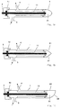
- the rigid optical shaft shown in Figures 1a to c 1 can be used as an introduction to the working channel an endoscope can be used.
- the optics shaft 1 carries a translucent at the distal end Scattered light dome 5, in which the optical waveguide 2 via a Introducer lock 12 is guided. Inside the optics shaft can form the scattering and cooling fluid, Litter liquid 21, which in the inlet 3 in Arrow direction are introduced and in a coaxial Cladding tube 11 to drain 4 - also in the direction of the arrow - circulate backwards.
- the stray light dome 5 can be rounded cylindrically (Figure 1a), conical (51 in Figure 1b) or with a lateral generated by deflection through a window 52 Beam direction (Figure 1c) be provided.
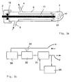
- FIG. 2 shows a device for circulating the cooling Scattered light liquid in an ultrasonic mixer and Reservoir 33 is homogenized, then via a thermostat 32, which has a temperature sensor in the return line 34 regulated and a pump 31 is supplied. Of the Secondary pressure of the pump is 35 in via a pressure switch the feed line 3 adjustable.
- FIG. 3a A further preferred embodiment is shown in FIG. 3a the invention in the form of a flexible optical shaft as Scattered light catheter shown.
- a flexible catheter tube 6 provided at the distal end with a optically transparent, limited elastic, dimensionally stable Membrane 7 is closed in the preformed pores 71 are introduced.
- the optical waveguide 2 is again introduced into the optical shaft via a lock 12.
- the Cooling stray liquid 21 is fed via an inlet 3 in inserted and flows the at least two-lumen catheter via the drain 4 to the supply devices.
- the associated supply devices are shown in FIG represented individual.
- the drain 4 is initially fed to a reservoir 36, from there via a thermostat 32, via a temperature sensor 34 in the return line is controlled by a pressure pump 31, which in turn is controlled by a pressure switch 35 in the inlet 3 becomes.
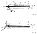
- FIG. 4a shows a further arrangement of the optical working shaft, in which the liquid to be evaporated is coaxial for laser light-transmitting fiber optics 2 in one coaxial enveloping body 11 to the distal end of the optical Working shaft 1 is introduced and due to the distal End of existing environmental or radiation induced Temperature is first evaporated as aerosol 22.
- the Aerosol 22 evaporates during the application process completely to the gas 23, which via an outlet port A is supplied to a condenser and as a liquid the inlet port E is fed back to the process.
- Figure 4b shows a compared to the embodiment according to Figure 4a simplified arrangement in which the evaporator liquid 20 via a thin hose element 15 to the advanced distal end of the optical working shaft 1 becomes. This is where aerosol and gas formation takes place instead, the resulting gas 23 then in turn via a Outlet connector of an external liquefaction device is fed.
- FIG. 5a shows the basic diagram of an external liquefaction device in the case of a low-boiling liquid, which are either already at room temperature or condensable with additional cooling in a condenser 37 and then again as a liquid via a pump 31 is fed to the process.
- the working point is about checked and adjusted a pressure switch 35.
- Figure 5b shows a further embodiment of the invention Arrangement in the event that as a litter and Cooling medium uses a gas liquefied under pressure becomes.
- the gas is first of all via a compressor 38 compressed and then liquefied in a condenser 37.
- the operating point is in turn via a pressure switch set.
- the laser radiation leading optical fiber 2 at the distal end tapering - or in some other way executed with a matt surface.
- This can preferably by immersing the protective coating Optical waveguide in an etching liquid and subsequent gradual extraction can be achieved. As a result becomes a graded at the end of the optical fiber Cone created with a matt surface.
- the scattering fluid thus contributes to one undirected distribution of the radiation, whereby also also the matting of the surface of the distal Contributes to the end of the translucent cathedral.
- geometric design is the prerequisite for achieving a desired intensity distribution the radiation in the application area.
- the intracorporeal use of a rigid invention or flexible optical shaft can either turn about the working shaft of an endoscope mentioned at the beginning take place or with a non-endoscopic procedure flexible catheter using a trocar or a conventional one Sluice, with applications in solid fabric first the way to the application site boughened with a stylet must become. Then instead of the stylet the light scattering catheter is inserted and then withdraw the introducer so far that it does not more in the effective range of the radiation.
Landscapes
- Health & Medical Sciences (AREA)
- Engineering & Computer Science (AREA)
- Biomedical Technology (AREA)
- Pathology (AREA)
- Nuclear Medicine, Radiotherapy & Molecular Imaging (AREA)
- Radiology & Medical Imaging (AREA)
- Life Sciences & Earth Sciences (AREA)
- Animal Behavior & Ethology (AREA)
- General Health & Medical Sciences (AREA)
- Public Health (AREA)
- Veterinary Medicine (AREA)
- Laser Surgery Devices (AREA)
- Radiation-Therapy Devices (AREA)
Description
Ferner ist die Abstrahlrichtung nicht steuerbar und somit die Wirkung nicht gleichzeitig visuell beobachtbar bzw. generell modifizierbar.
Der Erfindung liegt die Aufgabe zugrunde, bei einem Arbeitsschaft der eingangs genannten Gattung die Möglichkeit zu schaffen, ein Lichtbündel im Inneren des Körpers auf besonders einfache Weise derart zu applizieren, daß die Erwärmung im Nahbereich unzulässige Werte nicht überschreitet.
Insbesondere soll die thermische Behandlung in Intensität und Richtung in weiten Grenzen von außerhalb des Körpers beeinflußbar sein.
Claims (24)
- Optischer Arbeitsschaft, bei dem optische Strahlung höherer Leistung durch das distale Ende abstrahlbar ist, insbesondere zum Einführen in den Arbeitskanal eines Endoskops oder eines sonstigen Katheters, wobei für den Transport der Strahlung bis zum distalen Ende im wesentlichen ein optischer Wellenleiter (2) vorgesehen ist und wobei die Strahlung mindestens im distalen Bereich innerhalb eines Fluids (21) verläuft, das ein dispergierendes Medium ist, das den optischen Strahl beim Durchgang durch das Fluid (21) durch einen am distalen Ende befindlichen optischen Dom (5) hindurch streut, wobei der optische Dom (5) transparent für die optische Strahlung ist,
dadurch gekennzeichnet,
daß das dispergierende Fluid (21) im distalen Endbereich gleichzeitig eine Kühlflüssigkeit ist, die Verlustwarme abführt, die durch Streuung in der Nachbarschaft des distalen Endbereichs entsteht, und daß der Dom (5) aus einem opalisierenden Mineral oder opalisierenden Glas besteht. - Arbeitsschaft nach Anspruch 1, dadurch gekennzeichnet, daß Mittel zur unterschiedlichen Konzentration der Strahlung, entsprechend einer gewünschten Abstrahlcharakteristik, in Bezug auf die das distale Ende umgebenden Raumsegmente vorgesehen sind, welche insbesondere in der geometrischen Gestaltung (51) der Form des optischen Doms (5) bestehen.
- Arbeitsschaft nach Anspruch 2, dadurch gekennzeichnet, daß die Mittel zur unterschiedlichen Konzentration der Strahlung vom distalen Ende her bezüglich der Raumrichtung steuerbar sind.
- Arbeitsschaft nach Anspruch 3, dadurch gekennzeichnet, daß im Bereich des distalen Endes mindestens ein einstellbares Spiegelsegment (53) vorgesehen ist.
- Arbeitsschaft nach einem der vorangehenden Ansprüche, dadurch gekennzeichnet, daß das Fluid (21) einen Phasenstreuer bildet.
- Arbeitsschaft nach einem der vorangehenden Ansprüche, dadurch gekennzeichnet, daß Mittel zur Förderung des Kühlfluids koaxial zum Strahlung führenden Wellenleiter in Richtung auf das distale Ende vorgesehen sind.
- Arbeitsschaft nach einem der vorangehenden Ansprüche, dadurch gekennzeichnet, daß zur Kühlung und als optisch streuendes Fluid (21) eine Emulsion aus Öl, insbesondere Silikonöl, und Wasser und/oder als biokompatible Streuflüssigkeit eine Fett/Öl-Wasser-Emulsion-Infusionslösung vorgesehen ist.
- Arbeitsschaft nach Anspruch 7, dadurch gekennzeichnet, daß ein Ultraschallschwinger zum Mischen bzw. In-Mischung-halten der Emulsion aus Öl und Wasser vorgesehen ist.
- Arbeitsschaft nach Anspruch 8, dadurch gekennzeichnet, daß zur Stabilisierung der mittels Ultraschall erzeugten Emulsion eine Detergenz vorgesehen ist.
- Arbeitsschaft nach einem der vorangehenden Ansprüche, dadurch gekennzeichnet, daß als Fluid (21) eine leicht verdampfbare Flüssigkeit vorgesehen ist.
- Arbeitsschaft nach Anspruch 10, dadurch gekennzeichnet, daß es sich bei der verdampfbaren Flüssigkeit um Alkohol und/oder Fluorkohlenwasserstoff handelt.
- Arbeitsschaft nach einem der Ansprüche 10 oder 11, dadurch gekennzeichnet, daß die verdampfbare Flüssigkeit durch eine Kondensator-Pumpen bzw. Kompressor-Kondensator-Anordnung rekondensier- und als Flüssigkeit wiederum dem Prozeß zuführbar ist.
- Arbeitsschaft nach einem der Ansprüche 10 bis 12, dadurch gekennzeichnet, daß ein getrennter Schlauch bzw. ein Rohr zur Zuführung der verdampfbaren Flüssigkeit in die distale Verdampfungsregion vorgesehen ist.
- Arbeitsschaft nach einem der vorangehenden Ansprüche, dadurch gekennzeichnet, daß ein flexibler Katheter (6) als Führungsschaft für den optischen Lichtwellenleiter (2) zur Übertragung der Wirkstrahlung vorgesehen ist.
- Arbeitsschaft nach einem der vorangehenden Ansprüche, dadurch gekennzeichnet, daß die Temperatur des kühlenden und optisch streuenden Fluids (21) regelbar ist.
- Arbeitsschaft nach Anspruch 14, dadurch gekennzeichnet, daß der Katheter (6) an seinem distalen Ende mit einer optisch transparenten expandierbaren Verschlußkappe (7) versehen ist.
- Arbeitsschaft nach Anspruch 16, gekennzeichnet durch eine Drucksteuerung zur kontrollierten Expansion der Verschlußkappe (7).
- Arbeitsschaft nach einem der Ansprüche 16 oder 17, dadurch gekennzeichnet, daß als Material für die Verschlußkappe (7) eine formstabile, beschränkt elastische Kunststoffmembran vorgesehen ist.
- Arbeitsschaft nach einem der Anspruch 18, dadurch gekennzeichnet, daß die Kunststoffmembran der Verschlußkappe (7) präformierte Poren zum Flüssigkeitsaustritt aufweist.
- Arbeitsschaft nach einem der vorangehenden Ansprüche, dadurch gekennzeichnet, daß die Strahlung durch Laserstrahlung gebildet wird.
- Arbeitsschaft nach einem der vorangehenden Ansprüche, dadurch gekennzeichnet, daß der Wellenlängenbereich im wesentlichen 400 bis 1400 nm beträgt.
- Arbeitsschaft nach einem der vorangehenden Ansprüche, dadurch gekennzeichnet, daß das distale Ende des Lichtwellenleiters gestuft oder in sonstiger Weise sich zu seinem Ende hin verjüngend ausgebildet ist.
- Arbeitsschaft nach einem der vorangehenden Ansprüche, dadurch gekennzeichnet, daß der Lichtwellenleiter eine numerische Apertur von größer als 0,4 aufweist.
- Arbeitsschaft nach einem der vorangehenden Ansprüche, dadurch gekennzeichnet, daß der Lichtwellenleiter als Hohlleiter ausgebildet ist.
Applications Claiming Priority (5)
| Application Number | Priority Date | Filing Date | Title |
|---|---|---|---|
| DE4211526 | 1992-04-06 | ||
| DE19924211526 DE4211526A1 (de) | 1992-04-06 | 1992-04-06 | Optischer Arbeitsschaft zur Photo-Thermotherapie |
| DE4237286 | 1992-10-30 | ||
| DE4237286A DE4237286A1 (de) | 1992-04-06 | 1992-10-30 | Verfahren und Vorrichtung zur Effizienzsteigerung eines optischen Arbeitsschaftes zur Photo-Thermotherapie |
| PCT/DE1993/000321 WO1993019680A1 (de) | 1992-04-06 | 1993-04-02 | Arbeitsschaft für die photo-thermo-therapie |
Publications (2)
| Publication Number | Publication Date |
|---|---|
| EP0634909A1 EP0634909A1 (de) | 1995-01-25 |
| EP0634909B1 true EP0634909B1 (de) | 1998-08-19 |
Family
ID=25913708
Family Applications (1)
| Application Number | Title | Priority Date | Filing Date |
|---|---|---|---|
| EP93907786A Expired - Lifetime EP0634909B1 (de) | 1992-04-06 | 1993-04-02 | Arbeitsschaft für die photo-thermo-therapie |
Country Status (4)
| Country | Link |
|---|---|
| US (1) | US6039728A (de) |
| EP (1) | EP0634909B1 (de) |
| DE (2) | DE4237286A1 (de) |
| WO (1) | WO1993019680A1 (de) |
Cited By (2)
| Publication number | Priority date | Publication date | Assignee | Title |
|---|---|---|---|---|
| EP0891157A1 (de) | 1996-04-04 | 1999-01-20 | Somatex Medizintechnische Instrumente GmbH | Laserapplikationsset |
| CN102590926A (zh) * | 2012-03-02 | 2012-07-18 | 北京工业大学 | 高功率激光注入光纤的耦合装置 |
Families Citing this family (54)
| Publication number | Priority date | Publication date | Assignee | Title |
|---|---|---|---|---|
| US5908415A (en) * | 1994-09-09 | 1999-06-01 | Rare Earth Medical, Inc. | Phototherapy methods and apparatus |
| US5632767A (en) * | 1994-09-09 | 1997-05-27 | Rare Earth Medical, Inc. | Loop diffusers for diffusion of optical radiation |
| US5637877A (en) * | 1995-06-06 | 1997-06-10 | Rare Earth Medical, Inc. | Ultraviolet sterilization of instrument lumens |
| DE19725877B4 (de) * | 1997-06-18 | 2004-02-05 | Fraunhofer-Gesellschaft zur Förderung der angewandten Forschung e.V. | Applikationsvorrichtung zum Abtragen biologischen Gewebes |
| DE19914108A1 (de) * | 1999-03-23 | 2000-10-05 | Plasmaphotonics Gmbh | Bestrahlungsanordnung, insbesondere zur optischen Thermolyse |
| US9033961B2 (en) | 1999-07-14 | 2015-05-19 | Cardiofocus, Inc. | Cardiac ablation catheters for forming overlapping lesions |
| US8540704B2 (en) | 1999-07-14 | 2013-09-24 | Cardiofocus, Inc. | Guided cardiac ablation catheters |
| US8900219B2 (en) | 1999-07-14 | 2014-12-02 | Cardiofocus, Inc. | System and method for visualizing tissue during ablation procedures |
| SE515480C2 (sv) * | 1999-12-15 | 2001-08-13 | Permanova Lasersystem Ab | Metod och anordning för att mäta förlusteffekten i ett fiberoptiskt kontaktdon |
| DE10008557A1 (de) * | 2000-02-24 | 2001-10-25 | Huettinger Medtech Gmbh | Vorrichtung zur thermischen Behandlung von biologischen Gewebe |
| US6503268B1 (en) * | 2000-04-03 | 2003-01-07 | Ceramoptec Industries, Inc. | Therapeutic laser system operating between 1000nm and 1300nm and its use |
| US8256430B2 (en) | 2001-06-15 | 2012-09-04 | Monteris Medical, Inc. | Hyperthermia treatment and probe therefor |
| US6558410B1 (en) * | 2000-11-28 | 2003-05-06 | Remotelight, Inc. | Cardiac deblocking device and method |
| US8118732B2 (en) | 2003-04-01 | 2012-02-21 | Boston Scientific Scimed, Inc. | Force feedback control system for video endoscope |
| US20040199052A1 (en) | 2003-04-01 | 2004-10-07 | Scimed Life Systems, Inc. | Endoscopic imaging system |
| US7578786B2 (en) | 2003-04-01 | 2009-08-25 | Boston Scientific Scimed, Inc. | Video endoscope |
| US7591783B2 (en) | 2003-04-01 | 2009-09-22 | Boston Scientific Scimed, Inc. | Articulation joint for video endoscope |
| US20050245789A1 (en) | 2003-04-01 | 2005-11-03 | Boston Scientific Scimed, Inc. | Fluid manifold for endoscope system |
| US7270656B2 (en) * | 2003-11-07 | 2007-09-18 | Visualase, Inc. | Cooled laser fiber for improved thermal therapy |
| US7597662B2 (en) | 2004-09-30 | 2009-10-06 | Boston Scientific Scimed, Inc. | Multi-fluid delivery system |
| US8353860B2 (en) | 2004-09-30 | 2013-01-15 | Boston Scientific Scimed, Inc. | Device for obstruction removal with specific tip structure |
| US7479106B2 (en) | 2004-09-30 | 2009-01-20 | Boston Scientific Scimed, Inc. | Automated control of irrigation and aspiration in a single-use endoscope |
| US8083671B2 (en) | 2004-09-30 | 2011-12-27 | Boston Scientific Scimed, Inc. | Fluid delivery system for use with an endoscope |
| EP1799095A2 (de) | 2004-09-30 | 2007-06-27 | Boston Scientific Scimed, Inc. | Adapter zur verwendung mit einem digitalen bildgebenden medizinprodukt |
| JP2008514363A (ja) | 2004-09-30 | 2008-05-08 | ボストン サイエンティフィック リミテッド | 電気外科用途において使用するための多機能内視鏡システム |
| US7241263B2 (en) | 2004-09-30 | 2007-07-10 | Scimed Life Systems, Inc. | Selectively rotatable shaft coupler |
| US8097003B2 (en) | 2005-05-13 | 2012-01-17 | Boston Scientific Scimed, Inc. | Endoscopic apparatus with integrated variceal ligation device |
| US7846107B2 (en) | 2005-05-13 | 2010-12-07 | Boston Scientific Scimed, Inc. | Endoscopic apparatus with integrated multiple biopsy device |
| US20070049911A1 (en) * | 2005-08-26 | 2007-03-01 | Brown Joe D | Endovascular method and apparatus with feedback |
| US8052597B2 (en) | 2005-08-30 | 2011-11-08 | Boston Scientific Scimed, Inc. | Method for forming an endoscope articulation joint |
| DE202005017518U1 (de) * | 2005-11-04 | 2007-03-08 | Kämpfert, Marco | Stabendoskop |
| US7967759B2 (en) | 2006-01-19 | 2011-06-28 | Boston Scientific Scimed, Inc. | Endoscopic system with integrated patient respiratory status indicator |
| US8888684B2 (en) | 2006-03-27 | 2014-11-18 | Boston Scientific Scimed, Inc. | Medical devices with local drug delivery capabilities |
| US7955255B2 (en) | 2006-04-20 | 2011-06-07 | Boston Scientific Scimed, Inc. | Imaging assembly with transparent distal cap |
| US8202265B2 (en) | 2006-04-20 | 2012-06-19 | Boston Scientific Scimed, Inc. | Multiple lumen assembly for use in endoscopes or other medical devices |
| US9403029B2 (en) | 2007-07-18 | 2016-08-02 | Visualase, Inc. | Systems and methods for thermal therapy |
| US20090308433A1 (en) * | 2008-06-17 | 2009-12-17 | Waytronx, Inc. | Method and apparatus for cooling of solar power cells |
| US8728092B2 (en) | 2008-08-14 | 2014-05-20 | Monteris Medical Corporation | Stereotactic drive system |
| US8747418B2 (en) * | 2008-08-15 | 2014-06-10 | Monteris Medical Corporation | Trajectory guide |
| US8979871B2 (en) | 2009-08-13 | 2015-03-17 | Monteris Medical Corporation | Image-guided therapy of a tissue |
| US10335230B2 (en) | 2011-03-09 | 2019-07-02 | Covidien Lp | Systems for thermal-feedback-controlled rate of fluid flow to fluid-cooled antenna assembly and methods of directing energy to tissue using same |
| US20120232549A1 (en) * | 2011-03-09 | 2012-09-13 | Vivant Medical, Inc. | Systems for thermal-feedback-controlled rate of fluid flow to fluid-cooled antenna assembly and methods of directing energy to tissue using same |
| US10675113B2 (en) | 2014-03-18 | 2020-06-09 | Monteris Medical Corporation | Automated therapy of a three-dimensional tissue region |
| US20150265353A1 (en) | 2014-03-18 | 2015-09-24 | Monteris Medical Corporation | Image-guided therapy of a tissue |
| US9433383B2 (en) | 2014-03-18 | 2016-09-06 | Monteris Medical Corporation | Image-guided therapy of a tissue |
| WO2015167929A1 (en) | 2014-04-28 | 2015-11-05 | Cardiofocus, Inc. | System and method for visualizing tissue with an icg dye composition during ablation procedures |
| EP4295801A3 (de) * | 2014-05-05 | 2024-03-20 | Vicarious Surgical Inc. | Chirurgische virtual-reality-vorrichtung |
| WO2016089900A2 (en) | 2014-12-03 | 2016-06-09 | Cardiofocus, Inc. | System and method for visual confirmation of pulmonary vein isolation during ablation procedures |
| US10327830B2 (en) | 2015-04-01 | 2019-06-25 | Monteris Medical Corporation | Cryotherapy, thermal therapy, temperature modulation therapy, and probe apparatus therefor |
| US11172821B2 (en) | 2016-04-28 | 2021-11-16 | Medtronic Navigation, Inc. | Navigation and local thermometry |
| CN110290757B (zh) | 2016-12-16 | 2022-09-23 | 纳米光谱生物科学股份有限公司 | 用于消融治疗的装置及其使用方法 |
| US10067304B2 (en) * | 2016-12-20 | 2018-09-04 | Boston Scientific Scimed, Inc. | Fluid cooled optical fiber |
| WO2020191400A1 (en) * | 2019-03-21 | 2020-09-24 | The General Hospital Corporation | Systems and methods for catheter based light delivery |
| US10962727B2 (en) * | 2019-04-10 | 2021-03-30 | Lumentum Operations Llc | Optical fiber heat exchanger having parallel channels for optical fiber cooling |
Family Cites Families (23)
| Publication number | Priority date | Publication date | Assignee | Title |
|---|---|---|---|---|
| US4273109A (en) * | 1976-07-06 | 1981-06-16 | Cavitron Corporation | Fiber optic light delivery apparatus and medical instrument utilizing same |
| US4211229A (en) * | 1977-12-01 | 1980-07-08 | Richard Wolf Medical Instruments Corp. | Laser endoscope |
| US4470407A (en) * | 1982-03-11 | 1984-09-11 | Laserscope, Inc. | Endoscopic device |
| DE3323365C2 (de) * | 1982-09-04 | 1994-10-20 | Gsf Forschungszentrum Umwelt | Verfahren und Vorrichtung zur Ausleuchtung von Hohlräumen |
| JPH0741082B2 (ja) * | 1984-09-14 | 1995-05-10 | オリンパス光学工業株式会社 | レ−ザプロ−ブ |
| US4718417A (en) * | 1985-03-22 | 1988-01-12 | Massachusetts Institute Of Technology | Visible fluorescence spectral diagnostic for laser angiosurgery |
| JPS62170263A (ja) * | 1986-01-23 | 1987-07-27 | 森 敬 | 治療照射光插入具 |
| FR2597744A1 (fr) * | 1986-04-29 | 1987-10-30 | Boussignac Georges | Catheter cardio-vasculaire pour tir au rayon laser |
| DE3786206T2 (de) * | 1986-07-25 | 1993-10-21 | Kinki University Higashiosaka | Vorrichtung für Lichtkoagulation des morbiden Teiles. |
| SU1405805A1 (ru) * | 1986-08-11 | 1988-06-30 | Предприятие П/Я А-3903 | Устройство дл облучени световым излучением |
| NL8700329A (nl) * | 1987-02-11 | 1988-09-01 | Hoed Daniel Stichting | Inrichting en werkwijze voor het onderzoeken en/of belichten van een holle ruimte in een lichaam. |
| DE3833990C2 (de) * | 1987-05-25 | 1995-05-24 | Deutsche Aerospace | Ballonkatheter |
| DE3813227A1 (de) * | 1987-05-25 | 1989-01-12 | Messerschmitt Boelkow Blohm | Einrichtung zur zirkumferenziellen bestrahlung von objekten |
| SU1606128A1 (ru) * | 1988-08-12 | 1990-11-15 | Радиотехнический Институт Им.Акад А.Л.Минца | Устройство дл облучени труднодоступных участков организма |
| JPH03501809A (ja) * | 1988-08-23 | 1991-04-25 | ラディオテフニチェスキ インスティテュト イメニ アカデミカ アー.エル.ミンツァ アカデミイ ナウク エスエスエスエル | 光線療法用光ガイド装置 |
| JP2729275B2 (ja) * | 1988-10-05 | 1998-03-18 | 則雄 大工園 | レーザ光による加温装置 |
| EP0362767A1 (de) * | 1988-10-06 | 1990-04-11 | Lasag Ag | Monolithisches catadioptrisches Gerät |
| DE3901931A1 (de) * | 1989-01-24 | 1990-08-02 | Schott Glaswerke | Lichtleitfaser zur radiaeren bestrahlung von roehrenfoermigen hohlsystemen mit laserstrahlen |
| DE3941705C2 (de) * | 1989-12-18 | 1994-10-13 | Gsf Forschungszentrum Umwelt | Vorrichtung zur isotropen Bestrahlung von Hohlräumen von kugelähnlicher Gestalt |
| ES2067013T3 (es) * | 1990-01-09 | 1995-03-16 | Ciba Geigy Ag | Dispositivo para la irradiacion de los bronquios de un paciente para una terapia fotodinamica. |
| WO1993021841A1 (en) * | 1992-04-24 | 1993-11-11 | Surgical Laser Technologies, Inc. | Medical device |
| US5344419A (en) * | 1993-04-23 | 1994-09-06 | Wayne State University | Apparatus and method for making a diffusing tip in a balloon catheter system |
| US5429635A (en) * | 1994-07-13 | 1995-07-04 | Pioneer Optics Company | Fiberoptic spherical diffuser |
-
1992
- 1992-10-30 DE DE4237286A patent/DE4237286A1/de not_active Ceased
-
1993
- 1993-04-02 WO PCT/DE1993/000321 patent/WO1993019680A1/de not_active Ceased
- 1993-04-02 DE DE59308896T patent/DE59308896D1/de not_active Expired - Fee Related
- 1993-04-02 US US08/313,256 patent/US6039728A/en not_active Expired - Lifetime
- 1993-04-02 EP EP93907786A patent/EP0634909B1/de not_active Expired - Lifetime
Cited By (4)
| Publication number | Priority date | Publication date | Assignee | Title |
|---|---|---|---|---|
| EP0891157A1 (de) | 1996-04-04 | 1999-01-20 | Somatex Medizintechnische Instrumente GmbH | Laserapplikationsset |
| US6283958B1 (en) | 1996-04-04 | 2001-09-04 | Somatex Medizintechnische Instrumente Gmbh | Laser applicator set |
| CN102590926A (zh) * | 2012-03-02 | 2012-07-18 | 北京工业大学 | 高功率激光注入光纤的耦合装置 |
| CN102590926B (zh) * | 2012-03-02 | 2013-05-15 | 北京工业大学 | 高功率激光注入光纤的耦合装置 |
Also Published As
| Publication number | Publication date |
|---|---|
| US6039728A (en) | 2000-03-21 |
| EP0634909A1 (de) | 1995-01-25 |
| DE4237286A1 (de) | 1994-05-05 |
| DE59308896D1 (de) | 1998-09-24 |
| WO1993019680A1 (de) | 1993-10-14 |
Similar Documents
| Publication | Publication Date | Title |
|---|---|---|
| EP0634909A1 (de) | Arbeitsschaft für die photo-thermo-therapie | |
| DE69229128T2 (de) | Medizinische vorrichtung | |
| DE69514262T2 (de) | Katheter mit Lichtleitfaser | |
| DE4137983C2 (de) | Applikationsvorrichtung für die Behandlung biologischer Gewebe mit Laserstrahlung | |
| EP2004081B1 (de) | Laserapplikator | |
| EP0647152B1 (de) | Sonde zum erwärmen von körpergewebe | |
| DE69926348T2 (de) | System zur elektromagnetischen bestrahlung der haut | |
| DE69933504T2 (de) | Apparat zur Gewebebestrahlung | |
| DE69233647T2 (de) | Vorrichtung mit laserlichtdurchlässiger Nadel | |
| DE2145921C2 (de) | Einrichtung zur Materialbearbeitung durch ein Laserstrahlungsbündel mit einem biegsamen Lichtleiter | |
| DE69412406T2 (de) | Laser Ballonkatheter Vorrichtung | |
| DE69635430T2 (de) | Vorrichtung zur Entfernung von Haaren mit einer pulsierten elektromagnetischen Strahlung | |
| DE60130237T2 (de) | Lasertherapiegerät | |
| EP0697840A1 (de) | Verfahren und vorrichtung zur thermischen verödung biologischen gewebes | |
| DE10393938T5 (de) | Vorrichtung und Verfahren zur Zufuhr langwelliger Laserenergie an eine Gewebestelle | |
| DE4001086A1 (de) | Behandlungskatheter | |
| DE4416902A1 (de) | Medizinische Sondenvorrichtung mit optischem Sehvermögen | |
| DE10212366A1 (de) | Lichtdispersions-Sonde | |
| DE60031209T2 (de) | Laserbestrahlungsgerät | |
| EP0796131A1 (de) | Vorrichtung zum bestrahlen von körpergewebe mit laserlicht | |
| DE60115770T2 (de) | Medizinisches Bestrahlungsgerät | |
| EP3265013B1 (de) | Dentallaser zur behandlung von weichgewebe | |
| DE19821986C1 (de) | Laserinstrument | |
| DE69512748T2 (de) | Behandlungsvorrichtung für Körperhöhlen mit Laserenergie | |
| DE68926221T2 (de) | Medizinische anordnung zur anwendung von lokalisiertem licht und lokalisierter wärme hoher intensität, insbesondere zur vernichtung des endometriums |
Legal Events
| Date | Code | Title | Description |
|---|---|---|---|
| PUAI | Public reference made under article 153(3) epc to a published international application that has entered the european phase |
Free format text: ORIGINAL CODE: 0009012 |
|
| 17P | Request for examination filed |
Effective date: 19941028 |
|
| AK | Designated contracting states |
Kind code of ref document: A1 Designated state(s): DE FR GB IT |
|
| 17Q | First examination report despatched |
Effective date: 19960425 |
|
| RAP1 | Party data changed (applicant data changed or rights of an application transferred) |
Owner name: HUETTINGER MEDIZINTECHNIK GMBH & CO. KG Owner name: CERAMOPTEC GMBH |
|
| GRAG | Despatch of communication of intention to grant |
Free format text: ORIGINAL CODE: EPIDOS AGRA |
|
| GRAG | Despatch of communication of intention to grant |
Free format text: ORIGINAL CODE: EPIDOS AGRA |
|
| GRAH | Despatch of communication of intention to grant a patent |
Free format text: ORIGINAL CODE: EPIDOS IGRA |
|
| GRAH | Despatch of communication of intention to grant a patent |
Free format text: ORIGINAL CODE: EPIDOS IGRA |
|
| GRAA | (expected) grant |
Free format text: ORIGINAL CODE: 0009210 |
|
| AK | Designated contracting states |
Kind code of ref document: B1 Designated state(s): DE FR GB IT |
|
| RAP1 | Party data changed (applicant data changed or rights of an application transferred) |
Owner name: HUETTINGER MEDIZINTECHNIK GMBH & CO. KG Owner name: CERAMOPTEC GMBH |
|
| REF | Corresponds to: |
Ref document number: 59308896 Country of ref document: DE Date of ref document: 19980924 |
|
| GBT | Gb: translation of ep patent filed (gb section 77(6)(a)/1977) |
Effective date: 19981116 |
|
| ET | Fr: translation filed | ||
| PLBE | No opposition filed within time limit |
Free format text: ORIGINAL CODE: 0009261 |
|
| 26N | No opposition filed | ||
| REG | Reference to a national code |
Ref country code: GB Ref legal event code: IF02 |
|
| PGFP | Annual fee paid to national office [announced via postgrant information from national office to epo] |
Ref country code: DE Payment date: 20070502 Year of fee payment: 15 |
|
| PGFP | Annual fee paid to national office [announced via postgrant information from national office to epo] |
Ref country code: GB Payment date: 20070425 Year of fee payment: 15 |
|
| PGFP | Annual fee paid to national office [announced via postgrant information from national office to epo] |
Ref country code: IT Payment date: 20070523 Year of fee payment: 15 |
|
| PGFP | Annual fee paid to national office [announced via postgrant information from national office to epo] |
Ref country code: FR Payment date: 20070330 Year of fee payment: 15 |
|
| GBPC | Gb: european patent ceased through non-payment of renewal fee |
Effective date: 20080402 |
|
| PG25 | Lapsed in a contracting state [announced via postgrant information from national office to epo] |
Ref country code: DE Free format text: LAPSE BECAUSE OF NON-PAYMENT OF DUE FEES Effective date: 20081101 |
|
| REG | Reference to a national code |
Ref country code: FR Ref legal event code: ST Effective date: 20081231 |
|
| PG25 | Lapsed in a contracting state [announced via postgrant information from national office to epo] |
Ref country code: FR Free format text: LAPSE BECAUSE OF NON-PAYMENT OF DUE FEES Effective date: 20080430 |
|
| PG25 | Lapsed in a contracting state [announced via postgrant information from national office to epo] |
Ref country code: GB Free format text: LAPSE BECAUSE OF NON-PAYMENT OF DUE FEES Effective date: 20080402 |
|
| PG25 | Lapsed in a contracting state [announced via postgrant information from national office to epo] |
Ref country code: IT Free format text: LAPSE BECAUSE OF NON-PAYMENT OF DUE FEES Effective date: 20080402 |