EP0632961A1 - Conche - Google Patents
Conche Download PDFInfo
- Publication number
- EP0632961A1 EP0632961A1 EP94108660A EP94108660A EP0632961A1 EP 0632961 A1 EP0632961 A1 EP 0632961A1 EP 94108660 A EP94108660 A EP 94108660A EP 94108660 A EP94108660 A EP 94108660A EP 0632961 A1 EP0632961 A1 EP 0632961A1
- Authority
- EP
- European Patent Office
- Prior art keywords
- trough
- rotor
- rotors
- screw
- conching
- Prior art date
- Legal status (The legal status is an assumption and is not a legal conclusion. Google has not performed a legal analysis and makes no representation as to the accuracy of the status listed.)
- Granted
Links
- 238000005520 cutting process Methods 0.000 claims abstract description 18
- 235000019219 chocolate Nutrition 0.000 claims description 20
- 239000002674 ointment Substances 0.000 claims description 9
- 238000007790 scraping Methods 0.000 claims description 9
- 230000010006 flight Effects 0.000 claims description 2
- 238000004901 spalling Methods 0.000 claims 1
- 244000299461 Theobroma cacao Species 0.000 description 18
- 230000000694 effects Effects 0.000 description 8
- 239000000463 material Substances 0.000 description 8
- 238000004898 kneading Methods 0.000 description 5
- 238000002156 mixing Methods 0.000 description 5
- 238000003825 pressing Methods 0.000 description 4
- 230000033001 locomotion Effects 0.000 description 3
- 238000012545 processing Methods 0.000 description 3
- 241000237858 Gastropoda Species 0.000 description 2
- 238000004090 dissolution Methods 0.000 description 2
- 230000002349 favourable effect Effects 0.000 description 2
- 238000000034 method Methods 0.000 description 2
- 239000011295 pitch Substances 0.000 description 2
- 230000008569 process Effects 0.000 description 2
- 238000010186 staining Methods 0.000 description 2
- 235000016127 added sugars Nutrition 0.000 description 1
- 230000002730 additional effect Effects 0.000 description 1
- 238000005054 agglomeration Methods 0.000 description 1
- QVGXLLKOCUKJST-UHFFFAOYSA-N atomic oxygen Chemical compound [O] QVGXLLKOCUKJST-UHFFFAOYSA-N 0.000 description 1
- TZCXTZWJZNENPQ-UHFFFAOYSA-L barium sulfate Chemical compound [Ba+2].[O-]S([O-])(=O)=O TZCXTZWJZNENPQ-UHFFFAOYSA-L 0.000 description 1
- 230000015572 biosynthetic process Effects 0.000 description 1
- 230000008859 change Effects 0.000 description 1
- 229940110456 cocoa butter Drugs 0.000 description 1
- 235000019868 cocoa butter Nutrition 0.000 description 1
- 230000007423 decrease Effects 0.000 description 1
- 238000013461 design Methods 0.000 description 1
- 235000019197 fats Nutrition 0.000 description 1
- 239000010419 fine particle Substances 0.000 description 1
- 235000003599 food sweetener Nutrition 0.000 description 1
- 239000004615 ingredient Substances 0.000 description 1
- 230000003993 interaction Effects 0.000 description 1
- 238000004519 manufacturing process Methods 0.000 description 1
- 239000000203 mixture Substances 0.000 description 1
- 229910052760 oxygen Inorganic materials 0.000 description 1
- 239000001301 oxygen Substances 0.000 description 1
- 239000002245 particle Substances 0.000 description 1
- 230000009467 reduction Effects 0.000 description 1
- 238000005096 rolling process Methods 0.000 description 1
- 239000003765 sweetening agent Substances 0.000 description 1
- 238000012360 testing method Methods 0.000 description 1
- 238000012549 training Methods 0.000 description 1
- 238000012546 transfer Methods 0.000 description 1
Images

Classifications
-
- A—HUMAN NECESSITIES
- A23—FOODS OR FOODSTUFFS; TREATMENT THEREOF, NOT COVERED BY OTHER CLASSES
- A23G—COCOA; COCOA PRODUCTS, e.g. CHOCOLATE; SUBSTITUTES FOR COCOA OR COCOA PRODUCTS; CONFECTIONERY; CHEWING GUM; ICE-CREAM; PREPARATION THEREOF
- A23G1/00—Cocoa; Cocoa products, e.g. chocolate; Substitutes therefor
- A23G1/04—Apparatus specially adapted for manufacture or treatment of cocoa or cocoa products
- A23G1/14—Longitudinal conches, i.e. rollers being in a backward and forward motion
Definitions
- the invention relates to a conche with at least two rotors, each arranged in a trough part of a conching trough, according to the preamble of claim 1.
- the invention has for its object to a conche of the aforementioned, conventional type, as in the last.
- the above-mentioned document is shown to improve the kneading and ointment of the mass while avoiding agglomerates or tubers, as can arise, for example, from various ingredients, and thus shorten the, often considerable, conching time.
- the knife rotor is designed as a screw rotor and - compared to conventional extruder screws - is driven at an increased speed of at least 1000 revolutions, preferably 1500 to 3000 revolutions, and thus brings in a relatively high degree of energy.
- the at least one knife rotor is provided in a trough part arranged deeper in the conching trough than the trough part for the at least one rotor equipped with blades and optionally also with scraping and ointment tools.
- the trough part arranged lower in the conching trough for the worm rotor upwards, in the direction of one or more trough parts arranged higher, the rotor equipped with blades results in an extremely intensive material exchange between the individual trough parts, which advantageously contributes to the increase in quality.
- the at least one cutting tool driven to rotate within the trough is designed as a sharp cutting edge on the screw helix of a screw rotor; that, furthermore, the cutting edge is optionally arranged to run radially, but preferably extends over the circumference, or that cutting tools projecting therefrom are provided between the flights of the screw helix, or the screw helix is interrupted at least at one point to form radially running cutting edges, because of the dissolution of agglomerates, which results from added sugar or sweetener, for example, is particularly advantageous for homogenizing the chocolate mass.
- a cutting edge is provided on the worm rotor itself, in particular is formed by a worm helix which extends parallel to the other rotors, instead of transversely thereto, this enables an uninterrupted scraper formation over the length of the respective trough part, as is the case on the wings of the respective other rotor is preferably provided.
- the screw helix can also have different pitches, the distance between the screw helical tunnels, preferably towards the inside of the conching trough, being increasingly narrow, also brings about quality-enhancing additional effects in the mixing, kneading and staining of the chocolate mass. Working times for mixing, kneading and staining are significantly reduced in an economically advantageous manner.
- At least one screw or knife rotor or the associated trough part extends only over a portion of the overall length of the conching trough. This advantageously increases the pressure of the material within the trough part occupied by the screw rotor.
- the trough part of the knife or worm rotor in the interior of the conching trough and its end wall opposite is closed off by a transverse wall or inclined transverse wall perpendicular to the rotor axis, which is preferably also provided for mounting the worm rotor.
- the pressing effect is strongly supported by arranging this transverse wall.
- the inclined transverse wall advantageously directs the material to the tools of the rotor equipped with blades.
- the conche works particularly effectively in a preferred embodiment according to the invention in which the length of the knife or screw rotor is at least a quarter, at most half, preferably a third of the overall length of the conching trough.
- a plurality of knife or worm rotors are arranged, according to a further preferred embodiment of the invention, these are provided opposite one another in the axial direction and / or preferably parallel to one another.
- Multiple screw rotors are particularly advantageous if they are shorter than the length of the conching trough. It is quite conceivable to design these screw rotors in the manner of twin screw extruders. Here, trough parts which are completely separate from one another but also merge into one another can be formed.
- the advantageous function of the conche according to the invention is particularly given when the axes of all the rotors are preferably arranged at least approximately parallel to one another.
- a, preferably, common motor drive direction is provided for all rotors, and that that direction of rotation of each rotor equipped with blades and preferably with scraping and ointment tools is provided, the chocolate mass from above to the trough part or each knife or screw rotor promotes.
- an effective and simply constructed speed control of all rotors can be achieved and the direction of flow of the material for the work processes can be set or controlled effectively.
- the knife or screw rotor in the sense of the invention is certainly operated at high speed, which is rather unusual for screws in the conveying or pressing device.
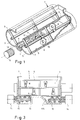
- a trough 1 is provided, the inner wall 2 of which is designed to form three trough parts 3, 4 and 5 which are clearly separated from one another.
- Every trough compartment each closely encloses one of the rotors, of which two rotors 6, 7 are only partially and schematically shown in FIG. 1.
- the rotors 6 and 7 are conventionally equipped with radially projecting vanes, of which vanes 8, preferably with openings provided therein, serve for the mixture, whereas vanes 9 are designed with scraping and ointment tools at their end, which tools interact with the respective trough wall 2 . Since all the rotors extend parallel to one another, these scraping or ointmenting tools can be designed continuously or continuously over the entire length of the trough.
- the tools 9 act as spatula tools in the direction of rotation of the left rotor and as spatula tools in the direction of rotation of the right rotor.
- This illustration only serves to illustrate the functions, because in normal cases the alignment on both rotors will be the same, so that the tools 9 of both rotors (if a change in the direction of rotation is provided) act as a spatula tool in one direction of rotation and as a splicing tool in the other direction.
- the worm rotor 10 can also be provided with radially extending cutting edges, for example by a section of its length being occupied by such cutting tools or by the fact that cutting tools protrude between the coils of the rotor 10.
- a special embodiment can consist in that the helix 12 is interrupted at one or more points 13 to form radially extending cutting edges. Such interruptions also promote the mixing effect.
- the rotors 6, 7 and 10 are driven in a conventional manner from the outside, only one motor 14 being shown in FIG. 1, which could also drive the other rotors 6 and 7 via a corresponding gear, but is expedient for a separate motor drive is provided for each rotor 6, 7 and 10.
- the trough part 4 receiving the screw rotor 10 does not have a filling opening in the end facing the trough wall, as would be conceivable per se, but in the manner clearly shown in FIG Top is open. This results in a more intensive exchange of chocolate mass between the individual trough parts 3 to 5.
- the screw helix 12 has a different pitch over its length, for example has narrower helices against its end facing the wall 15.
- the wall 15 allows the screw rotor 10 to be stored therein, so that it can be supported on the outer trough wall on the one hand and on the transverse wall 15 on the other hand.
- the chocolate material pressed out of the trough part 4 by the pressing of the screw rotor 10 is expediently stripped off by the blades 8 with the scraping tools 9 and thus passes from the trough part 4 into the trough part 3, where it is subjected to further processing. It can be seen that the axial movement of the screw rotor 10 results in an even more intensive mixing because this axial movement is still superimposed on the movement of the mass between the individual trough parts 3 to 5.
- FIG. 1 and 2 show a screw rotor 10 which extends only over part of the length of the trough 1, it is entirely possible within the scope of the invention to provide a screw rotor which takes up the entire length of the trough.
- transverse wall 15 which transverse wall is expediently arranged at a distance from the front wall of the trough which corresponds to at least a quarter, preferably a third, possibly half the length of the trough 1. Accordingly, there remains a certain trough length in which no worm rotor would come into effect, which is why it is advantageous according to FIG. 3 to arrange at least one second worm 10 from the opposite side of the trough 1.
- the wall 15 is preferably approximately perpendicular to the axis of the screw rotor 10, but if necessary in the sense of the wall 115 shown in FIG. 3 can be at an angle to the axis of the rotor 10 that deviates from 90 °.
- the trough wall forms a separate compartment 4, 4 'in the area of the two screw rotors 10, 10', the trough wall forming a lying 3 on the underside.
- both screw rotors 10, 10 'in a common trough part although this is not preferred.
- the wall 115 could represent the intake wall for the material and the wall in FIG. 3 on the right, perpendicular to the axis of the rotor 10, may limit the outlet gap through which the material is pressed out.
- worm rotor (s) 10 are shown in the center on the underside of the trough 1, which is preferred, it would also be possible within the scope of the invention to arrange them, for example, on one side or halfway up or at the top of the trough.
Landscapes
- Life Sciences & Earth Sciences (AREA)
- Chemical & Material Sciences (AREA)
- Engineering & Computer Science (AREA)
- Food Science & Technology (AREA)
- Polymers & Plastics (AREA)
- Confectionery (AREA)
- Medicines That Contain Protein Lipid Enzymes And Other Medicines (AREA)
- Display Devices Of Pinball Game Machines (AREA)
- Ink Jet (AREA)
- Peptides Or Proteins (AREA)
- Cosmetics (AREA)
Applications Claiming Priority (3)
| Application Number | Priority Date | Filing Date | Title |
|---|---|---|---|
| CH202393 | 1993-07-06 | ||
| CH2023/93 | 1993-07-06 | ||
| CH202393 | 1993-07-06 |
Publications (2)
| Publication Number | Publication Date |
|---|---|
| EP0632961A1 true EP0632961A1 (fr) | 1995-01-11 |
| EP0632961B1 EP0632961B1 (fr) | 1999-08-04 |
Family
ID=4224112
Family Applications (1)
| Application Number | Title | Priority Date | Filing Date |
|---|---|---|---|
| EP94108660A Expired - Lifetime EP0632961B1 (fr) | 1993-07-06 | 1994-06-07 | Conche |
Country Status (5)
| Country | Link |
|---|---|
| US (1) | US5505542A (fr) |
| EP (1) | EP0632961B1 (fr) |
| JP (1) | JPH07143852A (fr) |
| AT (1) | ATE182748T1 (fr) |
| DE (1) | DE59408571D1 (fr) |
Cited By (3)
| Publication number | Priority date | Publication date | Assignee | Title |
|---|---|---|---|---|
| WO2011092230A1 (fr) * | 2010-01-28 | 2011-08-04 | Bühler AG | Mélangeur à surface d'impact |
| EP2596855A1 (fr) * | 2011-10-26 | 2013-05-29 | Zaklady Urzadzen Kotlowych Staporkow Spolka Akcyjna | Dispositif de mélange de matériaux énergétique, en particulier de biomasse, déchet, poussière de charbon et optionnel boutisse |
| WO2019048686A1 (fr) * | 2017-09-11 | 2019-03-14 | Rinsch Edelstahlverarbeitung Gmbh | Procédé et dispositif de fabrication d'un produit de cacao ou de chocolat |
Families Citing this family (20)
| Publication number | Priority date | Publication date | Assignee | Title |
|---|---|---|---|---|
| DE19743470A1 (de) * | 1997-10-01 | 1999-04-08 | Buehler Ag | Verfahren und Vorrichtung zum Vorkonditionieren des in einem Extruder zu verarbeitenden Produktes und dgl. |
| US7857500B2 (en) * | 2003-08-20 | 2010-12-28 | Kraft Foods Global Brands Llc | Apparatus for vacuum-less meat processing |
| US8172545B2 (en) * | 2003-08-20 | 2012-05-08 | Kraft Foods Global Brands Llc | Method for controlling ground meat flow rates |
| US7871655B2 (en) * | 2003-08-20 | 2011-01-18 | Kraft Foods Global Brands Llc | Method and apparatus for accelerating formation of functional meat mixtures |
| US20050249862A1 (en) * | 2003-08-20 | 2005-11-10 | Kraft Foods Holdings, Inc. | Method and apparatus for controlling texture of meat products |
| US7488502B2 (en) * | 2003-08-20 | 2009-02-10 | Kraft Foods Global Brands Llc | Method of making processed meat products |
| US20050255222A1 (en) * | 2003-08-20 | 2005-11-17 | Kraft Foods Holdings, Inc. | Method and apparatus for acceleration ingredient diffusion in meat |
| US7731998B2 (en) * | 2003-08-20 | 2010-06-08 | Kraft Foods Global Brands Llc | Method for reducing protein exudate on meat product |
| US20050276903A1 (en) * | 2003-08-20 | 2005-12-15 | Kraft Foods Holdings, Inc. | Method and apparatus for meat product manufacturing |
| US20050255224A1 (en) * | 2003-08-20 | 2005-11-17 | Kraft Foods Holdings, Inc. | Integrated continuous meat processing system |
| US7169421B2 (en) * | 2003-08-20 | 2007-01-30 | Kraft Foods Holdings, Inc. | Method of making processed meat products |
| KR100593671B1 (ko) * | 2005-01-11 | 2006-06-30 | 삼광식품공업 주식회사 | 콘칭 장치 |
| GB2422327A (en) * | 2005-01-25 | 2006-07-26 | George Martin Gale | Thermoplastic laboratory mixer |
| US8308342B2 (en) | 2008-11-24 | 2012-11-13 | Kraft Foods Global Brands Llc | Processing elements for mixing meat products |
| US8641263B2 (en) | 2008-11-24 | 2014-02-04 | Kraft Foods Group Brands Llc | Method and apparatus for continuous processing of whole muscle meat products |
| US8187651B2 (en) * | 2008-11-24 | 2012-05-29 | Kraft Foods Global Brands Llc | Method and apparatus for continuous processing of whole muscle meat products |
| IT1399691B1 (it) * | 2010-03-30 | 2013-04-26 | Soremartec Sa | Metodo per la preparazione di un semilavorato dolciario, ad esempio tipo cioccolato o similare |
| US8919285B1 (en) * | 2012-09-21 | 2014-12-30 | Greg Chambers | Portable livestock feed storage and delivery device |
| USD869789S1 (en) * | 2017-04-19 | 2019-12-10 | Rotecna, S.A. | Machine for processing animal feed |
| NL2021128B1 (en) * | 2018-06-15 | 2019-12-20 | Eco Habitat B V | Process to bacterially decompose organic waste |
Citations (3)
| Publication number | Priority date | Publication date | Assignee | Title |
|---|---|---|---|---|
| CH405910A (de) * | 1961-04-27 | 1966-01-15 | Heidenau Maschf Veb | Maschine zum kontinuierlichen Mischen, insbesondere von Bestandteilen der Schokolade |
| EP0518025A2 (fr) * | 1991-05-02 | 1992-12-16 | Richard Frisse Gmbh Maschinenfabrik | Conche et procédé de mise en oeuvre de celle-ci |
| EP0565887A1 (fr) * | 1992-04-14 | 1993-10-20 | R. FRISSE GmbH | Machine pour travailler des masses de chocolat et son application à la fabrication de crumbs |
Family Cites Families (20)
| Publication number | Priority date | Publication date | Assignee | Title |
|---|---|---|---|---|
| US561298A (en) * | 1896-06-02 | Beating and mixing machine for confectionersj use | ||
| US506384A (en) * | 1893-10-10 | Machine for beating and mixing sirup | ||
| DE288770C (fr) * | ||||
| US1603546A (en) * | 1924-04-09 | 1926-10-19 | Kirschbraun Lester | Apparatus for making emulsions |
| SU138191A1 (ru) * | 1960-09-28 | 1960-11-30 | Г.М. Пономарев | Шнековый грохот |
| DE1189368B (de) * | 1963-04-24 | 1965-03-18 | Richard Frisse Maschinenfabrik | Conchiermaschine fuer Schokoladenmassen od. dgl. |
| DE1298083B (de) * | 1966-02-25 | 1969-06-26 | Metallgesellschaft Ag | Schneckenmaschine |
| US3421740A (en) * | 1966-10-31 | 1969-01-14 | Norman A Behrens | Material mixer |
| US3797807A (en) * | 1971-09-13 | 1974-03-19 | Creston Mfg Co Inc | Material mixer |
| US3995836A (en) * | 1975-01-30 | 1976-12-07 | Veda, Inc. | Material mixing and feeding apparatus |
| SU626801A1 (ru) * | 1976-07-05 | 1978-08-15 | Северодонецкий Филиал Всесоюзного Научно-Исследовательского И Конструкторского Института Химического Машиностроения | Смеситель |
| US4269582A (en) * | 1978-11-21 | 1981-05-26 | Mario Mella | Pasta-making machine |
| US4462693A (en) * | 1980-01-25 | 1984-07-31 | Veda, Inc. | Material mixing apparatus |
| DE3215273A1 (de) * | 1982-04-23 | 1983-10-27 | Bayer Ag, 5090 Leverkusen | Vorrichtung zum austragen hochviskoser medien in der chemischen verfahrenstechnik |
| US4707140A (en) * | 1986-09-29 | 1987-11-17 | Mohrlang Manufacturing, Inc. | Feed mixer |
| DE3731907A1 (de) * | 1987-09-23 | 1989-04-13 | Pumpen Und Maschinenbau Fritz | Vorrichtung fuer die aufgabe von foerdergut auf eine exzenterschneckenpumpe |
| DE4021305C2 (de) * | 1990-07-04 | 2003-07-31 | Barry Callebaut Ag Zuerich | Vorrichtung zum kontinuierlichen Conchieren von Schokolademasse |
| US5148999A (en) * | 1991-01-11 | 1992-09-22 | Farm Shop, Inc. | Animal feed mixing system |
| DE4125629A1 (de) * | 1991-08-02 | 1993-02-04 | Buehler Ag | Conche |
| US5372418A (en) * | 1992-11-19 | 1994-12-13 | Polymer Processing Institute | Back mix drag-flow apparatus |
-
1994
- 1994-06-07 AT AT94108660T patent/ATE182748T1/de not_active IP Right Cessation
- 1994-06-07 DE DE59408571T patent/DE59408571D1/de not_active Expired - Fee Related
- 1994-06-07 EP EP94108660A patent/EP0632961B1/fr not_active Expired - Lifetime
- 1994-06-27 US US08/266,197 patent/US5505542A/en not_active Expired - Fee Related
- 1994-07-05 JP JP6153807A patent/JPH07143852A/ja not_active Withdrawn
Patent Citations (3)
| Publication number | Priority date | Publication date | Assignee | Title |
|---|---|---|---|---|
| CH405910A (de) * | 1961-04-27 | 1966-01-15 | Heidenau Maschf Veb | Maschine zum kontinuierlichen Mischen, insbesondere von Bestandteilen der Schokolade |
| EP0518025A2 (fr) * | 1991-05-02 | 1992-12-16 | Richard Frisse Gmbh Maschinenfabrik | Conche et procédé de mise en oeuvre de celle-ci |
| EP0565887A1 (fr) * | 1992-04-14 | 1993-10-20 | R. FRISSE GmbH | Machine pour travailler des masses de chocolat et son application à la fabrication de crumbs |
Cited By (5)
| Publication number | Priority date | Publication date | Assignee | Title |
|---|---|---|---|---|
| WO2011092230A1 (fr) * | 2010-01-28 | 2011-08-04 | Bühler AG | Mélangeur à surface d'impact |
| EP2353707A1 (fr) * | 2010-01-28 | 2011-08-10 | Bühler AG | Mélangeur doté d'une chicane |
| JP2013517933A (ja) * | 2010-01-28 | 2013-05-20 | ビューラー・アクチエンゲゼルシャフト | 跳ね当て面を備えたミキサ |
| EP2596855A1 (fr) * | 2011-10-26 | 2013-05-29 | Zaklady Urzadzen Kotlowych Staporkow Spolka Akcyjna | Dispositif de mélange de matériaux énergétique, en particulier de biomasse, déchet, poussière de charbon et optionnel boutisse |
| WO2019048686A1 (fr) * | 2017-09-11 | 2019-03-14 | Rinsch Edelstahlverarbeitung Gmbh | Procédé et dispositif de fabrication d'un produit de cacao ou de chocolat |
Also Published As
| Publication number | Publication date |
|---|---|
| US5505542A (en) | 1996-04-09 |
| JPH07143852A (ja) | 1995-06-06 |
| DE59408571D1 (de) | 1999-09-09 |
| EP0632961B1 (fr) | 1999-08-04 |
| ATE182748T1 (de) | 1999-08-15 |
Similar Documents
| Publication | Publication Date | Title |
|---|---|---|
| EP0632961B1 (fr) | Conche | |
| EP0160124B1 (fr) | Pétrisseuse à double vis sans fin, tournant dans le même sens, avec disques de pétrissage | |
| DE69737118T2 (de) | Doppelschneckenkneter | |
| DE602005000098T2 (de) | Dynamische Durchfluss-Mischvorrichtung | |
| EP0329092A1 (fr) | Mélangeur-pétrin à plusieurs arbres | |
| DE2550969C2 (de) | Schneckenmaschine zum Homogenisieren von festen, flüssigen und zähviskosen Materialien | |
| DE3242641A1 (de) | Kontinuierlich arbeitende granuliervorrichtung | |
| EP0565887A1 (fr) | Machine pour travailler des masses de chocolat et son application à la fabrication de crumbs | |
| EP3473396A1 (fr) | Arbre de vis sans fin à deux ailettes pour machine de mélange et de pétrissage | |
| EP0422272B2 (fr) | Dispositif de malaxage et pétrissage | |
| DE3101083C2 (de) | Kontinuierlich arbeitender Mischer mit zwei parallelen Mischkammern | |
| DE2432860C2 (de) | Vorrichtung zum kontinuierlichen Dispergieren und Feinmahlen von Feststoffen in einem flüssigen Dispersionsmittel | |
| DE10207145A1 (de) | Vorrichtung zum Dispergieren und Aufschmelzen fließfähiger Stoffe | |
| DE2513577C3 (de) | Kontinuierlich arbeitender Mischer für plastische Massen | |
| AT517755A1 (de) | Vorrichtung und Verfahren zur Verarbeitung von thermoplastischem Kunststoff mit einer verbesserten Zerkleinerungs-/Transportvorrichtung | |
| EP0564884B1 (fr) | Machine avec plusieurs arbres à vis avec pompe d'engrenage | |
| DE3920422A1 (de) | Mischvorrichtung fuer mehrkomponentenkunststoffe | |
| EP0914773A1 (fr) | Appareil de traitement de masses contenant du beurre de cacao ou une graisse analogue, en particulier des masses de chocolat | |
| EP0941031A1 (fr) | Dispositif pour traiter des produits alimentaires ou du fourrage | |
| DE69908471T2 (de) | Kontinuierlich arbeitende Knetmaschine | |
| DE3344297A1 (de) | Vorrichtung zum extrudieren von kunstharzen | |
| DE3603155A1 (de) | Conche | |
| DE4115583A1 (de) | Mehrfachschneckenextruder | |
| EP0248196B1 (fr) | Dispositif comportant plusieurs vis sans fin s'engrènant mutuellement et comportant des éléments de coupe | |
| DE3905946A1 (de) | Vorrichtung zum kontinuierlichen herstellen von speiseeis |
Legal Events
| Date | Code | Title | Description |
|---|---|---|---|
| PUAI | Public reference made under article 153(3) epc to a published international application that has entered the european phase |
Free format text: ORIGINAL CODE: 0009012 |
|
| AK | Designated contracting states |
Kind code of ref document: A1 Designated state(s): AT BE CH DE DK ES FR GB GR IE IT LI LU NL PT SE |
|
| 17P | Request for examination filed |
Effective date: 19941216 |
|
| 17Q | First examination report despatched |
Effective date: 19960614 |
|
| GRAG | Despatch of communication of intention to grant |
Free format text: ORIGINAL CODE: EPIDOS AGRA |
|
| GRAG | Despatch of communication of intention to grant |
Free format text: ORIGINAL CODE: EPIDOS AGRA |
|
| GRAH | Despatch of communication of intention to grant a patent |
Free format text: ORIGINAL CODE: EPIDOS IGRA |
|
| GRAH | Despatch of communication of intention to grant a patent |
Free format text: ORIGINAL CODE: EPIDOS IGRA |
|
| ITF | It: translation for a ep patent filed | ||
| GRAA | (expected) grant |
Free format text: ORIGINAL CODE: 0009210 |
|
| AK | Designated contracting states |
Kind code of ref document: B1 Designated state(s): AT BE CH DE DK ES FR GB GR IE IT LI LU NL PT SE |
|
| PG25 | Lapsed in a contracting state [announced via postgrant information from national office to epo] |
Ref country code: SE Free format text: THE PATENT HAS BEEN ANNULLED BY A DECISION OF A NATIONAL AUTHORITY Effective date: 19990804 Ref country code: NL Free format text: LAPSE BECAUSE OF FAILURE TO SUBMIT A TRANSLATION OF THE DESCRIPTION OR TO PAY THE FEE WITHIN THE PRESCRIBED TIME-LIMIT Effective date: 19990804 Ref country code: GR Free format text: LAPSE BECAUSE OF NON-PAYMENT OF DUE FEES Effective date: 19990804 Ref country code: GB Free format text: LAPSE BECAUSE OF FAILURE TO SUBMIT A TRANSLATION OF THE DESCRIPTION OR TO PAY THE FEE WITHIN THE PRESCRIBED TIME-LIMIT Effective date: 19990804 Ref country code: FR Free format text: LAPSE BECAUSE OF FAILURE TO SUBMIT A TRANSLATION OF THE DESCRIPTION OR TO PAY THE FEE WITHIN THE PRESCRIBED TIME-LIMIT Effective date: 19990804 Ref country code: ES Free format text: THE PATENT HAS BEEN ANNULLED BY A DECISION OF A NATIONAL AUTHORITY Effective date: 19990804 |
|
| REF | Corresponds to: |
Ref document number: 182748 Country of ref document: AT Date of ref document: 19990815 Kind code of ref document: T |
|
| REG | Reference to a national code |
Ref country code: CH Ref legal event code: EP |
|
| REF | Corresponds to: |
Ref document number: 59408571 Country of ref document: DE Date of ref document: 19990909 |
|
| REG | Reference to a national code |
Ref country code: IE Ref legal event code: FG4D Free format text: GERMAN |
|
| PG25 | Lapsed in a contracting state [announced via postgrant information from national office to epo] |
Ref country code: PT Free format text: LAPSE BECAUSE OF FAILURE TO SUBMIT A TRANSLATION OF THE DESCRIPTION OR TO PAY THE FEE WITHIN THE PRESCRIBED TIME-LIMIT Effective date: 19991104 Ref country code: DK Free format text: LAPSE BECAUSE OF FAILURE TO SUBMIT A TRANSLATION OF THE DESCRIPTION OR TO PAY THE FEE WITHIN THE PRESCRIBED TIME-LIMIT Effective date: 19991104 |
|
| EN | Fr: translation not filed | ||
| NLV1 | Nl: lapsed or annulled due to failure to fulfill the requirements of art. 29p and 29m of the patents act | ||
| GBV | Gb: ep patent (uk) treated as always having been void in accordance with gb section 77(7)/1977 [no translation filed] |
Effective date: 19990804 |
|
| PLBE | No opposition filed within time limit |
Free format text: ORIGINAL CODE: 0009261 |
|
| STAA | Information on the status of an ep patent application or granted ep patent |
Free format text: STATUS: NO OPPOSITION FILED WITHIN TIME LIMIT |
|
| PG25 | Lapsed in a contracting state [announced via postgrant information from national office to epo] |
Ref country code: LU Free format text: LAPSE BECAUSE OF NON-PAYMENT OF DUE FEES Effective date: 20000607 Ref country code: AT Free format text: LAPSE BECAUSE OF NON-PAYMENT OF DUE FEES Effective date: 20000607 |
|
| PG25 | Lapsed in a contracting state [announced via postgrant information from national office to epo] |
Ref country code: IE Free format text: LAPSE BECAUSE OF NON-PAYMENT OF DUE FEES Effective date: 20000621 |
|
| PG25 | Lapsed in a contracting state [announced via postgrant information from national office to epo] |
Ref country code: LI Free format text: LAPSE BECAUSE OF NON-PAYMENT OF DUE FEES Effective date: 20000630 Ref country code: CH Free format text: LAPSE BECAUSE OF NON-PAYMENT OF DUE FEES Effective date: 20000630 Ref country code: BE Free format text: LAPSE BECAUSE OF NON-PAYMENT OF DUE FEES Effective date: 20000630 |
|
| REG | Reference to a national code |
Ref country code: IE Ref legal event code: FD4D |
|
| 26N | No opposition filed | ||
| BERE | Be: lapsed |
Owner name: BUHLER A.G. Effective date: 20000630 |
|
| REG | Reference to a national code |
Ref country code: CH Ref legal event code: PL |
|
| PG25 | Lapsed in a contracting state [announced via postgrant information from national office to epo] |
Ref country code: DE Free format text: LAPSE BECAUSE OF NON-PAYMENT OF DUE FEES Effective date: 20010501 |
|
| PG25 | Lapsed in a contracting state [announced via postgrant information from national office to epo] |
Ref country code: IT Free format text: LAPSE BECAUSE OF NON-PAYMENT OF DUE FEES Effective date: 20050607 |