EP0630657A1 - Cathéter de matière plastique pliable - Google Patents
Cathéter de matière plastique pliable Download PDFInfo
- Publication number
- EP0630657A1 EP0630657A1 EP94108025A EP94108025A EP0630657A1 EP 0630657 A1 EP0630657 A1 EP 0630657A1 EP 94108025 A EP94108025 A EP 94108025A EP 94108025 A EP94108025 A EP 94108025A EP 0630657 A1 EP0630657 A1 EP 0630657A1
- Authority
- EP
- European Patent Office
- Prior art keywords
- catheter
- deflectable
- guide tube
- region
- channel
- Prior art date
- Legal status (The legal status is an assumption and is not a legal conclusion. Google has not performed a legal analysis and makes no representation as to the accuracy of the status listed.)
- Granted
Links
Images


Classifications
-
- A—HUMAN NECESSITIES
- A61—MEDICAL OR VETERINARY SCIENCE; HYGIENE
- A61M—DEVICES FOR INTRODUCING MEDIA INTO, OR ONTO, THE BODY; DEVICES FOR TRANSDUCING BODY MEDIA OR FOR TAKING MEDIA FROM THE BODY; DEVICES FOR PRODUCING OR ENDING SLEEP OR STUPOR
- A61M25/00—Catheters; Hollow probes
- A61M25/01—Introducing, guiding, advancing, emplacing or holding catheters
- A61M25/0105—Steering means as part of the catheter or advancing means; Markers for positioning
- A61M25/0133—Tip steering devices
- A61M25/0141—Tip steering devices having flexible regions as a result of using materials with different mechanical properties
-
- A—HUMAN NECESSITIES
- A61—MEDICAL OR VETERINARY SCIENCE; HYGIENE
- A61M—DEVICES FOR INTRODUCING MEDIA INTO, OR ONTO, THE BODY; DEVICES FOR TRANSDUCING BODY MEDIA OR FOR TAKING MEDIA FROM THE BODY; DEVICES FOR PRODUCING OR ENDING SLEEP OR STUPOR
- A61M25/00—Catheters; Hollow probes
- A61M25/0043—Catheters; Hollow probes characterised by structural features
-
- A—HUMAN NECESSITIES
- A61—MEDICAL OR VETERINARY SCIENCE; HYGIENE
- A61M—DEVICES FOR INTRODUCING MEDIA INTO, OR ONTO, THE BODY; DEVICES FOR TRANSDUCING BODY MEDIA OR FOR TAKING MEDIA FROM THE BODY; DEVICES FOR PRODUCING OR ENDING SLEEP OR STUPOR
- A61M25/00—Catheters; Hollow probes
- A61M25/01—Introducing, guiding, advancing, emplacing or holding catheters
- A61M25/0105—Steering means as part of the catheter or advancing means; Markers for positioning
- A61M25/0133—Tip steering devices
- A61M25/0136—Handles therefor
-
- A—HUMAN NECESSITIES
- A61—MEDICAL OR VETERINARY SCIENCE; HYGIENE
- A61M—DEVICES FOR INTRODUCING MEDIA INTO, OR ONTO, THE BODY; DEVICES FOR TRANSDUCING BODY MEDIA OR FOR TAKING MEDIA FROM THE BODY; DEVICES FOR PRODUCING OR ENDING SLEEP OR STUPOR
- A61M25/00—Catheters; Hollow probes
- A61M25/01—Introducing, guiding, advancing, emplacing or holding catheters
- A61M25/0105—Steering means as part of the catheter or advancing means; Markers for positioning
- A61M25/0133—Tip steering devices
- A61M25/0147—Tip steering devices with movable mechanical means, e.g. pull wires
-
- A—HUMAN NECESSITIES
- A61—MEDICAL OR VETERINARY SCIENCE; HYGIENE
- A61M—DEVICES FOR INTRODUCING MEDIA INTO, OR ONTO, THE BODY; DEVICES FOR TRANSDUCING BODY MEDIA OR FOR TAKING MEDIA FROM THE BODY; DEVICES FOR PRODUCING OR ENDING SLEEP OR STUPOR
- A61M25/00—Catheters; Hollow probes
- A61M25/01—Introducing, guiding, advancing, emplacing or holding catheters
- A61M25/06—Body-piercing guide needles or the like
- A61M25/0662—Guide tubes
Definitions
- the invention relates to a catheter with at least one hollow channel or lumen running inside, which catheter is essentially formed by a flexible plastic tube, the distal end of the catheter being arranged over the essential length of the catheter by means of an eccentrically arranged relative to its axial center Pulling element for more or less strong bending and thereby for controlling the tip of the catheter for entry into branches of the body cavity system, for example blood vessels, is elastically bendable or deflectable and the pulling element is enclosed by its own guide up to the deflectable area, this being the case Traction element and its guidance runs within the outline of the cross section of the catheter.
- catheters have been used in the medical field, which essentially consist of a plastic tube and have one or more channels (lumens) running in the longitudinal direction.
- stiffness there are differences in these catheters depending on the type of application, that is to say that the catheters can be very flexible but also very stiff or have an intermediate stiffness level, which usually means that with the stiffness Torsional stability grows.
- the distal end is often preformed so that the tip can be controlled to a limited extent by twisting the catheter.
- Guide wires are known for soft catheters, which are inserted into the body in front of the actual catheter and advanced to the destination. The actual catheters are then pushed over these guide wires.
- Instruments biopsy forceps
- pharmaceuticals and pharmaceuticals can also be inserted and applied through a channel of the controllable catheter.
- Probes provided with electrodes can also be inserted through the channel of the catheter in order, for example, to sense electrical potentials at the heart or to perform a high-frequency ablation.
- Liquid can also be aspirated through the lumen of the catheter, impurities can be removed or instruments of a diagnostic, surgical or therapeutic nature can be introduced.
- a catheter of the type mentioned at the outset which allows the tip to be controlled by an eccentrically arranged pulling wire.
- the Guide for this pull wire in a laterally offset in relation to the rest of the outline of the catheter, placed parallel to the actual catheter bead and at the end of this bead, the pull wire emerges freely and grips the opposite end of the catheter to deform it by the tensile force can.
- the guidewire which is partially and especially exposed in the distal end, can be dangerous especially when used in the heart and especially when used in the ventricle, since the heart valves in particular could be damaged by this wire.
- the additional bead running along the catheter is to be regarded as unfavorable for the production and also the handling, because the corresponding part of the catheter has different flexibility in different directions.
- a catheter in particular made of soft or flexible material, there is the risk that when the pulling element is actuated, not only the controllable tip, but the catheter will be curved over its entire length.
- the invention is therefore based on the object to provide a catheter of the type mentioned, with which a curvature of the catheter part leading to the flexible area is avoided by the actuation of the pulling element, but nevertheless the pulling element does not cause any risk of injury in the flexible area and one against the Catheter cross section protruding bead is avoided.
- the catheter therefore has a continuously circumferential cross-section, on which no projecting bead for receiving the tension element is arranged. Rather, it is housed within this cross section of the catheter.
- reinforcement is then also provided within the catheter cross-section, which stiffens the non-deflectable area to such an extent that when the tension element is actuated, only the controllable or flexible area is deflected in a desired manner, while the remaining part of the catheter is desirably is not bent. Due to the stiffening, but flexible reinforcement mentioned, the catheter is nevertheless made so flexible overall that it can also be inserted through blood vessels without any problems. Nevertheless, when the manipulator for the pulling element is activated, the catheter is curved only on the movable or bendable tip and not over its entire length.
- a particularly expedient arrangement of its own inventive importance can consist in that the reinforcement is a guide tube made of metal or hard plastic which accommodates the tension element, which extends within the outer cross section of the catheter up to the deflectable area and ends where that to the distal end of the deflectable area outgoing tension element emerges from the guide tube.
- the traction element is actuated, for example, by a manipulator, that is to say a tensile force is exerted, only the deflectable region is bent, because in the remaining region the region of the catheter that is reinforced by this, although flexible but essentially resistant, is prevented from bending.
- the deflectable area is essential due to its softness can be bent more easily than the area provided with the guide tube. It is advantageous that the tension element continues within the outline of the deflectable area up to its attachment point.
- the guide tube accommodating the pulling element can have an outer diameter of approximately one third or two fifths of a millimeter to approximately one millimeter and an inner diameter of approximately one fifth to approximately four fifths of a millimeter. Thus, it takes up so little space within the catheter that it can be accommodated well within the outline of the catheter and a bulge protruding from the outside of the outline can be avoided.
- the cross section or diameter of the tension element in particular of a tension wire, thread or ribbon, can be provided with a play of approximately one hundredth to approximately one tenth of a millimeter with respect to the inner cross section of the guide tube.
- the guide tube for the tension element can consist of stainless steel and the tension element can preferably be a wire, metal thread or metal strip.
- the guide tube can be flattened so that it requires even less space in the radial direction within the catheter if the longer cross-sectional axis of this flat tube and the larger width of the cross-section of the metal band are arranged approximately in the circumferential direction of the catheter.
- the plastic tube can have a greater wall thickness at least in the area of the arrangement of the guide tube for the pulling element than in the wall area approximately opposite on a diameter, and the guide tube can be at least partially embedded in the thickened wall area. In this way, its stiffening effect can be transferred well to the catheter wall. Still it is Guide tube with the traction element housed within the outer contour of the catheter. In the thickened wall area, at least one additional channel, in particular with a smaller cross section, can run parallel to the guide tube in addition to the inner channel. The thickening of the wall for accommodating the guide tube can therefore be used to provide at least one further channel, so that, for example, an instrument or endoscope or the like can be supplied through the inner channel of larger cross-section and a medicament can be supplied through this second channel.
- a modified embodiment of the invention can consist in that the catheter is formed from two nested plastic tubes, the outer tube forming the tight outer sheath, and in that the inner tube in its longitudinal direction at a distance from each other radially inwardly directed clamping fingers, retaining tongues or tabs for fixing or pinching the inner guide tube for the tension element.
- the guide tube is not embedded in a thickened wall of the catheter, but is held on the inside by corresponding tabs, fingers or the like.
- the holding tongues or the like of the inner tube can hold a further tube as an additional channel in addition to the flattened guide tube.
- a further tube in addition to the main channel, another parallel channel with a smaller cross section is possible.
- the flattening of the tubes causes the smallest possible cross-sectional narrowing of the inner channel of the catheter, into which the retaining tongues and the like protrude somewhat for the fixing of the guide tube.
- a modified version of the solution according to the invention which in turn has its own inventive significance, can consist in the fact that as a reinforcement parallel to the eccentrically arranged tension element on the opposite side with a diameter approximately another tension element is permanently installed, which up to the beginning of the flexible area runs and is attached there. If a pulling force is now exerted on the movable pulling element, the pulling element lying opposite it in the diameter in the catheter prevents this catheter area from bending or curving, so that in turn only the deflectable area of the catheter is curved in the desired manner.
- This arrangement could additionally be combined with a guide tube which accommodates the movable pulling element, in order to still better prevent its deformation when the deflectable region is curved if the catheter region is sufficiently flexible.
- a tensile element as reinforcement has the advantage that it practically does not impair the flexibility of the catheter itself, which is advantageous when it is inserted into blood vessels.
- the tube forming the catheter can have a wall of approximately constant thickness and on one side on a diameter opposite sides, on the one hand, a channel for the tension element that can be moved to bend and, on the other hand, a channel for the non-displaceable area that leads to the deflectable area and there ending traction element in particular a solid wire or a tape, for example made of metal.
- At least one additional channel can be arranged in the wall of the catheter as an additional lumen parallel to the channels for tension element and reinforcement.
- central or main channel another channel of smaller internal cross-section can be accommodated.
- the tension element in the deflectable area can likewise be guided in a separate channel, but without stiffening or reinforcement.
- the pulling element could also simply run inside the deflectable region and a channel present there, embedding in a channel surrounding the pulling element has the advantage that it does not come into contact with instruments or medication or the like inserted through this channel.
- the guide channel for the pulling element in the deflectable area has a transition area leading radially outward relative to the guide tube by its wall thickness, and the pulling element in the deflectable area is approximately the distance from the central axis of the catheter that the axis-distant surface line of the Has guide tube.
- the pulling element is moved radially outwards in the deflectable area as far as possible, in order to be able to exert the best possible curvature on this deflectable area, while within the guide tube the wall thickness of which leads to a somewhat more internal course of this pulling element, but where deflection occurs is prevented by the reinforcement.
- the tension element runs as far as possible on the outside of the swiveling area in order to be able to carry out a shape curved up to 180 degrees, that is to say a semicircular curvature of this area.
- the catheter can have sufficient flexibility, for example, to be able to be inserted into blood vessels and through their curvatures, but is so stiffened that the actuation of the pulling element is not leads to a curvature of the entire catheter, but only affects the deflectable and controllable catheter tip. Nevertheless, the catheter can have a constant cross-sectional circumference not changed by a protruding bead and a pull wire lying in the deflectable area with a risk of injury is avoided.
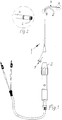
- a controllable catheter designated as a whole by 1, has, according to FIG. 1, a rotary manipulator 2 and, in a modified embodiment according to FIG. 9, a thrust manipulator 3, with which a deflectable region 4 with the aid of the manipulators and a tension element 5 running inside the catheter 1 or catheter shaft according to FIG Figure 1 is more or less flexible and thereby controllable. Electrodes 6 provided on this deflectable region 4 or on the distal tip of the catheter 1 can thus be positioned in a desired manner.
- the catheter 1 has a hollow channel 7 (lumen) through which instruments, therapy devices, endoscopes or the like can be inserted.
- the already mentioned tension element 5 is arranged eccentrically with respect to the axial center of the catheter 1, so that a force exerted on the tension element 5 with the aid of one of the manipulators results in a corresponding deflection of the deflectable area at the distal end of the catheter 1. This allows the tip of the catheter 1 to be manipulated and controlled in such a way that entry into branches of the body cavity system is facilitated.
- the tension element 5 is enclosed by a guide in a manner to be described.
- the plastic tube forming the catheter 1 has a continuous cross-section, in the exemplary embodiment a circular cross-section, that is to say no bead protruding laterally to accommodate the actual cross-section Tension element 5 is present.
- the cross section could also be oval or elliptical.
- the tension element 5 and its guide run within this outline of the cross section of the catheter 1, as shown in the figures. So that only the deflectable area 4 and not the entire catheter 1 is bent or curved during a pull on the pull element, up to this deflectable or flexible area 4 of the catheter, a reinforcement stiffening the catheter 1 with respect to its deflectable area is parallel to the pull element 5 also provided within the cross section of the catheter. Especially in the case of a relatively soft material, it is achieved in this way that only the deflectable, flexible region 4 is curved when the tensile element 5 is pulled, because the tensile force encounters the least resistance there. The remaining part of the catheter remains largely undeformed in the desired manner, but at the same time retains sufficient flexibility to be able to be inserted into body cavities or blood vessels and also to be able to participate in certain curvatures and bends.
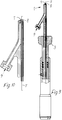
- the reinforcement is a guide tube 8 made of metal or hard plastic which accommodates the tensile element 5 and which extends within the outer cross section of the catheter 1 up to the deflectable region 4, as can be clearly seen in FIG Figure 3 recognizes.
- the guide tube 8 thus ends at the beginning of the deflectable region 4, where the pulling element 5, which continues towards the distal end of the deflectable region 4, therefore exits the guide tube 8. It then continues to run within the outline of the catheter and thereby the deflectable region 4 up to its attachment point at the distal end of this deflectable region 4.
- the deflectable area is curved to the side on which the pulling element runs inside this deflectable area 4 due to the eccentric arrangement, while at the same time the part of the catheter 1 having the guide tube 8 also largely as far as possible remains undeformed when the plastic tube forming the catheter 1 is relatively soft.
- the manipulators 2 and 3 each have an inlet opening 9, which is connected to the lumen or inner channel 7 of the catheter 1 and through which corresponding instrument, further catheters, electrodes, endoscopes or other parts or medication or the like can be introduced.
- the guide tube 8 receiving the pulling element has a relatively small outer diameter of approximately one millimeter or even less, possibly even only approximately 0.4 millimeters or even less and an inner diameter of approximately 0.2 to 0.8 millimeters, that is to say a wall thickness of, for example, a tenth of a millimeter. Nevertheless, the catheter 1 passing through it can be adequately stiffened to prevent it from being bent when the deflectable region is curved by actuating the pulling element 5. On the other hand, it does not hinder insertion of the catheter 1 even if it is elastically bent.
- the cross section or diameter of the tension element 5 can be provided in the interior of the guide tube with a play of approximately one hundredth to approximately one tenth of a millimeter with respect to the inner cross section, which is sufficient for a smooth movement of the tension element 5 in the guide tube 8, regardless of whether the tension element 5 retracted by a manipulator to bend or by the restoring force of the deflectable area 4 is moved again in the opposite direction.
- the guide tube 8 for the tension element 5 consists of stainless steel in order to be corrosion-resistant and insensitive to body fluids or medication, even if it is embedded in the wall of the catheter 1.
- the pulling element 5 can be a wire or metal thread or a metal band, which is correspondingly flat and thus allows an arrangement within the catheter 1 with a very small radial space requirement.
- the plastic tube which essentially forms the catheter 1
- the plastic tube has a greater wall thickness in the area of the accommodation of the guide tube 8 for the pulling element 5 than in the wall area approximately opposite on a diameter.
- the guide tube 8 is embedded in this thickened wall area.
- the inner channel 7 maintains a regular cross-sectional shape, which in the exemplary embodiment is circular, although this channel 7 is somewhat offset laterally relative to the geometric center of the catheter 1 or the tube forming it.
- two additional inner channels 10 with a smaller cross section than the actual main channel 7 are arranged adjacent to the guide tube 8, in order, for example, to be able to guide wires for electrode poles or the like or thermistors and medicines.
- the thickened wall area for embedding the guide tube 8 can thus be used to accommodate further channels separate from the actual inner channel 7.
- FIGS. 7 and 8 show a modified embodiment of the catheter 1, with only sections or cutouts in each case this catheter 1 can be seen in a diagrammatic and cut representation.
- the catheter 1 is formed from two nested plastic tubes 11 and 12, the outer tube 11 forming the tight outer sheath and the inner tube 12 in its longitudinal direction at a distance from one another in a row next to each other with radially inwardly directed clamping fingers, retaining tongues or tabs 13 for fixing or clamping the inner guide tube 8 for the tension element 5. These tabs 13 can be partially punched out of this inner plastic tube 12 and deformed in its inner cross section.
- these holding tongues or tabs 13 of the inner tube 12 can hold a further tube 14 as an additional channel in addition to the flattened guide tube 8 in this case.
- a further channel that is independent of the actual lumen or channel 7 can also be provided with this catheter design.
- the tubes 8 and 14 can also be formed by a double tube which is flattened.
- FIG. 6 A modified type of stiffening or reinforcement of the catheter 1 is shown in FIG. 6. It is now provided that a further tension element 15 is permanently installed as reinforcement parallel to the eccentrically arranged tension element 5 on the side approximately opposite a diameter, which tension element extends to the beginning of the flexible area 4 and is fastened there. If the movable pulling element 5 is actuated in the sense of a curvature of the deflectable area 4, this additional pulling element 15 prevents a curvature of the non-deflectable area of the catheter 1. It thus acts as a kind of counter pulling element. Thus, the movable and controlling pulling element 5 can be in a in the wall of the catheter 1st arranged channel run.
- both a guide tube 8 and such an additional tension element 15 are provided together as reinforcements.
- the counter-pull element 15 is shown thicker than the movable pull element 5 in FIG. 6; however, it can have the same thickness as tension element 5 or, if necessary, even be thinner.
- the tube forming the catheter 1 in this exemplary embodiment has a wall of approximately constant thickness and on one side on a diameter opposite sides, on the one hand a channel for the tensile element 5 which can be moved for bending and on the other hand a channel for the non-displaceable, up to the deflectable region 4 leading and ending there tension element 15, in particular a solid wire or a tape, for example made of metal, contains.
- tension element 15 in particular a solid wire or a tape, for example made of metal, contains.
- further channels 10 are in turn arranged as additional lumens in the wall of this catheter 1.
- the guide channel 16 for the pulling element 5 in the deflectable area 4 of the catheter 1 is radial with respect to the guide tube 8 by its wall thickness leading to the outside transition area 17, so that the tension element 8 can really be moved as far as possible to the outside of this movable area 4 in order to be able to bring about a curvature under the largest possible lever arm.
- the tension element 5 has in this deflectable area 4 according to Figure 3 approximately the distance from the central axis of the catheter 1, which the distal surface line of the guide tube 8 has from this center. It can be seen in FIG. 3 that the tension element is deflected slightly further outwards in the transition region 17 and then continues approximately as an extension of the outer wall of the guide tube 8.
- a catheter 1 results, which is formed from a plastic tube and has a corresponding flexibility and adaptability in order to be able to be inserted well into body cavity systems, in particular into blood vessels.
- Its deflectable area 4 can be manipulated with the aid of the inner tension element 5 without the tension element 5 having to emerge from the catheter 1 or the deflectable area 4 at any point. Nevertheless, a curvature of the part of the catheter 1 that is not to be deflected is avoided by a reinforcement, which can be a guide tube for enclosing the pulling element 5 or a further pulling element 15 opposite in diameter.
- the deflectable region 4 is curved by up to 180 ° or even beyond it, without the rest of the catheter shaft also being undesirably curved.
- the catheter 1 which is formed by a flexible plastic tube, has a hollow channel 7 in its interior and a deflectable region 4 at its distal end in order to be able to be controlled, for example, by blood vessels when inserted into branches.
- the catheter 1 has a regular circular, oval or elliptical cross section and the pulling element 5 and its guide are accommodated within the outline of this cross section.
- the catheter 1 has an up to the deflectable or flexible area 4 running approximately parallel to the tension element 5, but stiffening the non-deflectable area somewhat flexible reinforcement also within the cross section of the catheter.
- This reinforcement can be a guide tube 8 made of metal or hard plastic which receives the tension element 5 as a guide and / or a further tension element 15 which is permanently installed parallel to the movable tension element 5 on an approximately opposite diameter side of the catheter and only extends to the deflectable area 4.
Applications Claiming Priority (2)
| Application Number | Priority Date | Filing Date | Title |
|---|---|---|---|
| DE4320962 | 1993-06-24 | ||
| DE4320962A DE4320962C2 (de) | 1993-06-24 | 1993-06-24 | Katheter aus einem biegsamen Kunststoffschlauch |
Publications (2)
| Publication Number | Publication Date |
|---|---|
| EP0630657A1 true EP0630657A1 (fr) | 1994-12-28 |
| EP0630657B1 EP0630657B1 (fr) | 1999-07-28 |
Family
ID=6491100
Family Applications (1)
| Application Number | Title | Priority Date | Filing Date |
|---|---|---|---|
| EP94108025A Expired - Lifetime EP0630657B1 (fr) | 1993-06-24 | 1994-05-25 | Cathéter de matière plastique pliable |
Country Status (5)
| Country | Link |
|---|---|
| US (1) | US5484407A (fr) |
| EP (1) | EP0630657B1 (fr) |
| AT (1) | ATE182477T1 (fr) |
| DE (2) | DE4320962C2 (fr) |
| ES (1) | ES2134291T3 (fr) |
Cited By (18)
| Publication number | Priority date | Publication date | Assignee | Title |
|---|---|---|---|---|
| EP0689851A1 (fr) * | 1994-07-01 | 1996-01-03 | Cordis Europa N.V. | Cathéter flexible dirigeable |
| WO1997027895A1 (fr) * | 1996-02-02 | 1997-08-07 | Kelleher Brian S | Dispositif medical pouvant etre cintre |
| NL1002254C2 (nl) * | 1996-02-06 | 1997-08-07 | Cordis Europ | Bestuurd buigbare catheter. |
| EP0815895A1 (fr) * | 1996-06-03 | 1998-01-07 | Terumo Kabushiki Kaisha | Appareil medical tubulaire |
| WO1999033509A1 (fr) * | 1997-12-30 | 1999-07-08 | Cardima, Inc. | Sonde-guide susceptible de s'inflechir |
| US6413228B1 (en) | 1998-12-28 | 2002-07-02 | Pro Duct Health, Inc. | Devices, methods and systems for collecting material from a breast duct |
| WO2005018729A1 (fr) * | 2003-08-16 | 2005-03-03 | Dr. Osypka Gmbh | Cathéter à extrémité souple pouvant être courbée ou déviée |
| US7550001B2 (en) | 2001-04-30 | 2009-06-23 | C. R. Bard, Inc. | Stent delivery device and method for stent delivery |
| US7935141B2 (en) | 2005-08-17 | 2011-05-03 | C. R. Bard, Inc. | Variable speed stent delivery system |
| US8025692B2 (en) | 2001-10-02 | 2011-09-27 | Angiomed Gmbh & Co. Medizintechnik Kg | Stent delivery system |
| US8062344B2 (en) | 2001-04-30 | 2011-11-22 | Angiomed Gmbh & Co. Medizintechnik Kg | Variable speed self-expanding stent delivery system and luer locking connector |
| US8075606B2 (en) | 2001-07-06 | 2011-12-13 | Angiomed Gmbh & Co. Medizintechnik Kg | Delivery system having a rapid pusher assembly for self-expanding stent, and stent exchange configuration |
| US8475515B2 (en) | 2003-01-15 | 2013-07-02 | Angiomed GmbH & Co., Medizinitechnik KG | Trans-luminal surgical device |
| US8500789B2 (en) | 2007-07-11 | 2013-08-06 | C. R. Bard, Inc. | Device for catheter sheath retraction |
| US8808346B2 (en) | 2006-01-13 | 2014-08-19 | C. R. Bard, Inc. | Stent delivery system |
| US9078779B2 (en) | 2006-08-07 | 2015-07-14 | C. R. Bard, Inc. | Hand-held actuator device |
| US9801745B2 (en) | 2010-10-21 | 2017-10-31 | C.R. Bard, Inc. | System to deliver a bodily implant |
| US11026822B2 (en) | 2006-01-13 | 2021-06-08 | C. R. Bard, Inc. | Stent delivery system |
Families Citing this family (112)
| Publication number | Priority date | Publication date | Assignee | Title |
|---|---|---|---|---|
| US5658253A (en) * | 1995-02-21 | 1997-08-19 | Abbott Laboratories | Stylet device for guiding an enteral feeding tube |
| CA2197415A1 (fr) * | 1996-02-29 | 1997-08-29 | Kenneth C. Musgrave | Catheter avec une ailette repliee amelioree |
| US5810807A (en) * | 1996-05-22 | 1998-09-22 | Ganz; Robert A. | Sphincterotome with deflectable cutting plane and method of using the same |
| US20060074442A1 (en) * | 2000-04-06 | 2006-04-06 | Revascular Therapeutics, Inc. | Guidewire for crossing occlusions or stenoses |
| US20050119615A1 (en) * | 2000-04-06 | 2005-06-02 | Norborn Medical, Inc. | Guidewire for crossing occlusions or stenoses |
| US6059767A (en) * | 1998-02-25 | 2000-05-09 | Norborn Medical, Inc. | Steerable unitary infusion catheter/guide wire incorporating detachable infusion port assembly |
| US20080140101A1 (en) * | 2006-12-07 | 2008-06-12 | Revascular Therapeutic, Inc. | Apparatus for crossing occlusions or stenoses |
| US20070225615A1 (en) * | 2006-03-22 | 2007-09-27 | Revascular Therapeutics Inc. | Guidewire controller system |
| US9254143B2 (en) * | 1998-02-25 | 2016-02-09 | Revascular Therapeutics, Inc. | Guidewire for crossing occlusions or stenoses having a shapeable distal end |
| US6746422B1 (en) | 2000-08-23 | 2004-06-08 | Norborn Medical, Inc. | Steerable support system with external ribs/slots that taper |
| US6824550B1 (en) | 2000-04-06 | 2004-11-30 | Norbon Medical, Inc. | Guidewire for crossing occlusions or stenosis |
| IL123646A (en) * | 1998-03-11 | 2010-05-31 | Refael Beyar | Remote control catheterization |
| US6055457A (en) * | 1998-03-13 | 2000-04-25 | Medtronic, Inc. | Single pass A-V lead with active fixation device |
| DE19826746C1 (de) * | 1998-06-16 | 1999-11-25 | Sulzer Osypka Gmbh | Katheter mit zusätzlichem Handgriff |
| US6251079B1 (en) * | 1998-09-30 | 2001-06-26 | C. R. Bard, Inc. | Transthoracic drug delivery device |
| US6544215B1 (en) | 1998-10-02 | 2003-04-08 | Scimed Life Systems, Inc. | Steerable device for introducing diagnostic and therapeutic apparatus into the body |
| US7972323B1 (en) * | 1998-10-02 | 2011-07-05 | Boston Scientific Scimed, Inc. | Steerable device for introducing diagnostic and therapeutic apparatus into the body |
| US6234958B1 (en) | 1998-11-30 | 2001-05-22 | Medical Access Systems, Llc | Medical device introduction system including medical introducer having a plurality of access ports and methods of performing medical procedures with same |
| US6585717B1 (en) | 1999-06-15 | 2003-07-01 | Cryocath Technologies Inc. | Deflection structure |
| US6280433B1 (en) | 1999-09-09 | 2001-08-28 | Medtronic, Inc. | Introducer system |
| DE60023702T2 (de) | 1999-07-06 | 2006-07-20 | Medtronic, Inc., Minneapolis | System zum einführen von kathetern |
| DE19938775A1 (de) * | 1999-11-02 | 2001-02-22 | Bisping Hans Juergen | Elektrodenanordnung für medizinische Katheter |
| US6423059B1 (en) * | 1999-11-16 | 2002-07-23 | Sulzer Medica Usa Inc. | Radio frequency ablation apparatus with remotely articulating and self-locking electrode wand |
| US6663622B1 (en) * | 2000-02-11 | 2003-12-16 | Iotek, Inc. | Surgical devices and methods for use in tissue ablation procedures |
| US6726700B1 (en) | 2000-08-21 | 2004-04-27 | Counter Clockwise, Inc. | Manipulatable delivery catheter for occlusive devices |
| US6482221B1 (en) * | 2000-08-21 | 2002-11-19 | Counter Clockwise, Inc. | Manipulatable delivery catheter for occlusive devices (II) |
| US7381198B2 (en) | 2000-08-23 | 2008-06-03 | Revascular Therapeutics, Inc. | Steerable distal support system |
| US6530914B1 (en) | 2000-10-24 | 2003-03-11 | Scimed Life Systems, Inc. | Deflectable tip guide in guide system |
| IL140780A0 (en) * | 2001-01-08 | 2002-02-10 | Gaber Benny | Deflectable guiding apparatus |
| US6579300B2 (en) * | 2001-01-18 | 2003-06-17 | Scimed Life Systems, Inc. | Steerable sphincterotome and methods for cannulation, papillotomy and sphincterotomy |
| US9320503B2 (en) * | 2001-11-28 | 2016-04-26 | Medtronic Vascular, Inc. | Devices, system, and methods for guiding an operative tool into an interior body region |
| GR1004169B (el) * | 2001-12-28 | 2003-02-26 | Χριστοδουλος Στεφαναδης | Ενδοαγγειακος καθετηρας μετρησης θερμοκρασιας. |
| US7029468B2 (en) * | 2002-06-25 | 2006-04-18 | Enpath Medical, Inc. | Catheter assembly with side wall exit lumen and method therefor |
| US7115134B2 (en) * | 2002-07-22 | 2006-10-03 | Chambers Technology, Llc. | Catheter with flexible tip and shape retention |
| US20050004515A1 (en) * | 2002-11-15 | 2005-01-06 | Hart Charles C. | Steerable kink resistant sheath |
| US20050165366A1 (en) | 2004-01-28 | 2005-07-28 | Brustad John R. | Medical tubing having variable characteristics and method of making same |
| US20050256452A1 (en) * | 2002-11-15 | 2005-11-17 | Demarchi Thomas | Steerable vascular sheath |
| US20040102719A1 (en) * | 2002-11-22 | 2004-05-27 | Velocimed, L.L.C. | Guide wire control catheters for crossing occlusions and related methods of use |
| DE10254668A1 (de) * | 2002-11-22 | 2004-06-09 | Großpointner, Martina | Gerät zur Behandlung von Gefäßdefekten |
| US7037290B2 (en) * | 2002-12-16 | 2006-05-02 | Medtronic, Inc. | Multi-lumen steerable catheter |
| US6945956B2 (en) * | 2002-12-23 | 2005-09-20 | Medtronic, Inc. | Steerable catheter |
| DE20304533U1 (de) * | 2003-03-21 | 2004-08-05 | Impella Cardiosystems Ag | Einführvorrichtung zum Einführen eines Gegenstandes in ein Körpergefäß |
| US7591783B2 (en) * | 2003-04-01 | 2009-09-22 | Boston Scientific Scimed, Inc. | Articulation joint for video endoscope |
| US20040199052A1 (en) | 2003-04-01 | 2004-10-07 | Scimed Life Systems, Inc. | Endoscopic imaging system |
| US20050222499A1 (en) * | 2003-04-01 | 2005-10-06 | Banik Michael S | Interface for video endoscope system |
| US8118732B2 (en) | 2003-04-01 | 2012-02-21 | Boston Scientific Scimed, Inc. | Force feedback control system for video endoscope |
| US7578786B2 (en) * | 2003-04-01 | 2009-08-25 | Boston Scientific Scimed, Inc. | Video endoscope |
| US20050245789A1 (en) * | 2003-04-01 | 2005-11-03 | Boston Scientific Scimed, Inc. | Fluid manifold for endoscope system |
| US7582740B2 (en) * | 2003-04-17 | 2009-09-01 | The Trustees Of Columbia University In The City Of New York | Methods and kits for detecting SARS-associated coronavirus |
| US7763012B2 (en) * | 2003-09-02 | 2010-07-27 | St. Jude Medical, Cardiology Division, Inc. | Devices and methods for crossing a chronic total occlusion |
| US20050159728A1 (en) * | 2004-01-15 | 2005-07-21 | Thomas Medical Products, Inc. | Steerable sheath |
| US20050197597A1 (en) * | 2004-03-05 | 2005-09-08 | Medtronic Vascular, Inc. | Guidewire with hollow distal section |
| US20060068360A1 (en) * | 2004-09-30 | 2006-03-30 | Scimed Life Systems, Inc. | Single use fluid reservoir for an endoscope |
| US8083671B2 (en) | 2004-09-30 | 2011-12-27 | Boston Scientific Scimed, Inc. | Fluid delivery system for use with an endoscope |
| US7241263B2 (en) * | 2004-09-30 | 2007-07-10 | Scimed Life Systems, Inc. | Selectively rotatable shaft coupler |
| EP1799096A2 (fr) * | 2004-09-30 | 2007-06-27 | Boston Scientific Scimed, Inc. | Systeme et procede pour retirer une obstruction |
| AU2005292274A1 (en) | 2004-09-30 | 2006-04-13 | Boston Scientific Limited | Multi-functional endoscopic system for use in electrosurgical applications |
| US20060069310A1 (en) * | 2004-09-30 | 2006-03-30 | Couvillon Lucien A Jr | Programmable brake control system for use in a medical device |
| AU2005291952A1 (en) * | 2004-09-30 | 2006-04-13 | Boston Scientific Limited | Adapter for use with digital imaging medical device |
| US7479106B2 (en) | 2004-09-30 | 2009-01-20 | Boston Scientific Scimed, Inc. | Automated control of irrigation and aspiration in a single-use endoscope |
| BRPI0606534A2 (pt) * | 2005-01-12 | 2009-06-30 | Maquet Critical Care Ab | eletrodo para medição de sinais fisiológicos e método para fabricar o mesmo |
| US7846107B2 (en) | 2005-05-13 | 2010-12-07 | Boston Scientific Scimed, Inc. | Endoscopic apparatus with integrated multiple biopsy device |
| US8097003B2 (en) | 2005-05-13 | 2012-01-17 | Boston Scientific Scimed, Inc. | Endoscopic apparatus with integrated variceal ligation device |
| US7780723B2 (en) * | 2005-06-13 | 2010-08-24 | Edwards Lifesciences Corporation | Heart valve delivery system |
| WO2007001217A1 (fr) * | 2005-06-29 | 2007-01-04 | St. Jude Medical Ab | Dispositif de suivi de vaisseau |
| US8052597B2 (en) | 2005-08-30 | 2011-11-08 | Boston Scientific Scimed, Inc. | Method for forming an endoscope articulation joint |
| DE102005042326B4 (de) * | 2005-09-06 | 2008-01-31 | Siemens Ag | Katheterisierungseinrichtung mit einem steuerbaren Katheter |
| AU2006311701B2 (en) * | 2005-11-08 | 2012-08-30 | Custom Medical Applications, Inc. | Reinforced catheter with articulated distal tip |
| US7967759B2 (en) | 2006-01-19 | 2011-06-28 | Boston Scientific Scimed, Inc. | Endoscopic system with integrated patient respiratory status indicator |
| US8888684B2 (en) * | 2006-03-27 | 2014-11-18 | Boston Scientific Scimed, Inc. | Medical devices with local drug delivery capabilities |
| US8202265B2 (en) | 2006-04-20 | 2012-06-19 | Boston Scientific Scimed, Inc. | Multiple lumen assembly for use in endoscopes or other medical devices |
| US7955255B2 (en) | 2006-04-20 | 2011-06-07 | Boston Scientific Scimed, Inc. | Imaging assembly with transparent distal cap |
| WO2007137184A2 (fr) | 2006-05-18 | 2007-11-29 | Applied Medical Resources Corporation | Méthode pour fabriquer une tubulure médicale ayant des caractéristiques variables utilisant un bobinnage thermique |
| US8177753B2 (en) | 2007-06-01 | 2012-05-15 | Arrow International, Inc. | Catheter insertion assembly |
| JP5019969B2 (ja) * | 2007-06-21 | 2012-09-05 | 株式会社塚田メディカル・リサーチ | 間質性膀胱炎診断用カテーテル |
| US9358037B2 (en) | 2007-06-26 | 2016-06-07 | Roxwood Medical, Inc. | Method and apparatus for centering a microcatheter within a vasculature |
| US9126020B2 (en) | 2007-06-26 | 2015-09-08 | Roxwood Medical, Inc. | Catheter apparatus with telescoping lumen catheters and its use in methods for treating vasculatures |
| US9125683B2 (en) | 2007-06-26 | 2015-09-08 | Roxwood Medical Inc. | Method and apparatus for placing a catheter within a vasculature |
| EP2977072A1 (fr) | 2007-06-26 | 2016-01-27 | Roxwood Medical, Inc. | Appareil à cathéter pour le traitement de systèmes vasculaires |
| US20090216151A1 (en) * | 2008-02-27 | 2009-08-27 | Speeg Trevor W V | Biopsy Probe With Hypodermic Lumen |
| EP3858416B1 (fr) | 2008-05-06 | 2023-11-01 | Corindus, Inc. | Système de cathéter |
| DE102008034425A1 (de) * | 2008-07-23 | 2010-01-28 | Polydiagnost Entwicklungs-, Produktions-, Vertriebs- Und Service Gesellschaft Mbh | Endoskop |
| WO2010025338A1 (fr) | 2008-08-29 | 2010-03-04 | Corindus Ltd. | Système de commande de cathéter et interface utilisateur graphique |
| US8657821B2 (en) * | 2008-11-14 | 2014-02-25 | Revascular Therapeutics Inc. | Method and system for reversibly controlled drilling of luminal occlusions |
| US8162891B2 (en) | 2008-11-26 | 2012-04-24 | Revascular Therapeutics, Inc. | Delivery and exchange catheter for storing guidewire |
| US20100152709A1 (en) * | 2008-12-15 | 2010-06-17 | Cathlogic, Inc. | Dysfunction Resistant Catheter Systems and Associated Methods |
| WO2010107916A1 (fr) | 2009-03-18 | 2010-09-23 | Corindus Inc. | Système de cathéter à distance avec cathéter orientable |
| US9962229B2 (en) | 2009-10-12 | 2018-05-08 | Corindus, Inc. | System and method for navigating a guide wire |
| WO2011046874A1 (fr) | 2009-10-12 | 2011-04-21 | Corindus Inc. | Système de cathéter avec algorithme de déplacement de dispositif percutané |
| US9795765B2 (en) | 2010-04-09 | 2017-10-24 | St. Jude Medical International Holding S.À R.L. | Variable stiffness steering mechanism for catheters |
| US9833293B2 (en) | 2010-09-17 | 2017-12-05 | Corindus, Inc. | Robotic catheter system |
| US20120209375A1 (en) * | 2011-02-11 | 2012-08-16 | Gilbert Madrid | Stability device for use with percutaneous delivery systems |
| US10779855B2 (en) | 2011-08-05 | 2020-09-22 | Route 92 Medical, Inc. | Methods and systems for treatment of acute ischemic stroke |
| EP4101399A1 (fr) | 2011-08-05 | 2022-12-14 | Route 92 Medical, Inc. | Système de traitement d'un accident vasculaire cérébral ischémique aigu |
| WO2013070758A2 (fr) * | 2011-11-09 | 2013-05-16 | Boston Scientific Scimed, Inc. | Cathéter guide extensible |
| WO2014066412A1 (fr) | 2012-10-22 | 2014-05-01 | Roxwood Medical, Inc. | Procédé et appareil pour centrer un microcathéter à l'intérieur d'une vascularisation |
| US9855404B2 (en) | 2013-05-03 | 2018-01-02 | St. Jude Medical International Holding S.À R.L. | Dual bend radii steering catheter |
| US9265512B2 (en) | 2013-12-23 | 2016-02-23 | Silk Road Medical, Inc. | Transcarotid neurovascular catheter |
| US9820761B2 (en) | 2014-03-21 | 2017-11-21 | Route 92 Medical, Inc. | Rapid aspiration thrombectomy system and method |
| CN111494008A (zh) | 2014-12-05 | 2020-08-07 | 科林达斯公司 | 用于引导导线的系统和方法 |
| US10426497B2 (en) | 2015-07-24 | 2019-10-01 | Route 92 Medical, Inc. | Anchoring delivery system and methods |
| ES2932764T3 (es) | 2015-02-04 | 2023-01-26 | Route 92 Medical Inc | Sistema de trombectomía por aspiración rápida |
| US11065019B1 (en) | 2015-02-04 | 2021-07-20 | Route 92 Medical, Inc. | Aspiration catheter systems and methods of use |
| WO2017019564A1 (fr) | 2015-07-24 | 2017-02-02 | Route 92 Medical, Inc. | Procédés de pose d'implant intracrânien |
| US10596354B2 (en) | 2015-09-25 | 2020-03-24 | Mark Taber | Guide wires, catheters, and guide wire catheter systems and methods |
| CN106852678A (zh) * | 2015-12-09 | 2017-06-16 | 申亚琪 | 可控弯曲装置 |
| EP4356947A2 (fr) | 2016-10-18 | 2024-04-24 | Boston Scientific Scimed, Inc. | Cathéter d'extension de guidage |
| EP3568186B1 (fr) | 2017-01-10 | 2022-09-14 | Route 92 Medical, Inc. | Systèmes de cathéters d'aspiration |
| AU2018210353B2 (en) | 2017-01-20 | 2023-09-28 | Route 92 Medical, Inc. | Single operator intracranial medical device delivery systems and methods of use |
| US20190060618A1 (en) * | 2017-08-25 | 2019-02-28 | Acclarent, Inc. | Core wire assembly for guidewire |
| JP2021523793A (ja) | 2018-05-17 | 2021-09-09 | ルート92メディカル・インコーポレイテッドRoute 92 Medical, Inc. | 吸引カテーテルシステム及び使用方法 |
| US20220203067A1 (en) | 2019-04-30 | 2022-06-30 | Biotronik Ag | Flexible elongated tube for a catheter system |
Citations (4)
| Publication number | Priority date | Publication date | Assignee | Title |
|---|---|---|---|---|
| DE3920707A1 (de) * | 1989-06-24 | 1991-01-10 | Foerster Ernst | Kathetervorrichtung fuer gekruemmte koerpergaenge |
| US5041085A (en) * | 1990-02-26 | 1991-08-20 | Cook Incorporated | Percutaneous lockable sleeve catheter |
| WO1992014506A1 (fr) * | 1991-02-15 | 1992-09-03 | Raychem Corporation | Canule guidable |
| EP0543539A1 (fr) * | 1991-11-18 | 1993-05-26 | Intelliwire, Inc. | Dispositif dirigeable flexible allongé et procédé pour son utilisation |
Family Cites Families (18)
| Publication number | Priority date | Publication date | Assignee | Title |
|---|---|---|---|---|
| US2688329A (en) * | 1953-03-19 | 1954-09-07 | American Cystoscope Makers Inc | Catheter |
| US4150676A (en) * | 1975-07-01 | 1979-04-24 | National Catheter Corp. | Endotracheal tubes with intubation direction control means |
| US4033331A (en) * | 1975-07-17 | 1977-07-05 | Guss Stephen B | Cardiac catheter and method of using same |
| US4456017A (en) * | 1982-11-22 | 1984-06-26 | Cordis Corporation | Coil spring guide with deflectable tip |
| US4586923A (en) * | 1984-06-25 | 1986-05-06 | Cordis Corporation | Curving tip catheter |
| US4823805A (en) * | 1985-08-01 | 1989-04-25 | C. R. Bard, Inc. | Catheter incorporating strain relief |
| US4906230A (en) * | 1987-06-30 | 1990-03-06 | Baxter Travenol Laboratories, Inc. | Steerable catheter tip |
| US4920980A (en) * | 1987-09-14 | 1990-05-01 | Cordis Corporation | Catheter with controllable tip |
| DE3819372C1 (en) * | 1988-06-07 | 1990-01-04 | Andreas Dr. 7800 Freiburg De Zeiher | Guide catheter |
| US5030204A (en) * | 1988-09-28 | 1991-07-09 | Advanced Cardiovascular Systems, Inc. | Guiding catheter with controllable distal tip |
| ATE123957T1 (de) * | 1990-12-07 | 1995-07-15 | Ruesch Willy Ag | Medizinisches instrument mit lenkbarer spitze. |
| AU660444B2 (en) * | 1991-02-15 | 1995-06-29 | Ingemar H. Lundquist | Torquable catheter and method |
| US5168864A (en) * | 1991-09-26 | 1992-12-08 | Clarus Medical Systems, Inc. | Deflectable endoscope |
| JPH05161596A (ja) * | 1991-12-17 | 1993-06-29 | Mitsubishi Cable Ind Ltd | 内視鏡首振り構造 |
| US5399164A (en) * | 1992-11-02 | 1995-03-21 | Catheter Imaging Systems | Catheter having a multiple durometer |
| US5368564A (en) * | 1992-12-23 | 1994-11-29 | Angeion Corporation | Steerable catheter |
| US5364352A (en) * | 1993-03-12 | 1994-11-15 | Heart Rhythm Technologies, Inc. | Catheter for electrophysiological procedures |
| US5391146A (en) * | 1993-06-24 | 1995-02-21 | Conceptus, Inc. | Mechanism for manipulating the distal end of a biomedical device |
-
1993
- 1993-06-24 DE DE4320962A patent/DE4320962C2/de not_active Expired - Fee Related
-
1994
- 1994-05-19 US US08/246,002 patent/US5484407A/en not_active Expired - Lifetime
- 1994-05-25 ES ES94108025T patent/ES2134291T3/es not_active Expired - Lifetime
- 1994-05-25 AT AT94108025T patent/ATE182477T1/de not_active IP Right Cessation
- 1994-05-25 DE DE59408533T patent/DE59408533D1/de not_active Expired - Lifetime
- 1994-05-25 EP EP94108025A patent/EP0630657B1/fr not_active Expired - Lifetime
Patent Citations (4)
| Publication number | Priority date | Publication date | Assignee | Title |
|---|---|---|---|---|
| DE3920707A1 (de) * | 1989-06-24 | 1991-01-10 | Foerster Ernst | Kathetervorrichtung fuer gekruemmte koerpergaenge |
| US5041085A (en) * | 1990-02-26 | 1991-08-20 | Cook Incorporated | Percutaneous lockable sleeve catheter |
| WO1992014506A1 (fr) * | 1991-02-15 | 1992-09-03 | Raychem Corporation | Canule guidable |
| EP0543539A1 (fr) * | 1991-11-18 | 1993-05-26 | Intelliwire, Inc. | Dispositif dirigeable flexible allongé et procédé pour son utilisation |
Cited By (31)
| Publication number | Priority date | Publication date | Assignee | Title |
|---|---|---|---|---|
| EP0689851A1 (fr) * | 1994-07-01 | 1996-01-03 | Cordis Europa N.V. | Cathéter flexible dirigeable |
| US5674197A (en) * | 1994-07-01 | 1997-10-07 | Cordis Corporation | Controlled flexible catheter |
| WO1997027895A1 (fr) * | 1996-02-02 | 1997-08-07 | Kelleher Brian S | Dispositif medical pouvant etre cintre |
| NL1002254C2 (nl) * | 1996-02-06 | 1997-08-07 | Cordis Europ | Bestuurd buigbare catheter. |
| EP0788807A1 (fr) * | 1996-02-06 | 1997-08-13 | Cordis Corporation | Cathéter flexible dirigeable |
| US6398776B1 (en) | 1996-06-03 | 2002-06-04 | Terumo Kabushiki Kaisha | Tubular medical device |
| EP1532998A3 (fr) * | 1996-06-03 | 2005-12-07 | Terumo Kabushiki Kaisha | Dispositif médical tubulaire |
| EP0815895A1 (fr) * | 1996-06-03 | 1998-01-07 | Terumo Kabushiki Kaisha | Appareil medical tubulaire |
| US6595982B2 (en) | 1996-06-03 | 2003-07-22 | Terumo Kabushiki Kaisha | Tubular medical device |
| US6251092B1 (en) | 1997-12-30 | 2001-06-26 | Medtronic, Inc. | Deflectable guiding catheter |
| WO1999033509A1 (fr) * | 1997-12-30 | 1999-07-08 | Cardima, Inc. | Sonde-guide susceptible de s'inflechir |
| US6413228B1 (en) | 1998-12-28 | 2002-07-02 | Pro Duct Health, Inc. | Devices, methods and systems for collecting material from a breast duct |
| US7550001B2 (en) | 2001-04-30 | 2009-06-23 | C. R. Bard, Inc. | Stent delivery device and method for stent delivery |
| US8062344B2 (en) | 2001-04-30 | 2011-11-22 | Angiomed Gmbh & Co. Medizintechnik Kg | Variable speed self-expanding stent delivery system and luer locking connector |
| US8075606B2 (en) | 2001-07-06 | 2011-12-13 | Angiomed Gmbh & Co. Medizintechnik Kg | Delivery system having a rapid pusher assembly for self-expanding stent, and stent exchange configuration |
| US8025692B2 (en) | 2001-10-02 | 2011-09-27 | Angiomed Gmbh & Co. Medizintechnik Kg | Stent delivery system |
| US8568467B2 (en) | 2003-01-15 | 2013-10-29 | Angiomed Gmbh & Co. Medizintechnik Kg | Trans-luminal surgical device |
| US8475515B2 (en) | 2003-01-15 | 2013-07-02 | Angiomed GmbH & Co., Medizinitechnik KG | Trans-luminal surgical device |
| WO2005018729A1 (fr) * | 2003-08-16 | 2005-03-03 | Dr. Osypka Gmbh | Cathéter à extrémité souple pouvant être courbée ou déviée |
| US7935141B2 (en) | 2005-08-17 | 2011-05-03 | C. R. Bard, Inc. | Variable speed stent delivery system |
| US8808346B2 (en) | 2006-01-13 | 2014-08-19 | C. R. Bard, Inc. | Stent delivery system |
| US9675486B2 (en) | 2006-01-13 | 2017-06-13 | C.R. Bard, Inc. | Stent delivery system |
| US11026822B2 (en) | 2006-01-13 | 2021-06-08 | C. R. Bard, Inc. | Stent delivery system |
| US9078779B2 (en) | 2006-08-07 | 2015-07-14 | C. R. Bard, Inc. | Hand-held actuator device |
| US10993822B2 (en) | 2006-08-07 | 2021-05-04 | C. R. Bard, Inc. | Hand-held actuator device |
| US8500789B2 (en) | 2007-07-11 | 2013-08-06 | C. R. Bard, Inc. | Device for catheter sheath retraction |
| US9421115B2 (en) | 2007-07-11 | 2016-08-23 | C. R. Bard, Inc. | Device for catheter sheath retraction |
| US10206800B2 (en) | 2007-07-11 | 2019-02-19 | C.R. Bard, Inc. | Device for catheter sheath retraction |
| US11026821B2 (en) | 2007-07-11 | 2021-06-08 | C. R. Bard, Inc. | Device for catheter sheath retraction |
| US9801745B2 (en) | 2010-10-21 | 2017-10-31 | C.R. Bard, Inc. | System to deliver a bodily implant |
| US10952879B2 (en) | 2010-10-21 | 2021-03-23 | C. R. Bard, Inc. | System to deliver a bodily implant |
Also Published As
| Publication number | Publication date |
|---|---|
| DE4320962C2 (de) | 1997-04-17 |
| DE4320962A1 (de) | 1995-01-05 |
| EP0630657B1 (fr) | 1999-07-28 |
| ATE182477T1 (de) | 1999-08-15 |
| ES2134291T3 (es) | 1999-10-01 |
| DE59408533D1 (de) | 1999-09-02 |
| US5484407A (en) | 1996-01-16 |
Similar Documents
| Publication | Publication Date | Title |
|---|---|---|
| DE4320962C2 (de) | Katheter aus einem biegsamen Kunststoffschlauch | |
| EP0552429B1 (fr) | Endoscope avec une extrémité distale dirigeable | |
| DE4305376C1 (de) | Schaft für medizinische Instrumente | |
| DE69827572T2 (de) | Multidirektionaler lenkbarer Katheter | |
| EP0489937B1 (fr) | Instrument médical avec tête orientable | |
| DE69923124T2 (de) | In zwei Richtungen steuerbarer Katheter | |
| DE69531778T2 (de) | Katheter mit einem ablenkbaren distalteil | |
| DE3714492C2 (de) | Röhrenkonstruktion für medizinische Anwendungen | |
| DE3931350C2 (fr) | ||
| DE60315833T2 (de) | Katheter mit Seitenwandlumenausgang und Herstellungsverfahren | |
| EP2124706B1 (fr) | Système tubulaire pour endoscope | |
| DE102004057481B4 (de) | Flexibler Schaft für ein Endoskop sowie derartiges Endoskop | |
| DE102007038386A1 (de) | Medizinische Behandlungsvorrichtung | |
| EP2464405A1 (fr) | Instrument médical à cathéter | |
| DE102017118468A1 (de) | Kathetersystem zur Durchführung einer Intervention im Gefäßsystem des menschlichen oder tierischen Körpers | |
| EP1492464A1 (fr) | Dispositif pour guider un fil de cerclage | |
| EP0200919B1 (fr) | Fil de guidage | |
| DE102009037046A1 (de) | Rohrförmiger Schaft eines chirurgischen Instruments sowie chirurgisches Instrument | |
| EP2401020B1 (fr) | Cathéter | |
| DE3916288C2 (de) | Uretero-Renoskop | |
| WO2019229206A1 (fr) | Gaine d'introduction pouvant être commandée | |
| DE4100422C2 (fr) | ||
| EP3087902B1 (fr) | Endoscope video | |
| EP0489965A1 (fr) | Conduit de stimulateur cardiaque muni d'une hélice | |
| EP0530595A1 (fr) | Manchon de trocart |
Legal Events
| Date | Code | Title | Description |
|---|---|---|---|
| PUAI | Public reference made under article 153(3) epc to a published international application that has entered the european phase |
Free format text: ORIGINAL CODE: 0009012 |
|
| AK | Designated contracting states |
Kind code of ref document: A1 Designated state(s): AT CH DE ES FR GB IT LI NL |
|
| 17P | Request for examination filed |
Effective date: 19950126 |
|
| 17Q | First examination report despatched |
Effective date: 19960925 |
|
| GRAG | Despatch of communication of intention to grant |
Free format text: ORIGINAL CODE: EPIDOS AGRA |
|
| GRAG | Despatch of communication of intention to grant |
Free format text: ORIGINAL CODE: EPIDOS AGRA |
|
| GRAG | Despatch of communication of intention to grant |
Free format text: ORIGINAL CODE: EPIDOS AGRA |
|
| GRAH | Despatch of communication of intention to grant a patent |
Free format text: ORIGINAL CODE: EPIDOS IGRA |
|
| GRAH | Despatch of communication of intention to grant a patent |
Free format text: ORIGINAL CODE: EPIDOS IGRA |
|
| GRAA | (expected) grant |
Free format text: ORIGINAL CODE: 0009210 |
|
| AK | Designated contracting states |
Kind code of ref document: B1 Designated state(s): AT CH DE ES FR GB IT LI NL |
|
| REF | Corresponds to: |
Ref document number: 182477 Country of ref document: AT Date of ref document: 19990815 Kind code of ref document: T |
|
| REG | Reference to a national code |
Ref country code: CH Ref legal event code: EP |
|
| REF | Corresponds to: |
Ref document number: 59408533 Country of ref document: DE Date of ref document: 19990902 |
|
| REG | Reference to a national code |
Ref country code: ES Ref legal event code: FG2A Ref document number: 2134291 Country of ref document: ES Kind code of ref document: T3 |
|
| ITF | It: translation for a ep patent filed |
Owner name: ING. ZINI MARANESI & C. S.R.L. |
|
| ET | Fr: translation filed | ||
| GBT | Gb: translation of ep patent filed (gb section 77(6)(a)/1977) |
Effective date: 19991029 |
|
| PGFP | Annual fee paid to national office [announced via postgrant information from national office to epo] |
Ref country code: FR Payment date: 20000315 Year of fee payment: 7 |
|
| PGFP | Annual fee paid to national office [announced via postgrant information from national office to epo] |
Ref country code: ES Payment date: 20000417 Year of fee payment: 7 |
|
| PGFP | Annual fee paid to national office [announced via postgrant information from national office to epo] |
Ref country code: GB Payment date: 20000518 Year of fee payment: 7 |
|
| PG25 | Lapsed in a contracting state [announced via postgrant information from national office to epo] |
Ref country code: AT Free format text: LAPSE BECAUSE OF NON-PAYMENT OF DUE FEES Effective date: 20000525 |
|
| PLBE | No opposition filed within time limit |
Free format text: ORIGINAL CODE: 0009261 |
|
| STAA | Information on the status of an ep patent application or granted ep patent |
Free format text: STATUS: NO OPPOSITION FILED WITHIN TIME LIMIT |
|
| PG25 | Lapsed in a contracting state [announced via postgrant information from national office to epo] |
Ref country code: LI Free format text: LAPSE BECAUSE OF NON-PAYMENT OF DUE FEES Effective date: 20000531 Ref country code: CH Free format text: LAPSE BECAUSE OF NON-PAYMENT OF DUE FEES Effective date: 20000531 |
|
| PGFP | Annual fee paid to national office [announced via postgrant information from national office to epo] |
Ref country code: NL Payment date: 20000531 Year of fee payment: 7 |
|
| 26N | No opposition filed | ||
| REG | Reference to a national code |
Ref country code: CH Ref legal event code: PL |
|
| PG25 | Lapsed in a contracting state [announced via postgrant information from national office to epo] |
Ref country code: GB Free format text: LAPSE BECAUSE OF NON-PAYMENT OF DUE FEES Effective date: 20010525 |
|
| PG25 | Lapsed in a contracting state [announced via postgrant information from national office to epo] |
Ref country code: ES Free format text: LAPSE BECAUSE OF NON-PAYMENT OF DUE FEES Effective date: 20010526 |
|
| PG25 | Lapsed in a contracting state [announced via postgrant information from national office to epo] |
Ref country code: NL Free format text: LAPSE BECAUSE OF NON-PAYMENT OF DUE FEES Effective date: 20011201 |
|
| GBPC | Gb: european patent ceased through non-payment of renewal fee |
Effective date: 20010525 |
|
| PG25 | Lapsed in a contracting state [announced via postgrant information from national office to epo] |
Ref country code: FR Free format text: LAPSE BECAUSE OF NON-PAYMENT OF DUE FEES Effective date: 20020131 |
|
| NLV4 | Nl: lapsed or anulled due to non-payment of the annual fee |
Effective date: 20011201 |
|
| REG | Reference to a national code |
Ref country code: ES Ref legal event code: FD2A Effective date: 20030203 |
|
| PG25 | Lapsed in a contracting state [announced via postgrant information from national office to epo] |
Ref country code: IT Free format text: LAPSE BECAUSE OF NON-PAYMENT OF DUE FEES;WARNING: LAPSES OF ITALIAN PATENTS WITH EFFECTIVE DATE BEFORE 2007 MAY HAVE OCCURRED AT ANY TIME BEFORE 2007. THE CORRECT EFFECTIVE DATE MAY BE DIFFERENT FROM THE ONE RECORDED. Effective date: 20050525 |
|
| PGFP | Annual fee paid to national office [announced via postgrant information from national office to epo] |
Ref country code: DE Payment date: 20100528 Year of fee payment: 17 |
|
| REG | Reference to a national code |
Ref country code: DE Ref legal event code: R119 Ref document number: 59408533 Country of ref document: DE |
|
| REG | Reference to a national code |
Ref country code: DE Ref legal event code: R119 Ref document number: 59408533 Country of ref document: DE |
|
| PG25 | Lapsed in a contracting state [announced via postgrant information from national office to epo] |
Ref country code: DE Free format text: LAPSE BECAUSE OF NON-PAYMENT OF DUE FEES Effective date: 20111130 |