EP0630000A2 - Procédé et appareil de traitement de signaux d'asservissement lues simultanément à partir de zones d'asservissement séparées sur une bande magnétique - Google Patents
Procédé et appareil de traitement de signaux d'asservissement lues simultanément à partir de zones d'asservissement séparées sur une bande magnétique Download PDFInfo
- Publication number
- EP0630000A2 EP0630000A2 EP94108206A EP94108206A EP0630000A2 EP 0630000 A2 EP0630000 A2 EP 0630000A2 EP 94108206 A EP94108206 A EP 94108206A EP 94108206 A EP94108206 A EP 94108206A EP 0630000 A2 EP0630000 A2 EP 0630000A2
- Authority
- EP
- European Patent Office
- Prior art keywords
- servo
- indicating
- position error
- magnetic head
- sensing
- Prior art date
- Legal status (The legal status is an assumption and is not a legal conclusion. Google has not performed a legal analysis and makes no representation as to the accuracy of the status listed.)
- Withdrawn
Links
Images


Classifications
-
- G—PHYSICS
- G11—INFORMATION STORAGE
- G11B—INFORMATION STORAGE BASED ON RELATIVE MOVEMENT BETWEEN RECORD CARRIER AND TRANSDUCER
- G11B5/00—Recording by magnetisation or demagnetisation of a record carrier; Reproducing by magnetic means; Record carriers therefor
- G11B5/48—Disposition or mounting of heads or head supports relative to record carriers ; arrangements of heads, e.g. for scanning the record carrier to increase the relative speed
- G11B5/58—Disposition or mounting of heads or head supports relative to record carriers ; arrangements of heads, e.g. for scanning the record carrier to increase the relative speed with provision for moving the head for the purpose of maintaining alignment of the head relative to the record carrier during transducing operation, e.g. to compensate for surface irregularities of the latter or for track following
- G11B5/584—Disposition or mounting of heads or head supports relative to record carriers ; arrangements of heads, e.g. for scanning the record carrier to increase the relative speed with provision for moving the head for the purpose of maintaining alignment of the head relative to the record carrier during transducing operation, e.g. to compensate for surface irregularities of the latter or for track following for track following on tapes
-
- G—PHYSICS
- G11—INFORMATION STORAGE
- G11B—INFORMATION STORAGE BASED ON RELATIVE MOVEMENT BETWEEN RECORD CARRIER AND TRANSDUCER
- G11B15/00—Driving, starting or stopping record carriers of filamentary or web form; Driving both such record carriers and heads; Guiding such record carriers or containers therefor; Control thereof; Control of operating function
- G11B15/02—Control of operating function, e.g. switching from recording to reproducing
- G11B15/026—Control of operating function, e.g. switching from recording to reproducing by using processor, e.g. microcomputer
-
- G—PHYSICS
- G11—INFORMATION STORAGE
- G11B—INFORMATION STORAGE BASED ON RELATIVE MOVEMENT BETWEEN RECORD CARRIER AND TRANSDUCER
- G11B15/00—Driving, starting or stopping record carriers of filamentary or web form; Driving both such record carriers and heads; Guiding such record carriers or containers therefor; Control thereof; Control of operating function
- G11B15/02—Control of operating function, e.g. switching from recording to reproducing
- G11B15/04—Preventing, inhibiting, or warning against accidental erasing or double recording
-
- G—PHYSICS
- G11—INFORMATION STORAGE
- G11B—INFORMATION STORAGE BASED ON RELATIVE MOVEMENT BETWEEN RECORD CARRIER AND TRANSDUCER
- G11B5/00—Recording by magnetisation or demagnetisation of a record carrier; Reproducing by magnetic means; Record carriers therefor
- G11B5/48—Disposition or mounting of heads or head supports relative to record carriers ; arrangements of heads, e.g. for scanning the record carrier to increase the relative speed
- G11B5/54—Disposition or mounting of heads or head supports relative to record carriers ; arrangements of heads, e.g. for scanning the record carrier to increase the relative speed with provision for moving the head into or out of its operative position or across tracks
- G11B5/55—Track change, selection or acquisition by displacement of the head
- G11B5/5504—Track change, selection or acquisition by displacement of the head across tape tracks
- G11B5/5508—Control circuits therefor
Definitions
- the present invention relates to magnetic tape data storage particularly magnetic tape storage having a plurality of spaced apart servo track areas.
- Such control of head-to-tape lateral positioning is best achieved by relatively servoing the head and tape to position the head laterally to the tape. It is also desired, particularly in view of possible high error rates in magnetic tape, to provide a reliable set of servo tracks on a magnetic tape. Concurrently sensing a plurality of laterally spaced-apart servo tracks provides enhanced reliability using managed signal redundancies.
- An important aspect of magnetic tape recording is the ever increasing areal data storage density. While any servo track area reduces the area of any storage medium available for data storage, such servo track areas are necessary to provide reliable data storage and retrieval at higher areal data storage densities. Accordingly, it is desired to provide processing of servo signals from plural servo track areas in a reliable manner. It is also desired to provide position error checking independently of processing redundant position error signals.
- Serpentine scanned longitudinal data tracks are shown in US patent 5,196,969 by Iwamatsu et al. Such serpentine scanning is achieved by alternating write and read gap arrangements as also shown in US patent 5,161,299 by Dennison et al. Tape drives have also used so-called sector servoing, i.e. position indicating signals are longitudinally interspersed with data signals. US patent 4,472,750 by Klumpp et al shows such an arrangement. Longitudinally continuous position indicating signals are desired for accuracy and redundancy of the position indicating signals is desired for reliability.
- a single servo track control for magnetic tapes is disclosed by Youngquist in US patent 4,008,765.
- a specially constructed magnetic head with an asymmetrical gap arrangement enables using data gaps for sensing the single servo track to achieve different lateral positions on the tape.
- Such a single longitudinally-extending servo track even though placed at the lateral midpoint of a tape, does not provide a desired degree of reliability for high track densities.
- An object of the present invention is to provide an optimal and reliable PES processing, such as for a magnetic tape, for plural PES sensed from plural spaced-apart servo areas.
- Simultaneously sensing plural track lateral position indicators generates a like plurality of independently generated sensed position error signals.
- the sensed position error signals are combined to provide an output position error signal that drives a positioning system. It is preferred that the output position error signal represents an average of the position errors indicated by the sensed position error signals.
- Monitoring the quality of the sensed position error signal enables eliminating poor quality signals from the output position error signals for maintaining a quality servo control. If less than a predetermined number of sensed position error signals have acceptable quality, then recording data is prohibited.
- a lateral position of the multi-track head is sensed by a head position sensor that is independent of the servo indicia on a record member.
- Such independent position sensing relates the head to a fixed or frame of a peripheral drive.
- the independent position sensor upon loading the record member to a load point, the plural track position indicators are simultaneously sensed for centering the head to a predetermined track position. Then, an independent head position sensor is calibrated to the load point track position indicators for use as a verification of validity of the output position error signal.
- the independent head position is determined on a periodic basis. If an unacceptable change in head position during any measurement period occurs or if the independent measurement indicates an unacceptable lateral deviation from the reference position, all recording is prohibited.
- Fig. 1 illustrates, in a simplified block diagram, a magnetic tape device employing the present invention.
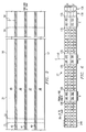
- Fig. 2 diagrammatically illustrates a magnetic tape usable in the Fig. 1 illustrated device and that incorporates a preferred form of the present invention.
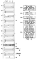
- Fig. 3 diagrammatically illustrates a serpentine track arrangement for the Fig. 2 illustrated tape.
- Fig. 4 diagrammatically illustrates a transducer employing the present invention that is indexed and servo-positioned with respect to a plurality of servo areas on a magnetic tape.
- Fig. 5 is a greatly enlarged showing of one servo track area with servo gap positioning for effecting the head indexing shown in Fig. 4.
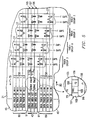
- Fig. 6 is an enlarged diagrammatic showing of a preferred head gap pattern for practicing the present invention.
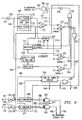
- Fig. 7 is a simplified block diagram showing of selecting head servo gaps for selecting position error signals (PES) for practicing the present invention.
- Fig. 8 is a simplified block diagram showing error detection and PES blocking based on PES excessive-error detection.
- Fig. 9 is a simplified logic-flow diagram illustrating an independent assessment of quality of a current head position using independent head position sensors shown in Fig. 4.
- a tape drive 10 is connected to other units 12.
- Other units 12 represent peripheral controllers, computers of all types, communication systems, local networks and the like.
- a tape cartridge 17 containing a single spool 20 of magnetic tape 21 is removably inserted into tape drive 10.
- Tape cartridge 17 shown in a play position operatively connects a spool motor and tachometer 22 to tape spool 20 for unreeling and reeling tape 21.
- Tape 21 is automatically threaded in a known manner past laterally-positionable multi-track multi-gap head 27 to machine reel 25. Data are transferred between tape 21 and other units 12 via data flow 28.
- Data flow 28 performs the usual formatting, error detecting and correcting, and other processing of information-bearing signals (data) found in magnetic tape recording apparatus.
- Motor and tachometer 26 rotate spool 25 in synchronism with spool 20, as is known.
- Lines 23 denote control and sensing signal transfer between motors 22 and 26 with tape device control 30.
- Control 30 includes the usual programmed control for controlling data flow 28 and communicating with other units 12.
- Cartridge present sensor 31 senses the cartridge 17 for informing control 30 that cartridge 17 has been loaded into tape drive 10
- Tape 21 includes triple longitudinally-extending laterally-spaced-apart redundant identically-constructed servo areas 40-42, which divide the tape 21 into a group of data track areas 45-48.
- a device to tape calibration area is disposed between dashed lines 50 and 52. This area contains signals (not described) that enable tape drive 10 to calibrate its operation to the particular characteristics of the loaded tape 21.
- the tape area between dashed lines 52 and 59 indicates tape 21 area available for recording as will become apparent. Dashed line 59 represents an end of the tape 21 recording area at the hub end of the tape.
- Numeral 58 denotes the four track groups 0-3 used in the constructed embodiment. Serial recording proceeds from track group 0 through track group 3, no limitation thereto intended. The first track group 0 is laterally displaced from longitudinal edges 56 and 57 respectively by tracks in track groups 3 and 1,2. Since track group 0 is a logical beginning of data recording, control information useful to either other units 12 or tape drive 10 may be first recorded in track group 0. Tape drive 10 has the usual load point controls for positioning magnetic tape and magnetic head 27 to first read the tracks in track group 0.
- Fig. 3 diagrammatically illustrates obtaining a maximal spacing between adjacent tracks in each track group 0-3.
- Numerals 81-89 respectively indicate track clusters 1-10 and numeral 89 indicates a plurality of track clusters in data track area 46.
- Each track cluster has one track from each track group.
- Laterally adjacent track clusters have tracks scanned in opposite scanning directions 79 and 80.
- Magnetic tape 21 moves in a direction to the track scanning direction by magnetic head 27.
- the "to hub” scanning direction is caused by magnetic tape 21 being reeled from cartridge spool 20 while the “from hub” scanning direction is caused by magnetic tape being reeled onto cartridge spool 20.
- Magnetic tape is scanned in a serpentine sequence.
- one serpentine scan also termed a track wrap, occurs.
- scan direction 79 one track in each of the odd numbered clusters are scanned while in scan direction 80 one track in each of the even numbered track clusters are scanned.
- the arrows in the respective track clusters 81-89 indicate the tracks.
- Each vertical number sequence "3 0 1 2" in each of the track clusters respectively indicate the track group to which the respective track belongs.
- the concurrently accessed tracks of each track group are spaced apart by seven intervening tracks. For example, tracks 1 and 9, as determined by the equations above, are laterally separated by tracks 2 through 8. For having four groups of tracks, such lateral spacing is maximum for all tracks and is the same for all successively numbered tracks in each track group.
- the tracks of track group 2 in the even numbered track clusters are not accessed concurrently to the track group 2 tracks in odd numbered clusters.
- the four data track areas 45-48 (Fig's 2 and 4) have a like number of tracks (each data track area having eight track clusters) such that the servo track areas 40-42 have a maximum lateral spacing.
- Such maximum lateral spacing is an optimum spacing for reducing errors caused by magnetic tape defects.
- a pair of unrecorded longitudinally-extending guard bands 91 (Fig. 3 and 5) separate the data track areas from each of the servo track areas 40-42.
- Fig. 4 shows indexing head 27 laterally of magnetic tape 21.
- Magnetic head 27 has three sets of servo gaps A, B and C (Fig. 6) that concurrently sense the respective servo track areas 40-42, respectively.
- the sensed servo signals are processed as later described with respect to Fig's 7 and 8 to generate a servo drive signal on line 100 for actuating servo 97 to move head 27 to follow the servo tracks.
- Numeral 98 indicates the physical connection of servo 97 to head 27.
- Also included in servo 97 is an electronic circuit (not shown) that initially indexes head 27 to position the servo gaps over the respective servo track areas 40-42.
- Independent position sensor 90 is physically interposed between head 27 (such as position mark mounted on a carriage for head 27 - -not shown) and an optical or magnetic sensor (not shown) in position sensor 90 detects and indicates relative position of head 27 with respect to a usual frame (not shown) of tape drive 10. Sensor 90 supplies a current independently sensed relative position of head 27 to the frame, hence to the lateral position of magnetic tape 21 as it is transported past head 27.
- step 262 actuates reference position register 95 to receive and store a current independent relative position of head 27.
- the stored independent position value is termed a reference position.
- step 264 performs the usual data recording (writing) and reading operations that require the described track group selection and track following.
- step 265 monitors the head 27 lateral position. During predetermined measurement periods, such as one each PES cycle (scanning one area 108 or 109 shown in Fig. 5), step 265 actuates current position register 92 to transfer its contents to previous position register 93, then to receive and store a new current position from sensor 90.
- step 266 actuates error detection circuit 94 to do an error evaluation that is independent of PES processing as shown in Fig's 7 and 8.
- a first evaluation comprises comparing the contents of registers 92 and 93 to detect any change in the lateral position of head 27.
- Circuit 94 has a suitable threshold against which the detected change in position is compared. If the change exceeds the threshold, then a signal on line 101 travels to the Fig. 8 illustrated OR circuit 239 for supplying a servo error condition signal on line 193. This signal stops all recording. Also, the position tolerances of servo track areas 40-42 and the lateral tape slewing during usual tape transport are priori information.
- a second threshold value in circuit 94 indicates the servo track area expected deviations from the reference positions between dashed lines 50-52 (Fig. 2) and from the tape slewing. Circuit 94 compares the current position value in register 92 with the second threshold. If the current position value is outside the priori tolerance, then an error signal is supplied over line 101 to OR circuit 239.
- the above operations are preferably program implemented in control 30 using usual programmed comparison and detection procedures.
- servo track areas 40-42 are identical.
- Servo track area 42 between data track areas 45 and 46 is detailed.
- a longitudinally-extending modulated servo area 107 is interleaved between tone areas 105 and 106.
- Area 107 has alternating sections 108 of frequency-F2 tone with sections 109 of null (all 0's signal in a data format, such as in a 1,7 d,k code) signal.
- F1 and F2 have a predetermined different frequency for effecting lateral position indication at the boundaries (servo tracks) 115 and 116 between the F1 and F2 frequency.
- the null sections 109 enable checking centering of an active servo gap scanning the respective servo tracks 115 and 116. The servo positioning action will be described with respect to Fig. 5 after the Fig. 6 illustrated head gap arrangement is next described.
- Magnetic head 27 has two portions F and H with interleaved write and read gaps.
- US patent 5,161,299 (patent '299) shows an multi-gap multi-track head that does not have servo gaps.
- the head used in this invention is an improvement over the magnetic head shown in said patent '299. All of the odd numbered write gaps W in section H write data in scanning direction 80 while the even-numbered write gaps W in section F write data in scanning direction 79.
- the read after write verification is respectively effected by the odd-numbered and even-numbered read gaps R in the scanning directions 79 and 80.
- read gaps R also read data from magnetic tape 21.
- Magnetic head 27 has 32 write gaps (16 in each head section) and 32 read gaps (16 in each head section). Therefore, magnetic head 27 concurrently reads or writes in 16 different tracks in a respective one of the track groups 0-3.
- the magnetic head 27 servo gaps are arranged into three sets, A, B and C, respectively for scanning servo track areas 42-40.
- Each head section F and H has two servo gaps in each of the sets A-C.
- the servo gaps are respectively identified by a three digit code, a first digit (F or H) indicates the head section, a second digit (A-C) indicates which of the three sets has the identified servo gap and a third digit (1 or 2) indicates which of the two servo gaps in the respective head section is identified.
- the data gaps (W and R) are arranged in four head lateral areas corresponding to the data track areas 45-48 as best seen in Fig. 6.
- the odd numbered write gaps respectively concurrently record in one track of the odd numbered track clusters. That is, gap W1 records data in track cluster 1 (one of the tracks 1-4).
- gap W3 records in track cluster 3 (one of the tracks 9-13), etc.
- even numbered write gaps record in even numbered track clusters.
- Head 27 is indexed to one of four positions for writing or reading from the tracks (respectively in track groups 0-3).
- Numeral 130 denotes the symmetrical lateral center of head 27 gap arrangement.
- Numeral 135 collectively indicates gap spacing for generating guard bands 91.
- Numeral 136 indicates gaps numbered 25-32 but not shown in Fig. 6.
- Servo gaps in gap set A illustrate the four-index positions. Since servo gaps HA1 and HA2 are used to position in scanning direction 79 and servo gaps FA1 and FA2 are identically used in scanning direction 80. The four head 27 index positions and two directions of relative head-to-tape motion, results in using each of the servo gaps twice as set forth below in Table I. TABLE I Servo gap usage Track Group Direction 79 Direction 80 Servo Track 0 HA2 FA2 115L 1 HA1 FA1 115U 2 HA1 FA1 115L 3 HA2 FA2 115U
- Head indexing uses electronic circuits of known design to initially position head 27 in one of the four servo positions.
- the centered servo gap senses the servo pattern to enable automatically switching from the open loop indexing to servo track following, all as known.
- Fig's 7 and 8 are a combination of electronic circuits and program implemented operations. That is, filters 165-167 can be conventional electronic filters that supply analog signals over lines 175 and 176 to amplitude comparators 170-172, respectively. In one embodiment, the output signals of filters 165-167 were digitized to digitally represent read back signal amplitudes. In this one embodiment averaging circuit 191 and gates 180-182 are program implemented. It is well within one of ordinary skill in this art to make such design choices for implementing the present invention.
- Fig. 7 First described for Fig. 7 is servo gap selection for effecting track following.
- Each servo gap set A, B and C has four servo gaps as described with respect to Fig's 5 and 6.
- Fig. 5 illustrates which of the servo gaps in each set are selected for the respective concurrent track groups as indicated by control 30 over line 151 to select servo gap circuit 150. While the tracks in any of the concurrent track groups are being scanned while tape is being reeled from cartridge spool 20 to machine spool 15 then the servo gaps are always in head section F. While scanning tape in an opposite direction while tape is being reeled from machine reel 25 to cartridge reel 20, the servo gaps in head section H are used.
- select servo gaps circuit (can be partially program implemented) 150 responds to the group select signal on line 151 and the tape direction signal on line 152 to select one servo gap from each servo gap set A, B and C, respectively over lines 155-157, for supplying three independently read servo signals respectively over lines 160-162 to filter circuits 165-167.
- Filter circuits 165-167 each separately filter the F1 and F2 signals read from the respective servo track areas 42-40.
- Lines 175 respectively carry the F1 filtered signals while lines 176 respectively carry the F2 filtered signals.
- Amplitude comparators 170-172 respectively amplitude compare, such as by either analog or digital subtraction of one of the signal amplitudes from another signal amplitude to supply respective differential servo position error indicating signals over the respective lines 173 to gates 180-182.
- Gates 180-182 respond to position error detection circuit 184 to pass the respective position error signals while circuit 184 indicates respectively over lines 187-185 satisfactory signal quality has occurred while reading the servo signals from tape 21 respective servo track areas.
- the gates 180-182 passed servo position error signals all proceed over respective lines 190 to averaging circuit 191 For writing data onto tape 21 two of the three position error signals must be valid.
- position error detection circuit 184 supplies a servo error signal over line 193 that effects aborting writing data.
- one of the servo position error signals may be used for a successful read.
- Other read controls may be implemented as well but are not described herein.
- Acquisition of track following for any of the four concurrent track groups includes open-loop indexing or stepping magnetic head 27 under control of index control 145.
- Control 30 supplies lateral position information over cable (can be a program path) 144 to control 145.
- Control 145 supplies an appropriate control signal over line 100 to actuate the Fig. 4 illustrated head 27 positioning servo/indexer 97. As the active servo gaps begin scanning the respective servo track areas 40-42 position error signals are being generated.
- Index control 145 responds to position error detection circuit 184 supplying an indication over line 146 that servo position error signals are being generated and to a control 145 internal indication (not shown) that the indexing operation has caused the active servo gap to reach the desired servo track 115U or 115L to supply a gate enabling signal (can be a program signal) over line 147 to actuate gates 180-182 to pass the respective lines 173 signals conditioned on the value of the respective signals on lines 187-185.
- a gate enabling signal can be a program signal
- Fig. 8 illustrates in simplified form the operation of circuit 184.
- Numerals 201 and 200 represent reading the servo track area 42 (via an active gap of the A servo gap set) arid amplification of the sensed servo signal.
- Filters 165 includes an F1 signal passing filter 205 to supply F1 over line 175 while F2 signal passing filter 206 to supply F2 over line 176.
- the amplitudes of the F1 and F2 signals on lines 175 and 176 indicate servo position error.
- Amplitude comparator 170 generates the position error signal "F1-F2" traveling over line 173 to AND circuit or gate 180.
- the line 187 control signal opens gate 180 when no error conditions in the A circuit portion of circuit 184 indicate poor sensed signal quality or an unintended off-track condition. Three such errors are described. Error 1 occurs if the F1-F2 signal has too high an amplitude for indicating that the servo gap is favoring sensing the F1 portion 105 or 106 (Fig. 5). Amplitude comparator 217 compares F1-F2 with amplitude threshold T1. Error 1 is indicated if F1 > F2 more than T1. F1 can also be compared to a threshold amplitude during the null periods when the servo gap is scanning an F1 area and a null area 109.
- Comparator 217 is activated by detector 211 responding to the transition from an F2 area 108 to a null area 109 to supply a timing signal over line 218 for actuating comparator 217 to output a new value and hold it until the next F1 to null transition.
- Error 2 indicates that F1 amplitude value changes beyond a predetermined maximum value during the periods that an area F2 is being scanned as indicated by threshold signal T2.
- the F1 signal amplitude value is captured and held in hold circuit 220 (determination of error 2 is program implemented in one embodiment).
- Line 175 connects to one input of hold circuit 220.
- Hold circuit 220 is enabled to receive and store the F1 signal while an F2 area 108 is being scanned.
- Detector 211 detects and indicates an F2 signal and supplies an actuating signal over line 212 to hold circuit to receive F1 signal.
- Detector 211 detects and indicates on line 218 each transition from an F2 area 108 to a null area 109 for actuating hold circuit 220 to supply the captured F1 signal over line 221 to error 2 detecting amplitude comparator 225.
- the line 212 F2 scan indicating signal is removed for disabling circuit 220 from receiving the F2 signal.
- Comparator 225 compares the line 221 captured F1 signal with threshold T2. When the captured F1 signal has a greater amplitude than T2, an unintended servo offset is indicated. Therefore, comparator 225 then emits an error 2 signal over line 226.
- Error 3 signal indicates excessive noise is being sensed from the servo track area being scanned.
- the line 160 signal enters blocking or comb filter 230 for blocking the F1, F2 and any null signal (such as all 0's indicated d,k coded signal) for passing noise signals to amplitude detector 231.
- Detector 231 supplies a noise amplitude indicating signal to error 3 amplitude comparator 233.
- Comparator 233 compares the detector 231 supplied signal with a third amplitude threshold T3. If the noise indicating signal exceeds T3, then comparator 233 supplies an error 3 indicating signal over line 234.
- the line 187 AND gate conditioning signal is generated by OR circuit 215 supplying an actuating signal to invertor 216.
- invertor 216 actuates AND gate 180 to pass the line 173 F1-F2 servo position error signal.
- none of the error comparators 217, 225 and 233 are not detecting an error condition and the F2 scan signal on line 212 is active, then there is an inactive output signal from OR circuit 215 for actuating AND gate 180. Any one of the error comparators 217, 225 or 233 supplying an error signal or the F2 scan signal on line 212 is inactive, then AND gate 180 closes to block the line 173 signal from passing to averaging circuit 191.
- a circuit in circuit 184 that processes sensed servo signals from the A set of servo gaps.
- B circuit 240 and C circuit 241 respectively operate as described for the A circuit.
- AND gates 181 and 182 are controlled by B and C circuits, respectively, as described for the A circuit.
- the sensed servo signal inputs to the B and C circuits are respectively carried over lines 161 and 162 through circuits 166 and 167 (filters) to lines collectively indicated by numerals 175,176 in Fig. 8.
- the line 193 servo turn off signal is generated by two of three circuit 238 responding to two of the three circuits A, B and C indicating one of three errors 1, 2 or 3.
- OR gate 237 receives the output signals from error comparators 217, 225 and 233. Any one of the lines 219, 226 or 234 carrying an error indicating signal passes through OR gate 237 to supply an A circuit error indicating signal to circuit 238.
- B and C circuits respectively supply B and C circuit error indicating signals over lines 243 and 244 to two-of-three circuit 238.
- Circuit 238 consists of logic program elements using known designs to indicate on line 193 through OR circuit 239 that two of the three servo signals are in an error condition. Remember, that two such error conditions cause any data writing to be aborted.
- Line 146 carries a signal that is the inverse of the line 193 signal for indicating that at least two of the three sensed servo signals are valid.
- signal used above with respect to error determination, servo control and the like refers to either program implement (as noted) or electrical signals (not noted but determinable from the context, i.e. sensing signals on a tape, etc).
- program implement as noted
- electrical signals not noted but determinable from the context, i.e. sensing signals on a tape, etc.
- the mix of program implementation and electric circuit implementation is deemed to be a matter of design choice for practicing the present invention.
Landscapes
- Engineering & Computer Science (AREA)
- Computer Hardware Design (AREA)
- Adjustment Of The Magnetic Head Position Track Following On Tapes (AREA)
Applications Claiming Priority (2)
| Application Number | Priority Date | Filing Date | Title |
|---|---|---|---|
| US08/075,624 US5574602A (en) | 1993-06-14 | 1993-06-14 | Processing servo signals concurrently read from plural spaced-apart servo areas for a magnetic tape having serpentine data track scanning |
| US75624 | 1993-06-14 |
Publications (2)
| Publication Number | Publication Date |
|---|---|
| EP0630000A2 true EP0630000A2 (fr) | 1994-12-21 |
| EP0630000A3 EP0630000A3 (fr) | 1995-02-22 |
Family
ID=22126985
Family Applications (1)
| Application Number | Title | Priority Date | Filing Date |
|---|---|---|---|
| EP94108206A Withdrawn EP0630000A3 (fr) | 1993-06-14 | 1994-05-28 | Procédé et appareil de traitement de signaux d'asservissement lues simultanément à partir de zones d'asservissement séparées sur une bande magnétique. |
Country Status (4)
| Country | Link |
|---|---|
| US (1) | US5574602A (fr) |
| EP (1) | EP0630000A3 (fr) |
| JP (1) | JPH0757229A (fr) |
| BR (1) | BR9402178A (fr) |
Cited By (5)
| Publication number | Priority date | Publication date | Assignee | Title |
|---|---|---|---|---|
| WO1997021213A1 (fr) * | 1995-12-07 | 1997-06-12 | Philips Electronics N.V. | Positionnement d'une tete par rapport a plusieurs pistes |
| EP0883110A2 (fr) * | 1997-06-05 | 1998-12-09 | Hewlett-Packard Company | Système d'asservissement redondant |
| US5886845A (en) * | 1996-08-13 | 1999-03-23 | Imation Corp. | Tape pack shift detection and retensioning methods and drive apparatus regarding same |
| US5917671A (en) * | 1996-03-14 | 1999-06-29 | Deutsche Thomson-Brandt Gmbh | Recording method and information medium for a plurality of longitudinal track bundles enabling tracking during recording and/or playback of track bundles |
| WO2000019422A1 (fr) * | 1998-09-29 | 2000-04-06 | Storage Technology Corporation | Procede ameliore de fixation d'une bande a une cartouche de bobine de bande |
Families Citing this family (32)
| Publication number | Priority date | Publication date | Assignee | Title |
|---|---|---|---|---|
| US5872672A (en) * | 1996-02-16 | 1999-02-16 | International Business Machines Corporation | System and method for monitoring and analyzing tape servo performance |
| US5828514A (en) * | 1996-02-16 | 1998-10-27 | International Business Machines Corporation | Servo error detection in a noisy environment |
| KR100212984B1 (ko) * | 1996-06-05 | 1999-08-02 | 윤종용 | 위치에러신호를 정확히 측정하기 위한 방법 |
| US5946156A (en) * | 1997-03-04 | 1999-08-31 | Imation Corp. | Tape servo system and methods, write/read heads, and servo track configurations regarding same |
| US6172837B1 (en) * | 1998-03-23 | 2001-01-09 | Hewlett-Packard Company | Postponable servo code selection |
| US6330123B1 (en) | 1999-05-28 | 2001-12-11 | Imation Corp. | Head assembly having a single pass servo writer |
| US6525898B1 (en) | 1999-08-03 | 2003-02-25 | International Business Machines Corporation | Detection of indexed servo positions displaced from servo track edges |
| US6462899B1 (en) * | 2000-01-04 | 2002-10-08 | International Business Machines Corporation | Initialization and calibration of a recording system track following servo |
| JP2001250346A (ja) | 2000-03-06 | 2001-09-14 | Fujitsu Ltd | 磁気テープ装置 |
| US6563659B1 (en) | 2000-03-08 | 2003-05-13 | Hewlett-Packard Development Company, L.P. | Method and apparatus for servo code based tape tension measurement |
| US6661600B1 (en) | 2000-11-02 | 2003-12-09 | International Business Machines Corporation | Calibration of servo index positions of a magnetic tape employing second order curve fitting |
| US6839196B2 (en) * | 2001-05-24 | 2005-01-04 | Quantum Corporation | Magnetic track following servo algorithm using signal quality |
| US6813112B2 (en) * | 2001-09-06 | 2004-11-02 | International Business Machines Corporation | Method, apparatus and software for tape drive mechanical fault detection |
| US6950269B1 (en) * | 2002-01-18 | 2005-09-27 | Imation Corp. | System and methods for using servopositioning signals |
| US6831805B2 (en) | 2002-06-27 | 2004-12-14 | International Business Machines Corporation | Apparatus and method to read and/or write information to a magnetic tape medium |
| US7299146B2 (en) * | 2002-06-27 | 2007-11-20 | International Business Machines Corporation | Apparatus and method to calibrate a system having an input signal and an output signal |
| US6831806B2 (en) * | 2002-06-27 | 2004-12-14 | International Business Machines Corporation | Apparatus and method to calibrate a servo sensor |
| US6833973B2 (en) * | 2002-06-27 | 2004-12-21 | International Business Machines Corporation | Apparatus and method to calibrate a servo sensor |
| US6865052B2 (en) * | 2002-06-27 | 2005-03-08 | International Business Machines Corporation | Apparatus and method to calibrate servo sensors in a noisy environment |
| US6839197B2 (en) * | 2002-06-27 | 2005-01-04 | International Business Machines Corporation | Apparatus and method to calibrate one or more transducers in a noisy environment |
| JP2004185765A (ja) * | 2002-12-06 | 2004-07-02 | Fuji Photo Film Co Ltd | 磁気テープドライブの検査方法及びその検査方法に用いられる検査用テープの製造方法 |
| US7099102B2 (en) * | 2003-10-20 | 2006-08-29 | Quantum Corporation | Multiple format magnetic storage media drive |
| US7265935B2 (en) * | 2004-12-15 | 2007-09-04 | International Business Machines Corporation | Velocity adaptive compensator for a synchronous sampling time-based servo system |
| US7474488B2 (en) * | 2005-08-30 | 2009-01-06 | International Business Machines Corporation | Magnetic head, tape drive system, and method |
| US7253986B2 (en) * | 2005-08-30 | 2007-08-07 | International Business Machines Corporation | System and method for deconvolution of multiple data tracks |
| US7760465B2 (en) * | 2005-10-25 | 2010-07-20 | International Business Machines Corporation | Magnetic head having selectively defined reader gap thicknesses |
| US7436615B2 (en) * | 2005-12-08 | 2008-10-14 | International Business Machines Corporation | Using a measured error to determine coefficients to provide to an equalizer to use to equalize an input signal |
| US20080068752A1 (en) * | 2006-09-19 | 2008-03-20 | International Business Machines Corporation | Planar Bidirectional Tape Head With Planar Read And Write Elements |
| US7978429B2 (en) * | 2006-09-19 | 2011-07-12 | International Business Machines Corporation | Low track pitch write module and bidirectional tape head |
| US20080068750A1 (en) * | 2006-09-19 | 2008-03-20 | International Business Machines Corporation | Planar Write Module And Hybrid Planar Write-Vertical Read Bidirectional Tape Head |
| US20120212846A1 (en) * | 2011-02-23 | 2012-08-23 | Oracle International Corporation | Method of Calibrating Data Readers Relative to Servo Readers |
| JP6628762B2 (ja) | 2017-04-28 | 2020-01-15 | 富士フイルム株式会社 | 記録制御装置及び記録制御方法 |
Citations (4)
| Publication number | Priority date | Publication date | Assignee | Title |
|---|---|---|---|---|
| EP0443810A2 (fr) * | 1990-02-20 | 1991-08-28 | Sharp Kabushiki Kaisha | Dispositif de contrôle de pistage pour un appareil d'enregistrement/reproduction magnétique |
| EP0508366A2 (fr) * | 1991-04-12 | 1992-10-14 | Sharp Kabushiki Kaisha | Dispositif pour mettre en position une tête magnétique |
| DE4216896A1 (de) * | 1991-05-22 | 1992-11-26 | Sharp Kk | Magnetisches aufzeichnungs- und wiedergabegeraet mit positionseinstellbarem kopf |
| EP0517531A2 (fr) * | 1991-06-07 | 1992-12-09 | Minnesota Mining And Manufacturing Company | Tête multi-piste d'enregistrement de données d'asservissement, support correspondant ayant une piste d'asservissement pré-enregistrée, et système de positionnement de tête asservie |
Family Cites Families (26)
| Publication number | Priority date | Publication date | Assignee | Title |
|---|---|---|---|---|
| US4048660A (en) * | 1975-12-23 | 1977-09-13 | International Business Machines Corporation | Record track following and seeking |
| JPS5448210A (en) * | 1977-09-26 | 1979-04-16 | Sony Corp | Automatic tracking system |
| NL7907219A (nl) * | 1979-09-28 | 1981-03-31 | Philips Nv | Apparaat voor het opnemen en/of weergeven van op een magneetband in een aantal parallele, longitudinale sporen opgenomen magnetische signalen. |
| US4472750A (en) * | 1981-07-02 | 1984-09-18 | Irwin Magnetic Systems, Inc. | Data record with pre-recorded transducer positioning signals, and system for utilizing same |
| US4409628A (en) * | 1981-11-16 | 1983-10-11 | Honeywell, Inc. | Tape transport speed control using a playback data derived clock signal |
| US4558380A (en) * | 1983-05-11 | 1985-12-10 | Pertec Peripherals Corporation | Digital tape transport for selectively recording in either a parallel or serial mode |
| DE3521437A1 (de) * | 1983-11-29 | 1986-12-18 | Sharp K.K., Osaka | Mehrspur-magnetbandgeraet und verfahren zur spureinstellung seiner wiedergabekoepfe |
| JPS60124020A (ja) * | 1983-12-08 | 1985-07-02 | Fujitsu Ltd | デ−タ記憶装置のヘッド位置検出方式 |
| JPS60125916A (ja) * | 1983-12-12 | 1985-07-05 | Toshiba Corp | ヘッド位置制御装置 |
| DE3347632A1 (de) * | 1983-12-30 | 1985-07-11 | Tandberg Data A/S, Oslo | Anordnung zum positionieren eines wandlers auf mindestens einer spur eines bandfoermigen aufzeichnungstraegers |
| US4760475A (en) * | 1986-11-13 | 1988-07-26 | Ampex Corporation | Home track position acquisition system and method |
| EP0275078B1 (fr) * | 1987-01-13 | 1995-04-05 | Nec Corporation | Système de contrôle de suivi de piste par unité de disque magnétique |
| US4719397A (en) * | 1987-04-06 | 1988-01-12 | Cincinnati Milacron Inc. | Method and apparatus for tape dispensing servo tracking control |
| JPH01184675A (ja) * | 1988-01-11 | 1989-07-24 | Nec Corp | 磁気記録装置およびトラックアクセス方式 |
| US4979051A (en) * | 1988-03-22 | 1990-12-18 | Eggebeen James A | Bimodal multi-track magnetic head |
| US4977472A (en) * | 1988-03-28 | 1990-12-11 | Seagate Technology, Inc. | Servo address system |
| US5008765A (en) * | 1989-01-17 | 1991-04-16 | Minnesota Mining And Manufacturing Company | Method and apparatus for reading or writing on tape using a servo positioned multiple channel head |
| US5055951A (en) * | 1989-03-10 | 1991-10-08 | Irwin Magnetic Systems, Inc. | Method and apparatus for servo-positioning movable transducer heads |
| US5196969A (en) * | 1989-03-31 | 1993-03-23 | Sharp Kabushiki Kaisha | Head positioning system for serpentine magnetic recording/reproducing system |
| US5121270A (en) * | 1989-09-19 | 1992-06-09 | Alcudia Ezra R | Multitransducer head positioning servo for use in a bi-directional magnetic tape system |
| US5231550A (en) * | 1990-03-12 | 1993-07-27 | Fujitsu Limited | Track access control system preventing unintentional delay in movement of head in non-adjusted disc device |
| JP2600007B2 (ja) * | 1990-04-03 | 1997-04-16 | 三菱電機株式会社 | 磁気記録再生方法 |
| US5161299A (en) * | 1990-12-26 | 1992-11-10 | International Business Machines Corporation | Method of making a magnetic hybrid interleaved head |
| JPH04321917A (ja) * | 1991-04-19 | 1992-11-11 | Casio Comput Co Ltd | トラッキング制御装置 |
| JP2784100B2 (ja) * | 1991-05-22 | 1998-08-06 | シャープ株式会社 | 磁気記録再生装置 |
| US5229895A (en) * | 1991-06-07 | 1993-07-20 | Minnesota Mining And Manufacturing Company | Multi-track servo recording head assembly |
-
1993
- 1993-06-14 US US08/075,624 patent/US5574602A/en not_active Expired - Lifetime
-
1994
- 1994-05-28 EP EP94108206A patent/EP0630000A3/fr not_active Withdrawn
- 1994-06-06 BR BR9402178A patent/BR9402178A/pt active Search and Examination
- 1994-06-10 JP JP6129088A patent/JPH0757229A/ja active Pending
Patent Citations (4)
| Publication number | Priority date | Publication date | Assignee | Title |
|---|---|---|---|---|
| EP0443810A2 (fr) * | 1990-02-20 | 1991-08-28 | Sharp Kabushiki Kaisha | Dispositif de contrôle de pistage pour un appareil d'enregistrement/reproduction magnétique |
| EP0508366A2 (fr) * | 1991-04-12 | 1992-10-14 | Sharp Kabushiki Kaisha | Dispositif pour mettre en position une tête magnétique |
| DE4216896A1 (de) * | 1991-05-22 | 1992-11-26 | Sharp Kk | Magnetisches aufzeichnungs- und wiedergabegeraet mit positionseinstellbarem kopf |
| EP0517531A2 (fr) * | 1991-06-07 | 1992-12-09 | Minnesota Mining And Manufacturing Company | Tête multi-piste d'enregistrement de données d'asservissement, support correspondant ayant une piste d'asservissement pré-enregistrée, et système de positionnement de tête asservie |
Cited By (9)
| Publication number | Priority date | Publication date | Assignee | Title |
|---|---|---|---|---|
| WO1997021213A1 (fr) * | 1995-12-07 | 1997-06-12 | Philips Electronics N.V. | Positionnement d'une tete par rapport a plusieurs pistes |
| US5805372A (en) * | 1995-12-07 | 1998-09-08 | U.S. Philip Corporation | Positioning of a head relative to a plurality of tracks |
| US5917671A (en) * | 1996-03-14 | 1999-06-29 | Deutsche Thomson-Brandt Gmbh | Recording method and information medium for a plurality of longitudinal track bundles enabling tracking during recording and/or playback of track bundles |
| SG97752A1 (en) * | 1996-03-14 | 2003-08-20 | Thomson Brandt Gmbh | Recording method and information medium for a plurality of longitudinal track bundles enabling tracking during recording and/or playback of track bundles |
| US5886845A (en) * | 1996-08-13 | 1999-03-23 | Imation Corp. | Tape pack shift detection and retensioning methods and drive apparatus regarding same |
| EP0883110A2 (fr) * | 1997-06-05 | 1998-12-09 | Hewlett-Packard Company | Système d'asservissement redondant |
| EP0883110A3 (fr) * | 1997-06-05 | 2000-12-20 | Hewlett-Packard Company | Système d'asservissement redondant |
| WO2000019422A1 (fr) * | 1998-09-29 | 2000-04-06 | Storage Technology Corporation | Procede ameliore de fixation d'une bande a une cartouche de bobine de bande |
| US6322015B1 (en) | 1998-09-29 | 2001-11-27 | Storage Technology Corporation | Method of tape attachment to a tape cartridge reel |
Also Published As
| Publication number | Publication date |
|---|---|
| US5574602A (en) | 1996-11-12 |
| BR9402178A (pt) | 1995-10-03 |
| JPH0757229A (ja) | 1995-03-03 |
| EP0630000A3 (fr) | 1995-02-22 |
Similar Documents
| Publication | Publication Date | Title |
|---|---|---|
| US5574602A (en) | Processing servo signals concurrently read from plural spaced-apart servo areas for a magnetic tape having serpentine data track scanning | |
| EP0629999B1 (fr) | Bande magnétique avec plusieurs zones d'asservissement séparées, entrelacées avec les zones de piste de données | |
| EP0883110B1 (fr) | Système d'asservissement redondant | |
| US5452152A (en) | Tracking control on longitudinal azimuth tracks using an auxiliary read head | |
| US5448430A (en) | Track following servo demodulation | |
| US5629813A (en) | Initialization and calibration of magnetic tape having multiple servo areas | |
| EP0500760B1 (fr) | Poursuite asservie pour enregistreur a balayage helicoidal | |
| US5394280A (en) | Detecting a servo error on a magnetic tape and identifying extent and location of the detected servo error by linked control marks | |
| EP0777901B1 (fr) | Conformation d'une piste de donnees comprenant des secteurs de commande incorpores correspondant a la structure de la tete magnetoresistive d'une unite de disque | |
| US6023389A (en) | Method and apparatus for writing servo bursts with compensation for erase bands in a direct access storage device | |
| US5191491A (en) | Method and apparatus for reading distorted helical stripes | |
| US4052741A (en) | Track seeking and following | |
| US5828514A (en) | Servo error detection in a noisy environment | |
| US20030016465A1 (en) | Method and apparatus for providing linear position (LPOS) estimations | |
| US6172837B1 (en) | Postponable servo code selection | |
| US4816938A (en) | Process for determining data disk track centers | |
| WO1999050837A1 (fr) | Structure de positionneur a bande magnetique avec identification de piste | |
| EP0447460B1 (fr) | Systeme a double piste de reference | |
| US6798608B2 (en) | Active detection and acquisition of a servo track subject to lateral motion | |
| KR100261394B1 (ko) | 자기 테이프 기록 재생 장치 | |
| EP0590226B1 (fr) | Unité de mémoire à bande magnétique avec possibilité améliorée de lire des données en utilisant un groupe d'éléments multiples de lecture | |
| US20040212915A1 (en) | Tape drive servo operation by use of servo pattern width measurements | |
| EP0940812B1 (fr) | Encodage de position longitudinale absolue dans des systèmes de bande linéaire | |
| WO1994012975A1 (fr) | Procede et dispositif permettant d'identifier les pistes d'une bande | |
| US5416642A (en) | Dust-immune method and apparatus for gain control of a read amplifier in a magnetic tape transport |
Legal Events
| Date | Code | Title | Description |
|---|---|---|---|
| PUAI | Public reference made under article 153(3) epc to a published international application that has entered the european phase |
Free format text: ORIGINAL CODE: 0009012 |
|
| AK | Designated contracting states |
Kind code of ref document: A2 Designated state(s): DE FR GB |
|
| PUAL | Search report despatched |
Free format text: ORIGINAL CODE: 0009013 |
|
| AK | Designated contracting states |
Kind code of ref document: A3 Designated state(s): DE FR GB |
|
| 17P | Request for examination filed |
Effective date: 19950425 |
|
| GRAG | Despatch of communication of intention to grant |
Free format text: ORIGINAL CODE: EPIDOS AGRA |
|
| 17Q | First examination report despatched |
Effective date: 19971007 |
|
| GRAG | Despatch of communication of intention to grant |
Free format text: ORIGINAL CODE: EPIDOS AGRA |
|
| GRAH | Despatch of communication of intention to grant a patent |
Free format text: ORIGINAL CODE: EPIDOS IGRA |
|
| STAA | Information on the status of an ep patent application or granted ep patent |
Free format text: STATUS: THE APPLICATION IS DEEMED TO BE WITHDRAWN |
|
| 18D | Application deemed to be withdrawn |
Effective date: 19980423 |