EP0628111B1 - Collapsible barrier - Google Patents
Collapsible barrier Download PDFInfo
- Publication number
- EP0628111B1 EP0628111B1 EP94902012A EP94902012A EP0628111B1 EP 0628111 B1 EP0628111 B1 EP 0628111B1 EP 94902012 A EP94902012 A EP 94902012A EP 94902012 A EP94902012 A EP 94902012A EP 0628111 B1 EP0628111 B1 EP 0628111B1
- Authority
- EP
- European Patent Office
- Prior art keywords
- lower rail
- articulations
- barrier according
- barrier
- rod
- Prior art date
- Legal status (The legal status is an assumption and is not a legal conclusion. Google has not performed a legal analysis and makes no representation as to the accuracy of the status listed.)
- Expired - Lifetime
Links
Images


Classifications
-
- E—FIXED CONSTRUCTIONS
- E04—BUILDING
- E04H—BUILDINGS OR LIKE STRUCTURES FOR PARTICULAR PURPOSES; SWIMMING OR SPLASH BATHS OR POOLS; MASTS; FENCING; TENTS OR CANOPIES, IN GENERAL
- E04H5/00—Buildings or groups of buildings for industrial or agricultural purposes
- E04H5/02—Buildings or groups of buildings for industrial purposes, e.g. for power-plants or factories
- E04H5/06—Pits or building structures for inspection or services
-
- E—FIXED CONSTRUCTIONS
- E01—CONSTRUCTION OF ROADS, RAILWAYS, OR BRIDGES
- E01F—ADDITIONAL WORK, SUCH AS EQUIPPING ROADS OR THE CONSTRUCTION OF PLATFORMS, HELICOPTER LANDING STAGES, SIGNS, SNOW FENCES, OR THE LIKE
- E01F13/00—Arrangements for obstructing or restricting traffic, e.g. gates, barricades ; Preventing passage of vehicles of selected category or dimensions
- E01F13/04—Arrangements for obstructing or restricting traffic, e.g. gates, barricades ; Preventing passage of vehicles of selected category or dimensions movable to allow or prevent passage
- E01F13/044—Arrangements for obstructing or restricting traffic, e.g. gates, barricades ; Preventing passage of vehicles of selected category or dimensions movable to allow or prevent passage the barrier being formed by obstructing members situated on, flush with, or below the traffic surface, e.g. with inflatable members on the surface
-
- E—FIXED CONSTRUCTIONS
- E01—CONSTRUCTION OF ROADS, RAILWAYS, OR BRIDGES
- E01F—ADDITIONAL WORK, SUCH AS EQUIPPING ROADS OR THE CONSTRUCTION OF PLATFORMS, HELICOPTER LANDING STAGES, SIGNS, SNOW FENCES, OR THE LIKE
- E01F13/00—Arrangements for obstructing or restricting traffic, e.g. gates, barricades ; Preventing passage of vehicles of selected category or dimensions
- E01F13/04—Arrangements for obstructing or restricting traffic, e.g. gates, barricades ; Preventing passage of vehicles of selected category or dimensions movable to allow or prevent passage
- E01F13/048—Arrangements for obstructing or restricting traffic, e.g. gates, barricades ; Preventing passage of vehicles of selected category or dimensions movable to allow or prevent passage with obstructing members moving in a translatory motion, e.g. vertical lift barriers, sliding gates
-
- E—FIXED CONSTRUCTIONS
- E04—BUILDING
- E04G—SCAFFOLDING; FORMS; SHUTTERING; BUILDING IMPLEMENTS OR AIDS, OR THEIR USE; HANDLING BUILDING MATERIALS ON THE SITE; REPAIRING, BREAKING-UP OR OTHER WORK ON EXISTING BUILDINGS
- E04G21/00—Preparing, conveying, or working-up building materials or building elements in situ; Other devices or measures for constructional work
- E04G21/32—Safety or protective measures for persons during the construction of buildings
- E04G21/3204—Safety or protective measures for persons during the construction of buildings against falling down
- E04G21/3223—Means supported by building floors or flat roofs, e.g. safety railings
Definitions
- the invention relates to an extendable barrier, in particular intended to constitute a railing or a barrier, or even a signaling barrier.
- the present invention is indeed more particularly, but not exclusively, intended to protect pits, trenches, or the like, against accidental falls of passers-by or workers, and in general, to temporarily protect, permanent excavations , such as garage pits.
- the invention also make it possible to equip a platform, a terrace, a loading dock, or the like, but it also makes it possible to provide a temporary barrier for parking, pedestrian street, work areas, etc. or constitute a simple support barrier for signaling.
- a garage pit railing for example, has a heald, a sill and a baseboard.
- Such a guardrail must be able to be installed and uninstalled easily since it must not hinder the use of the pit.
- One of the drawbacks of the known devices is the need to provide a housing for the folded railing which constitutes a grip on the pit and / or requires earthworks.
- the barrier according to the invention makes it possible inter alia to avoid this drawback.
- the invention indeed provides an extendable barrier comprising at least one heald and one sub-heald, but which is remarkable in that the heald is supported by at least two mechanical diamonds separated from one another and each formed of four arms hinged together at their ends, in that the heald is fixed to one of the articulations of each rhombus, called heald articulation, the diametrically opposite articulation, called ground articulation, being intended to be fixed to the ground or on an element to be fixed or placed on the ground, while the sub-rail is constituted by at least one rod parallel to the rail which crosses the two other joints of each rhombus, called under-hinge joints, or is crossed by them, and that at least one blocking system is provided for blocking the barrier in at least one position of use.
- the blocking system comprises on at least one of the sub-hinge joints for each diamond, a threaded ring, intended to come into engagement with a threaded part of the sub-smooth rod.
- a rotational drive means is further provided to be engaged with the sub-rail rod so that the rotation of the latter causes the spacing, or the approximation, of the sub articulations. -smooth and vice versa the approximation or spacing of the heald and ground joints.
- the sub-arm rod has for each rhombus a threaded part for only one of the sub-hinge joints of said rhombus and a smooth part for the other sub-hinge articulation, the latter comprising a ring wherein said sub-arm rod can slide freely.
- the locking system comprises for each rhombus and on at least one of the sub-hinge joints, a pawl intended to come into engagement with at least one notch formed on the rod sub-arm, which is made rotatable to be able to disengage from the pawl by simple rotation.
- At least one counterweight is provided to hold the sub-arm rod in a position in which the notches with which it is provided, are turned towards the pawls.
- Such a barrier can also be constituted by several elementary barriers connected together by means which subject the sub-rails to rotation as desired, while a means for locking in rotation can be provided on at least one of said elementary barriers.
- the blocking system includes, for some at least of the diamonds, a double-acting cylinder whose rod acts on one of the arms of said diamond, while the sub-arm joints are slidably mounted in the sub-arm so that actuation of the actuator causes the sub-arm articulations to move apart, or reciprocally, and vice versa, the approximation or the spacing of the heald and floor joints.
- the cylinder of the jack is positioned substantially at ground level, parallel to the sub-beam and to the beam, while the rod of said cylinder is articulated by at least one link to one of the arms neighboring the ground joint of said rhombus.
- the end of the cylinder rod can, for example, be articulated to the link by means of at least one roller.
- one of the two sub-hinge joints of at least some of the diamonds are connected together by a connecting bar.
- at least some of the sub-hinge joints are stressed by a compression spring acting in particular as a damping means on the descent.
- the sub-rail rod has several sections connected to each other by articulated connections thus making it possible to constitute a barrier in a broken line.
- the floor joint is, for example, fixed to a base forming at least one plinth, said base being intended to be fixed or to rest on the ground.
- the base can have the shape of an inverted T, but also the shape of a U.
- the base can also be intended to be placed in an excavation provided for this purpose.
- the base is, for example, framed on either side of its length by elements forming a ramp and it is articulated to at least one of said elements which rests on the ground of such so that the other element is raised when the barrier is forced towards the articulated element.
- the ends of the heddle can be slidably mounted in two lateral uprights, means which can also be provided in at least one of the uprights to activate the barrier by acting on the arm.
- a barrier according to the invention as shown in Figures 1 to 6, comprises a base 1 intended to be fixed or placed on the ground, or on any element integral with the latter, and a heddle 2 in the form of a bar (identical parts from one embodiment to another having the same references).
- the rail 2 is movably attached to the base 1, by means of articulated arms forming diamonds such as diamonds 3 and 3 '.
- each rhombus 3, 3 ' is made up of four arms hinged together.
- the base 1 and the rail 2 in fact comprise parts respectively 4 and 5 on which the corresponding ends of two arms of each rhombus are articulated, and this is why the parts 4 and 5 will be referred to hereinafter as joints of ground and smooth.
- the other two joints 6, 6 'and 7, 7' are said to be sub-smooth for the reasons which will be understood below.
- the sub-hinge joints 6, 7 comprise for one 6, a threaded ring 8 and for the other 7, a smooth ring 9.
- the rings 8 and 9 of the joints 6 and 7 are crossed by the sub-rail formed by at least one bar or rod 10.
- the rod 10 here has threaded parts 10a and smooth parts 10b.
- the threaded parts 10a are intended to cooperate with the threaded rings 8 and the smooth parts 10b are intended to pass freely through the rings 9.
- a rotation of the sub-rail rod 10 makes it possible, by screwing and unscrewing, to bring the joints 6 and 7 closer or apart and at the same time of course respectively to move the joints 4 and 5 and therefore raise or lower the heald 2 and the rod 10 of the sub-heald.
- an electric, hydraulic, pneumatic, or other motor 11 is provided here.
- sub-arm rod has several functions here.
- each articulation 6 ′, 7 ′ has an axis which crosses a corresponding light 10 ′ arranged in said sub-arm rod (see also FIG. 12 for a perspective view).
- the two end diamonds 3 ′ are equipped with jacks 26, for example hydraulic, the cylinders of which are arranged in the base 1 opposite each other, parallel to said base and therefore parallel to the arm 2 and to the rod 10 'of the sub-arm.
- the rods 27 of the cylinders 26 are articulated by means of a roller 28 to a double link 29, itself articulated to one of the arms of the diamond close to the articulation 4 of the ground, the aforementioned references 27 to 29 being only indicated on one of the jacks 26 which equips one of the diamonds 3 'of FIG. 6 to avoid unnecessary repetitions.
- one of the articulations of the sub-arm of each rhombus in this case here the articulations 6 ′, are connected together by a bar link 30.
- the actuation of the jacks 26 makes it possible to act on one of the arms of the end diamonds and thus to cause the raising and lowering of the heddle 2 and of the sub-heald rod 10 ', the system can thus take, among other things, the positions shown in Figures 4 to 6, Figure 4 showing the folded position in which, as before, the assembly is housed in the base 1.
- the connecting bar 30 appeared very useful for ensuring a well parallel lifting of the heald and the sub-heald.
- the bar 30 stiffens the diamond 3 'of the medium without cylinder, because it is clear that it is not necessary to provide one cylinder per diamond and the arrangement shown with three diamonds and two cylinders is particularly interesting.
- the inventor also provided compression springs (not visible in the drawings) arranged in the openings 10'a, to ensure damping on the descent and / or to facilitate lifting.
- a counterweight 16 forces the sub-arm 10 "to be presented in such a way that the notches 14, 15 with which it is provided are turned towards said pawls 12, 13.
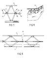
- FIG. 8 shows a barrier of the type of that of FIGS. 1 to 3 (one can of course use the same means or similar means for the embodiment of FIGS. 4 to 6), but the sub-stringer 10 is in several sections connected to each other by fittings, such as fitting 17, here of Cardan type.
- the rail 2 and / or the base 1 can also be in several parts (or in one and have elbows).
- Figure 9 already shows an application.
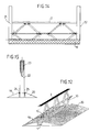
- Figures 10 to 13 show other possible applications.
- Figures 1 to 10 show a base 1 formed of an inverted T-shaped iron (Figure 10) or L-shaped ( Figure 9) and therefore constituting a plinth.
- Figures 11 to 15, on the other hand, show a U-shaped base 1.
- the base 1 in FIGS. 11 and 12 is intended to be placed in an excavation, or as here between two elements 19, 20 forming ramps, the barrier of FIG. 11 being of the type described in connection with FIGS. 1 to 3, and that of FIG. 12 of the type of that described in connection with FIGS. 4 to 6.
- the whole barrier can fold back into the base 1, the assembly forming, for example, a retarder (the arm 2 being sufficiently wide to cover the base 1).
- Figures 14 and 15 show a barrier as previously described, but which is further provided here with two lateral uprights 21 and 22 in which the ends of the heddle 2 are, for example, slidably mounted. It can be a barrier forming a portal, for example.
- An entirely interesting embodiment can of course be directly obtained with the embodiment of FIGS. 4 to 6, the sliding being ensured by the openings 10'a. To do this, simply add amounts in Figure 12.
- the base is mounted between two elements 19, 20 forming ramps.
- the base and the uprights 21 and 22 are articulated at 24, 25 with said elements respectively 19 and 20.
- the barrier In this way, if the barrier is forced with a vehicle in one direction or the other, the barrier will pivot towards the element opposite to the direction of arrival of the vehicle while the other element will be driven in rotation and will block the vehicle. from below.
- the articulation can only be provided on one side.
- the element intended to be raised can be equipped with a stand which unfolds at the time of pivoting to prevent its return to the initial position without special intervention.
Abstract
Description
L'invention concerne une barrière extensible, notamment destinée à constituer un garde-corps ou un barrage, ou encore une barrière de signalisation.The invention relates to an extendable barrier, in particular intended to constitute a railing or a barrier, or even a signaling barrier.
La présente invention est en effet plus particulièrement, mais non exclusivement, destinée à protéger les fosses, tranchées, ou autres, contre les chutes accidentelles des passants ou ouvriers, et d'une manière générale, à protéger de façon temporaire, les excavations à demeure, telles les fosses de garage.The present invention is indeed more particularly, but not exclusively, intended to protect pits, trenches, or the like, against accidental falls of passers-by or workers, and in general, to temporarily protect, permanent excavations , such as garage pits.
Toutefois, non seulement l'invention permet aussi d'équiper une plate-forme, une terrasse, un quai de chargement, ou autre, mais elle permet encore d'assurer un barrage provisoire pour parking, rue piétonne, zones de travaux, etc, ou constituer une simple barrière support pour la signalisation.However, not only does the invention also make it possible to equip a platform, a terrace, a loading dock, or the like, but it also makes it possible to provide a temporary barrier for parking, pedestrian street, work areas, etc. or constitute a simple support barrier for signaling.
Un garde-corps pour fosse de garage, par exemple, comporte une lisse, une sous-lisse et une plinthe.A garage pit railing, for example, has a heald, a sill and a baseboard.
Un tel garde-corps doit pouvoir être installé et désinstallé facilement puisqu'il ne doit pas gêner l'usage de la fosse.Such a guardrail must be able to be installed and uninstalled easily since it must not hinder the use of the pit.
C'est pourquoi on a imaginé des garde-corps du type repliable, comme par exemple ceux décrits dans les brevets Français 2621346 et 2661932 au nom du même inventeur.This is why we imagined railings of the folding type, such as those described in French patents 2621346 and 2661932 in the name of the same inventor.
L'un des inconvénients des dispositifs connus est la nécessité de prévoir un logement pour le garde-corps replié qui constitue une emprise sur la fosse et/ou nécessite des travaux de terrassement.One of the drawbacks of the known devices is the need to provide a housing for the folded railing which constitutes a grip on the pit and / or requires earthworks.
La barrière selon l'invention permet entre autre d'éviter cet inconvénient.The barrier according to the invention makes it possible inter alia to avoid this drawback.
L'invention propose en effet une barrière extensible comportant au moins une lisse et une sous-lisse, mais qui est remarquable en ce que la lisse est soutenue par au moins deux losanges mécaniques écartés l'un de l'autre et formés chacun de quatre bras articulés entre eux par leurs extrémités, en ce que la lisse est fixée sur l'une des articulations de chaque losange, dite articulation de lisse, l'articulation diamétralement opposée, dite articulation de sol, étant destinée à être fixée au sol ou sur un élément à fixer ou poser au sol, tandis que la sous-lisse est constituée par au moins une tige parallèle à la lisse qui traverse les deux autres articulations de chaque losange, dites articulations de sous-lisse, ou est traversée par celles-ci, et qu'au moins un système de blocage est prévu pour bloquer la barrière dans au moins une position d'utilisation.The invention indeed provides an extendable barrier comprising at least one heald and one sub-heald, but which is remarkable in that the heald is supported by at least two mechanical diamonds separated from one another and each formed of four arms hinged together at their ends, in that the heald is fixed to one of the articulations of each rhombus, called heald articulation, the diametrically opposite articulation, called ground articulation, being intended to be fixed to the ground or on an element to be fixed or placed on the ground, while the sub-rail is constituted by at least one rod parallel to the rail which crosses the two other joints of each rhombus, called under-hinge joints, or is crossed by them, and that at least one blocking system is provided for blocking the barrier in at least one position of use.
On comprend qu'une telle barrière est extensible vers le haut, la lisse et la sous-lisse pouvant ainsi être soulevées ou descendues verticalement (pour une installation horizontale).It is understood that such a barrier is extendable upwards, the heald and the sub-heald can thus be raised or lowered vertically (for a horizontal installation).
Selon un mode de réalisation, le système de blocage comporte sur au moins l'une des articulations de sous-lisse pour chaque losange, une bague taraudée, destinée à venir en prise avec une partie filetée de la tige de sous-lisse.According to one embodiment, the blocking system comprises on at least one of the sub-hinge joints for each diamond, a threaded ring, intended to come into engagement with a threaded part of the sub-smooth rod.
Avantageusement dans ce cas, un moyen d'entraînement en rotation est en outre prévu pour être en prise avec la tige de sous-lisse de telle sorte que la rotation de celle-ci entraîne l'écartement, ou le rapprochement, des articulations de sous-lisse et réciproquement le rapprochement ou l'écartement des articulations de lisse et de sol. De préférence aussi, la tige de sous-lisse présente pour chaque losange une partie filetée pour l'une seulement des articulations de sous-lisse dudit losange et une partie lisse pour l'autre articulation de sous-lisse, celle-ci comportant une bague dans laquelle ladite tige de sous-lisse peut coulisser librement.Advantageously in this case, a rotational drive means is further provided to be engaged with the sub-rail rod so that the rotation of the latter causes the spacing, or the approximation, of the sub articulations. -smooth and vice versa the approximation or spacing of the heald and ground joints. Preferably also, the sub-arm rod has for each rhombus a threaded part for only one of the sub-hinge joints of said rhombus and a smooth part for the other sub-hinge articulation, the latter comprising a ring wherein said sub-arm rod can slide freely.
Selon un autre mode de réalisation, éventuellement à actionnement manuel, le système de blocage comporte pour chaque losange et sur au moins l'une des articulations de sous-lisse, un cliquet destiné à venir en prise avec au moins un cran ménagé sur la tige de sous-lisse, laquelle est rendue rotative pour pouvoir se dégager du cliquet par simple rotation.According to another embodiment, possibly with manual actuation, the locking system comprises for each rhombus and on at least one of the sub-hinge joints, a pawl intended to come into engagement with at least one notch formed on the rod sub-arm, which is made rotatable to be able to disengage from the pawl by simple rotation.
Par exemple dans ce cas, au moins un contrepoids est prévu pour maintenir la tige de sous-lisse dans une position dans laquelle les crans dont elle est munie, sont tournés vers les cliquets.For example in this case, at least one counterweight is provided to hold the sub-arm rod in a position in which the notches with which it is provided, are turned towards the pawls.
Une telle barrière peut en outre être constituée par plusieurs barrières élémentaires raccordées entre elles par des moyens qui assujettissent à volonté en rotation les sous-lisses, tandis qu'un moyen de verrouillage en rotation peut être prévu sur au moins l'une desdites barrières élémentaires.Such a barrier can also be constituted by several elementary barriers connected together by means which subject the sub-rails to rotation as desired, while a means for locking in rotation can be provided on at least one of said elementary barriers. .
Selon un mode de réalisation particulièrement avantageux, le système de blocage comporte pour certains au moins des losanges un vérin à double effet dont la tige agit sur l'un des bras dudit losange, tandis que les articulations de sous-lisse sont montées coulissantes dans la sous-lisse de telle sorte que l'actionnement du vérin entraîne l'écartement, ou le rapprochement, des articulations de sous-lisse et réciproquement, le rapprochement ou l'écartement des articulations de lisse et de sol. De préférence dans ce cas, le cylindre du vérin est positionné sensiblement au niveau du sol, parallèlement à la sous-lisse et à la lisse, tandis que la tige dudit vérin est articulée par au moins une biellette à l'un des bras voisin de l'articulation de sol dudit losange.According to a particularly advantageous embodiment, the blocking system includes, for some at least of the diamonds, a double-acting cylinder whose rod acts on one of the arms of said diamond, while the sub-arm joints are slidably mounted in the sub-arm so that actuation of the actuator causes the sub-arm articulations to move apart, or reciprocally, and vice versa, the approximation or the spacing of the heald and floor joints. Preferably in this case, the cylinder of the jack is positioned substantially at ground level, parallel to the sub-beam and to the beam, while the rod of said cylinder is articulated by at least one link to one of the arms neighboring the ground joint of said rhombus.
L'extrémité de la tige du vérin peut, par exemple, être articulée à la biellette par l'intermédiaire d'au moins un galet de roulement.The end of the cylinder rod can, for example, be articulated to the link by means of at least one roller.
Pour notamment assurer un soulèvement bien parallèle de la lisse, l'une des deux articulations de sous-lisse d'au moins certains des losanges sont reliées entre elles par une barre de liaison. Avantageusement aussi, au moins certaines des articulations de sous-lisse sont sollicitées par un ressort de compression faisant notamment office de moyen amortisseur à la descente.In particular to ensure a well parallel lifting of the heddle, one of the two sub-hinge joints of at least some of the diamonds are connected together by a connecting bar. Advantageously also, at least some of the sub-hinge joints are stressed by a compression spring acting in particular as a damping means on the descent.
Pour permettre des applications variées, un mode de réalisation est remarquable en ce que la tige de sous-lisse présente plusieurs tronçons reliés entre eux par des raccords articulés permettant ainsi de constituer une barrière en ligne brisée.To allow various applications, an embodiment is remarkable in that the sub-rail rod has several sections connected to each other by articulated connections thus making it possible to constitute a barrier in a broken line.
L'articulation de sol est, par exemple, fixée à un socle formant au moins une plinthe, ledit socle étant destiné à être fixé ou à reposer au sol.The floor joint is, for example, fixed to a base forming at least one plinth, said base being intended to be fixed or to rest on the ground.
Le socle peut présenter la forme d'un T renversé, mais aussi la forme d'un U.The base can have the shape of an inverted T, but also the shape of a U.
Le socle peut en outre être destiné à être disposé dans une excavation prévue à cet effet.The base can also be intended to be placed in an excavation provided for this purpose.
Dans ce cas et selon un mode de réalisation, le socle est, par exemple, encadré de part et d'autre de sa longueur par des éléments formant rampe et il est articulé à au moins l'un desdits éléments qui repose au sol de telle sorte que l'autre élément se soulève lorsque la barrière est forcée vers l'élément articulé.In this case and according to one embodiment, the base is, for example, framed on either side of its length by elements forming a ramp and it is articulated to at least one of said elements which rests on the ground of such so that the other element is raised when the barrier is forced towards the articulated element.
Selon les applications, il est possible encore de prévoir que les extrémités de la lisse soient montées coulissant dans deux montants latéraux, des moyens pouvant en outre être prévus dans au moins l'un des montants pour actionner la barrière en agissant sur la lisse.Depending on the applications, it is also possible to provide for the ends of the heddle to be slidably mounted in two lateral uprights, means which can also be provided in at least one of the uprights to activate the barrier by acting on the arm.
L'invention sera bien comprise et d'autres particularités apparaîtront à la lecture de la description qui va suivre et qui se réfère aux dessins annexés dans lesquels:
- les figures 1, 2 et 3 montrent une barrière selon l'invention dans trois positions, respectivement basse, intermédiaire et haute,
- les figures 4, 5 et 6 correspondent aux figures 1 à 3, selon un autre mode de réalisation,
- la figure 7 montre en partie un autre mode de réalisation pourvu d'un autre système de blocage,
- la figure 8 montre un raccordement particulier entre deux éléments de barrière,
- la figure 9 représente une application rendue possible grâce à un raccordement du type de celui de la figure 8,
- les figures 10 à 15 montrent des applications possibles des modes de réalisation représentés sur les figures précédentes.
- FIGS. 1, 2 and 3 show a barrier according to the invention in three positions, respectively low, intermediate and high,
- FIGS. 4, 5 and 6 correspond to FIGS. 1 to 3, according to another embodiment,
- FIG. 7 partially shows another embodiment provided with another blocking system,
- FIG. 8 shows a particular connection between two barrier elements,
- FIG. 9 represents an application made possible by a connection of the type of that of FIG. 8,
- Figures 10 to 15 show possible applications of the embodiments shown in the previous figures.
Une barrière selon l'invention, telle que représentée sur les figures 1 à 6, comporte un socle 1 destiné à être fixé ou posé au sol, ou sur tout élément solidaire de celui-ci, et une lisse 2 sous la forme d'une barre (les pièces identiques d'un mode de réalisation à l'autre ayant les mêmes références).A barrier according to the invention, as shown in Figures 1 to 6, comprises a
La lisse 2 est fixée de manière mobile au socle 1, au moyen de bras articulés formant des losanges tels que les losanges 3 et 3'.The
Dans le mode de réalisation des figures 1 à 3, il y a deux losanges 3 et dans le mode de réalisation des figures 4 à 6, on utilise trois losanges 3' (il pourrait bien sûr y en avoir plus).In the embodiment of Figures 1 to 3, there are two
Comme le montrent les figures, chaque losange 3, 3' est constitué de quatre bras articulés entre eux.As shown in the figures, each
Le socle 1 et la lisse 2 comportent en fait des pièces respectivement 4 et 5 sur lesquelles sont articulées les extrémités correspondantes de deux bras de chaque losange et c'est pourquoi les pièces 4 et 5 seront dénommées ci-après articulations respectivement de sol et de lisse.The
En fait, on comprend parfaitement que les bras du losange pourraient être directement articulés entre eux sans l'intermédiaire des pièces 4 et 5.In fact, it is perfectly understood that the arms of the rhombus could be directly articulated with one another without the intermediary of
Les deux autres articulations 6, 6' et 7, 7', sont dites de sous-lisse pour les raisons qui seront comprises ci-après. Dans le mode de réalisation des figures 1 à 3, les articulations de sous-lisse 6, 7 comportent pour l'une 6, une bague taraudée 8 et pour l'autre 7, une bague lisse 9.The other two
Les bagues 8 et 9 des articulations 6 et 7 sont traversées par la sous-lisse formée d'au moins une barre ou tige 10.The
La tige 10 présente ici des parties 10a filetées et des parties 10b lisses.The
Les parties filetées 10a sont destinées à coopérer avec les bagues taraudées 8 et les parties lisses 10b sont destinées à traverser librement les bagues 9.The threaded
De la sorte, on comprend qu'une rotation de la tige 10 de sous-lisse permet par vissage et dévissage, de rapprocher ou écarter les articulations 6 et 7 et en même temps bien sûr respectivement d'écarter ou de rapprocher les articulations 4 et 5 et donc de soulever ou abaisser la lisse 2 et la tige 10 de sous-lisse.In this way, it is understood that a rotation of the
Pour assurer cette rotation, on a prévu ici un moteur 11 électrique, hydraulique, pneumatique, ou autre.To ensure this rotation, an electric, hydraulic, pneumatic, or
Les dimensions sont telles qu'en position repliée (figure 1), tous les éléments se logent dans le socle 1.The dimensions are such that in the folded position (Figure 1), all the elements are housed in the
On comprend que la tige de sous-lisse présente ici plusieurs fonctions.It is understood that the sub-arm rod has several functions here.
Elle constitue d'abord une sous-lisse nécessaire, voire obligatoire pour la protection, mais également un organe de commande et de blocage de la barrière.It firstly constitutes a necessary, or even mandatory, sub-arm for protection, but also a control and blocking member for the barrier.
On peut envisager plusieurs hauteurs possibles d'élévation selon les utilisations, la figure 3 montrant une élévation maximale en fonction de la longueur prévue pour les parties filetées de la tige 10.We can consider several possible elevation heights depending on the uses, Figure 3 showing a maximum elevation depending on the length provided for the threaded parts of the
Il est clair toutefois que toute la tige 10 pourrait être filetée.It is clear, however, that the
Dans le mode de réalisation des figures 4 à 6, les articulations de sous-lisse 6', 7' sont également traversées par une tige 10' de sous-lisse, mais ici chaque articulation 6', 7' comporte un axe qui traverse une lumière correspondante 10'a aménagée dans ladite tige de sous-lisse (voir aussi figure 12 pour une vue en perspective).In the embodiment of FIGS. 4 to 6, the
Il n'y a donc pas ici de partie filetée, ni de moteur 11.There is therefore no threaded part here, nor a
Par contre, on peut voir que les deux losanges 3' d'extrémité sont équipés de vérins 26, par exemple hydrauliques, dont les cylindres sont disposés dans le socle 1 à l'opposé l'un de l'autre, parallèlement audit socle et donc parallèlement à la lisse 2 et à la tige 10' de sous-lisse.On the other hand, it can be seen that the two
Les tiges 27 des cylindres 26 sont articulées par l'intermédiaire d'un galet 28 à une biellette double 29, elle-même articulée à l'un des bras du losange voisin de l'articulation 4 de sol, les références précitées 27 à 29 étant seulement indiquées sur l'un des vérins 26 qui équipe l'un des losanges 3' de la figure 6 pour éviter des répétitions inutiles.The
En outre, dans ce mode de réalisation particulier et tout à fait avantageux des figures 4 à 6, l'une des articulations de sous-lisse de chaque losange, en l'occurrence ici les articulations 6', sont reliées entre elles par une barre de liaison 30.In addition, in this particular and entirely advantageous embodiment of FIGS. 4 to 6, one of the articulations of the sub-arm of each rhombus, in this case here the
On comprend que l'actionnement des vérins 26 permet d'agir sur l'un des bras des losanges d'extrémité et de provoquer ainsi le soulèvement et l'abaissement de la lisse 2 et de la tige 10' de sous-lisse, le système pouvant ainsi prendre, entre autres, les positions montrées sur les figures 4 à 6, la figure 4 montrant la position repliée dans laquelle, comme précédemment, l'ensemble est logé dans le socle 1.It is understood that the actuation of the
La barre de liaison 30 est apparue très utile pour assurer un soulèvement bien parallèle de la lisse et de la sous-lisse. En outre, la barre 30 rigidifie le losange 3' du milieu dépourvu de vérin, car il est clair qu'il n'est pas nécessaire de prévoir un vérin par losange et la disposition représentée avec trois losanges et deux vérins est particulièrement intéressante.The connecting
L'inventeur a également prévu des ressorts de compression (non visibles sur les dessins) disposés dans les lumières 10'a, pour assurer un amortissement à la descente et/ou faciliter le soulèvement.The inventor also provided compression springs (not visible in the drawings) arranged in the openings 10'a, to ensure damping on the descent and / or to facilitate lifting.
En outre, d'autres moyens de blocage de position peuvent être prévus, comme le montre, par exemple, le mode de réalisation de la figure 7 dans lequel en effet, les articulations de sous-lisse, référencées ici 6" et 7", comportent des cliquets 12, 13 destinés à coopérer avec des crans 14, 15 ménagés dans la tige 10" de sous-lisse.In addition, other position locking means can be provided, as shown, for example, in the embodiment of FIG. 7 in which, in fact, the sub-heald joints, referenced here 6 "and 7", have
De plus, dans ce mode de réalisation, un contrepoids 16 oblige la sous-lisse 10" à se présenter de telle manière que les crans 14, 15 dont elle est pourvue soient tournés vers lesdits cliquets 12, 13.In addition, in this embodiment, a
On comprend parfaitement que dans ce mode de réalisation, il suffit de lever la lisse 2 pour provoquer le blocage des cliquets alors qu'il faut tourner la sous-lisse 10" pour dégager ces derniers et replier la barrière. On comprend aussi que le levage de la lisse 2 peut s'effectuer par tout moyen et même bien sûr manuellement.It is perfectly understood that in this embodiment, it suffices to lift the
On peut bien sûr imaginer de raccorder plusieurs barrières du type de la figure 7, des moyens étant prévus pour assujettir à volonté en rotation, les sous-lisses 10". Ces moyens peuvent, par exemple, être aménagés dans les contrepoids 16 qui comportent à cet effet chacun une rainure d'accouplement 16', comme représenté sur la figure 7. En outre, dans ce cas, on peut aussi prévoir un moyen de verrouillage de la rotation d'au moins l'une des barrières, ce moyen comportant, par exemple, un verrou prévu dans au moins l'une des articulations 6", 7", actionnable par une clef. Ce verrouillage peut bien sûr être prévu même si la barrière est en un seul élément.One can of course imagine connecting several barriers of the type of Figure 7, means being provided to subject at will in rotation, the sub-beams 10 ". These means can, for example, be arranged in the
La figure 8 montre une barrière du type de celle des figures 1 à 3 (on peut bien sûr utiliser les mêmes moyens ou des moyens semblables pour le mode de réalisation des figures 4 à 6), mais dont la sous-lisse 10 est en plusieurs tronçons reliés entre eux par des raccords, comme le raccord 17, ici de type à Cardan.FIG. 8 shows a barrier of the type of that of FIGS. 1 to 3 (one can of course use the same means or similar means for the embodiment of FIGS. 4 to 6), but the sub-stringer 10 is in several sections connected to each other by fittings, such as fitting 17, here of Cardan type.
Une telle disposition permet notamment de faire des coudes comme le schématise la barrière de la figure 9 pourvue d'au moins un raccordement 17.Such an arrangement makes it possible in particular to make elbows as shown in the barrier of FIG. 9 provided with at least one
Pour une barrière de ce type, la lisse 2 et/ou le socle 1 peuvent être aussi en plusieurs parties (ou en une seule et présenter des coudes).For a barrier of this type, the
La figure 9 montre déjà une application. Les figures 10 à 13 montrent d'autres applications possibles.Figure 9 already shows an application. Figures 10 to 13 show other possible applications.
Avec deux barrières telles que décrites, on peut, par exemple, protéger une fosse de garage 18, comme représenté sur la figure 10 (c'est à titre d'exemple que l'on utilise ici le mode de réalisation des figures 1 à 3).With two barriers as described, it is possible, for example, to protect a
Les figures 1 à 10 montrent un socle 1 formé d'un fer en T renversé (figure 10) ou en L (figure 9) et constituant donc une plinthe.Figures 1 to 10 show a
Les figures 11 à 15, par contre, montrent un socle 1 en U.Figures 11 to 15, on the other hand, show a
Le socle 1 sur les figures 11 et 12, est destiné à être disposé dans une excavation, ou comme ici entre deux éléments 19, 20 formant des rampes, la barrière de la figure 11 étant du type décrit à propos des figures 1 à 3, et celle de la figure 12 du type de celle décrit à propos des figures 4 à 6.The
On comprend alors que toute la barrière peut se replier dans le socle 1, l'ensemble formant, par exemple, un ralentisseur (la lisse 2 étant suffisamment large pour recouvrir le socle 1).It is therefore understood that the whole barrier can fold back into the
Dans l'application de la figure 13, un seul élément de rampe 19 est prévu, la barrière étant, par exemple, destinée à un quai de débarquement.In the application of FIG. 13, only one
Les figures 14 et 15 montrent une barrière telle que précédemment décrite, mais qui est en outre pourvue ici de deux montants latéraux 21 et 22 dans lesquels les extrémités de la lisse 2 sont, par exemple, montées de manière coulissante. Il peut s'agir d'une barrière formant portail, par exemple. Un mode de réalisation tout à fait intéressant peut bien sûr être directement obtenu avec le mode de réalisation des figures 4 à 6, le coulissement étant assuré par les lumières 10'a. Pour cela, il suffit simplement de rajouter des montants sur la figure 12.Figures 14 and 15 show a barrier as previously described, but which is further provided here with two
Pour actionner la barrière des figures 14 et 15, on a prévu au moins un vérin 23 aménagé dans au moins l'un des montants, ledit vérin étant destiné à agir sur la lisse 2. Toutefois, avec un dispositif tel que celui de la figure 12, les vérins d'actionnement sont disposés comme déjà dit dans le socle 1.To actuate the barrier of Figures 14 and 15, there is provided at least one
Comme dans le cas des figures 11 et 12, le socle est monté entre deux éléments 19, 20 formant rampes.As in the case of FIGS. 11 and 12, the base is mounted between two
En outre, comme le montre plus particulièrement la figure 15, le socle et les montants 21 et 22 sont articulés en 24, 25 avec lesdits éléments respectivement 19 et 20.In addition, as shown more particularly in FIG. 15, the base and the
De la sorte, si on force la barrière avec un véhicule dans un sens ou dans l'autre, la barrière pivotera vers l'élément opposé au sens d'arrivée du véhicule tandis que l'autre élément sera entraîné en rotation et bloquera le véhicule par le dessous.In this way, if the barrier is forced with a vehicle in one direction or the other, the barrier will pivot towards the element opposite to the direction of arrival of the vehicle while the other element will be driven in rotation and will block the vehicle. from below.
Il est évident que dans ce cas, on peut ne prévoir l'articulation que d'un seul côté.It is obvious that in this case, the articulation can only be provided on one side.
De plus, l'élément destiné à se relever peut être équipé d'une béquille qui se déplie au moment du pivotement pour en interdire le retour en position initiale sans une intervention spéciale.In addition, the element intended to be raised can be equipped with a stand which unfolds at the time of pivoting to prevent its return to the initial position without special intervention.
Claims (19)
- Extensible barrier comprising at least one top rail (2) and a lower rail (10, 10' 10''), characterised in that the top rail (2) is supported by at least two mechanical rhombuses (3, 3') separated from one another and each formed by four arms articulated together by their ends, in that the top rail (2) is fixed to one of the articulations of each rhombus, called the top rail articulation (5), the diametrically opposing articulation, called the ground articulation (4), being designed to be fixed to the ground or to an element (1) to be fixed or laid on the ground, while the lower rail is constituted by at least one rod (10, 10' 10'') which is parallel to the top rail and passes through the other two articulations (6, 7; 6', 7'; 6'', 7'') of each rhombus, called lower rail articulations, or is traversed by these, and in that at least one locking system is provided to lock the barrier in at least one position of use.
- Barrier according to claim 1, characterised in that on at least one of the lower rail articulations (6) of each rhombus the locking system comprises a tapped ring (8), designed to engage with a threaded portion (10a) of the lower rail rod (10).
- Barrier according to claim 2, characterised in that a means of entrainment in rotation (11) is additionally provided so as to be in engagement with the lower rail rod (10) such that the rotation of the latter leads to the widening or the narrowing of the gap between the lower rail articulations (6, 7) and reciprocally the narrowing or the widening of the gap between the top rail articulations (5) and the ground articulations (4).
- Barrier according to one of claims 2 and 3, characterised in that for each rhombus (3) the lower rail rod (10) exhibits a threaded portion (10a) for just one (6) of the lower rail articulations of said rhombus and a smooth portion (10b) for the other lower rail articulation (7), the latter comprising a ring (9) in which said lower rail rod can slide freely.
- Barrier according to claim 1, characterised in that for each rhombus and on at least one of the lower rail articulations (6", 7") the locking system comprises a pawl (12, 13) designed to engage with at least one notch (14, 15) formed on the lower rail rod (10") which is made capable of rotation in order to be able to disengage from the pawl through simple rotation.
- Barrier according to claim 5, characterised in that at least one counter weight (16) is provided to maintain the lower rail rod (10") in a position in which the notches (14, 15) formed in it are turned towards the pawls.
- Barrier according to one of claims 1 to 6, characterised in that it is constituted by a plurality of elementary barriers connected together by means (16') which control the lower rails (10") in rotation at will, while a rotational locking means can be provided on at least one of said elementary barriers.
- Barrier according to claim 1, characterised in that for at least some of the rhombuses (3') the locking system comprises a double-acting jack (26) whose rod (27) acts on one of the arms of said rhombus (3'), while the lower rail articulations (6', 7') are mounted slidingly in the lower rail (10') such that the operation of the jack (26) causes the widening or the narrowing of the gap between the lower rail articulations (6', 7') and reciprocally the narrowing or the widening of the gap between the top rail articulations (5) and the ground articulations (4).
- Barrier according to claim 8, characterised in that the cylinder of the jack is positioned substantially at ground level, parallel to the lower rail (10') and to the top rail (2), while the rod (27) of said jack is articulated through at least one link rod (29) to the adjacent one of the arms of the ground articulation (4) of said rhombus.
- Barrier according to claim 9, characterised in that the end of the rod (27) of the jack (26) is articulated to the link rod (29) through the intermediary of at least one roller (28).
- Barrier according to one of claims 8 to 10, characterised in that one (6') of the two lower rail articulations (10') of at least some of the rhombuses (3') are linked together by a linking bar (30).
- Barrier according to one of claims 8 to 11, characterised in that at least some of the lower rail articulations (7') are subjected to the action of a compression spring serving notably as a damper during lowering.
- Barrier according to one of claims 1 to 12, characterised in that the lower rail rod exhibits a plurality of sections linked together by articulated connectors (17), thus making it possible to form a barrier in a jagged line.
- Barrier according to one of claims 1 to 13, characterised in that the ground articulation (4) is fixed to a base (1) forming at least one plinth, said base being designed to be fixed or to rest on the ground.
- Barrier according to claim 14, characterised in that the base (1) takes the form of a U.
- Barrier according to one of claims 14 and 15, characterised in that the base (1) is designed to be disposed in an excavation provided for that purpose.
- Barrier according to claim 16, characterised in that the base (1) is framed on either side of its length by elements (19, 20) forming a ramp and in that it is articulated (24, 25) to at least one of said elements (19, 20) which rests on the ground such that the other element is raised when the barrier is forced towards the articulated element.
- Barrier according to one of claims 1 to 17, characterised in that the ends of the top rail (2) are mounted slidingly in two side uprights (21, 22).
- Barrier according to claim 18, characterised in that means (23) are provided in at least one of the uprights (21, 22) to operate the barrier by acting on the top rail (2).
Applications Claiming Priority (3)
| Application Number | Priority Date | Filing Date | Title |
|---|---|---|---|
| FR9214932A FR2699208B1 (en) | 1992-12-11 | 1992-12-11 | Extendable barrier. |
| FR9214932 | 1992-12-11 | ||
| PCT/FR1993/001221 WO1994013885A1 (en) | 1992-12-11 | 1993-12-10 | Collapsible barrier |
Publications (2)
| Publication Number | Publication Date |
|---|---|
| EP0628111A1 EP0628111A1 (en) | 1994-12-14 |
| EP0628111B1 true EP0628111B1 (en) | 1997-09-10 |
Family
ID=9436469
Family Applications (1)
| Application Number | Title | Priority Date | Filing Date |
|---|---|---|---|
| EP94902012A Expired - Lifetime EP0628111B1 (en) | 1992-12-11 | 1993-12-10 | Collapsible barrier |
Country Status (9)
| Country | Link |
|---|---|
| EP (1) | EP0628111B1 (en) |
| JP (1) | JPH07504006A (en) |
| AT (1) | ATE158042T1 (en) |
| AU (1) | AU5653794A (en) |
| BR (1) | BR9305869A (en) |
| CA (1) | CA2129529A1 (en) |
| DE (1) | DE69313834D1 (en) |
| FR (1) | FR2699208B1 (en) |
| WO (1) | WO1994013885A1 (en) |
Families Citing this family (22)
| Publication number | Priority date | Publication date | Assignee | Title |
|---|---|---|---|---|
| GB2274664B (en) * | 1993-01-28 | 1996-01-24 | Mckenzie Martin Limited | Improvements in or relating to safety barriers |
| JP3846971B2 (en) * | 1997-05-22 | 2006-11-15 | 宮田自動機販売株式会社 | Vehicle entrance fence |
| DE19723315C2 (en) * | 1997-06-04 | 2000-12-28 | Haeberlen Guenter | Flow blocking device |
| EP1757735A3 (en) * | 1998-05-26 | 2007-07-11 | General Dynamics Ordnance and Tactical Systems, Inc. | Non-lethal, rapidly deployed, vehicle immobilizer system |
| GB2349900B (en) * | 1999-05-13 | 2001-03-21 | Dennis Victor Cooke | Folding fence/barrier |
| AP2254A (en) * | 2004-03-31 | 2011-07-21 | Universal Safety Response Inc | Net and mat. |
| ES2292283B1 (en) * | 2005-02-23 | 2009-02-01 | Jose Antonio Navarro Biota | FOLDING PROTECTOR ASSEMBLY FOR WORKS. |
| FR2886660B1 (en) * | 2005-06-02 | 2007-09-07 | Somep Ind Soc Par Actions Simp | GUARD RAIL AND TELECOMMUNICATIONS ANTENNA SUPPORT IMPLEMENTING SUCH GUARD BODY |
| NL1031600C2 (en) * | 2006-04-14 | 2007-10-16 | Altrex Bv | Collapsible safety railing for scaffolding, has railing uprights movably connected to beam so that railing can be secured to scaffolding platform support frames whilst folded away |
| FR2922243A1 (en) * | 2007-10-11 | 2009-04-17 | Richard Lahaie | Removable and retractable fence device for realizing i.e. safety enclosure, around e.g. in-ground swimming pool, has case with internal width equal to height of barrier in folded position and height equal to larger thickness of barrier |
| AT508699B1 (en) * | 2009-09-10 | 2011-06-15 | Wirrer Georg Mag | HEBETORSYSTEM |
| MY163912A (en) * | 2010-02-11 | 2017-11-15 | Johnson & Nicholson M Sdn Bhd | Height adjustable speed bump |
| EP2418324B1 (en) * | 2010-07-22 | 2012-12-26 | Jörg P. Junker | Crash barrier assembly |
| US10724257B2 (en) | 2014-11-26 | 2020-07-28 | Control Dynamics, Inc. | Vertically raising safety rail with dual curtain assembly |
| US9745762B2 (en) | 2014-11-26 | 2017-08-29 | Control Dynamics, Inc. | Vertically raising safety rail |
| CN104963553B (en) * | 2015-07-14 | 2017-11-03 | 国电联合动力技术有限公司 | A kind of electric power safety rail |
| CN106988601A (en) * | 2017-04-28 | 2017-07-28 | 国网山东省电力公司临朐县供电公司 | Switch cubicle is special to block net support |
| IT201700111952A1 (en) * | 2017-10-05 | 2019-04-05 | Faac Spa | BOLLARD DEVICE. |
| CN108103985A (en) * | 2017-12-23 | 2018-06-01 | 郭舒洋 | A kind of anti-riot car bumper device |
| CN110043112B (en) * | 2019-04-22 | 2020-10-23 | 嘉兴考普诺机械科技有限公司 | Early warning double-electric-network detection railway fence for railway crossing |
| JP6703680B1 (en) * | 2019-04-24 | 2020-06-03 | 株式会社エム・システム技研 | Warning device |
| KR102607286B1 (en) * | 2023-07-31 | 2023-11-29 | (주)세진에프에이 | High And Low Controlled Fence |
Family Cites Families (7)
| Publication number | Priority date | Publication date | Assignee | Title |
|---|---|---|---|---|
| US1595164A (en) * | 1925-08-08 | 1926-08-10 | Charles F Mundy | Door-jamb setter |
| FR1191803A (en) * | 1958-02-21 | 1959-10-22 | Jaquemet & Mesnet Ets | Folding hinged grid |
| FR1314328A (en) * | 1962-02-09 | 1963-01-04 | Security grille for windows and doors | |
| CH437735A (en) * | 1966-03-04 | 1967-06-15 | Nayagam Suzanne | Formwork device |
| AT322192B (en) * | 1973-07-13 | 1975-05-12 | Aichinger Franz | DEVICE FOR RECESSING OPENINGS, IN PARTICULAR DOOR OPENINGS, IN A MASONRY |
| FR2566453B1 (en) * | 1984-06-26 | 1988-04-29 | Fichet Bauche | EXTENSIBLE GRID FOR THE PROTECTION OF A BAY |
| FR2661932A1 (en) * | 1990-05-11 | 1991-11-15 | Anglade Rene | Foldable guard rail |
-
1992
- 1992-12-11 FR FR9214932A patent/FR2699208B1/en not_active Expired - Fee Related
-
1993
- 1993-12-10 JP JP6513872A patent/JPH07504006A/en active Pending
- 1993-12-10 AU AU56537/94A patent/AU5653794A/en not_active Abandoned
- 1993-12-10 EP EP94902012A patent/EP0628111B1/en not_active Expired - Lifetime
- 1993-12-10 WO PCT/FR1993/001221 patent/WO1994013885A1/en active IP Right Grant
- 1993-12-10 BR BR9305869A patent/BR9305869A/en unknown
- 1993-12-10 DE DE69313834T patent/DE69313834D1/en not_active Expired - Lifetime
- 1993-12-10 AT AT94902012T patent/ATE158042T1/en not_active IP Right Cessation
- 1993-12-10 CA CA002129529A patent/CA2129529A1/en not_active Abandoned
Also Published As
| Publication number | Publication date |
|---|---|
| ATE158042T1 (en) | 1997-09-15 |
| CA2129529A1 (en) | 1994-06-23 |
| FR2699208B1 (en) | 1995-03-24 |
| JPH07504006A (en) | 1995-04-27 |
| EP0628111A1 (en) | 1994-12-14 |
| FR2699208A1 (en) | 1994-06-17 |
| DE69313834D1 (en) | 1997-10-16 |
| AU5653794A (en) | 1994-07-04 |
| BR9305869A (en) | 1997-08-19 |
| WO1994013885A1 (en) | 1994-06-23 |
Similar Documents
| Publication | Publication Date | Title |
|---|---|---|
| EP0628111B1 (en) | Collapsible barrier | |
| CA2312411C (en) | Median strip cut-off device | |
| FR2897624A1 (en) | Automatic trap system for use in e.g. pipe, has trap raised to simultaneously lead to automatic deployment of transversal and lateral guide rails with respect to each other till vertical positioning of rails | |
| FR2605619A1 (en) | REPLIABLE MACHINE FOR HANDLING AND LIFTING LOADS | |
| FR2775992A1 (en) | Vehicle control bollard, vertically retractable below street level | |
| FR2661932A1 (en) | Foldable guard rail | |
| FR2889223A1 (en) | Corbel work structure for e.g. public work field, has control unit deported from articulated columns and permitting blocking and unblocking of articulation of columns by operator placed beyond folding zone of columns | |
| FR2863291A1 (en) | Safety railing for balcony extension of scaffold frame has extending side sections to adjust to the size of the structure | |
| WO1992014674A1 (en) | Spacing or lifting device | |
| FR2604469A1 (en) | Fastening device for a service platform or facade scaffolding | |
| EP1091046B1 (en) | Closing device for a manhole or an inspection shaft | |
| EP1334236B1 (en) | Extensible barrier on rollers with manually extensible and retractable pivoting elements | |
| EP0870725B1 (en) | Tower crane with a telescopic ladder and a mobile element guided on this ladder | |
| FR2739637A1 (en) | Support pivot for pivoting panel | |
| FR3044700A1 (en) | CLOSURE DEVICE | |
| EP0258919B1 (en) | Device for making access possible in a building to an exit closed by a trap door | |
| FR2520788A1 (en) | SAFETY BARRIER FOR PLATFORM | |
| FR2817902A1 (en) | Secure locking device for access to ladder safety hoop comprises movable cover with panel, covering ladder immediately below hoop, carrying hoop obturator at upper end | |
| FR2937026A1 (en) | Lifting device for e.g. still camera, has three sets of scissor pairs connected to base, where each set has two sides connected to adjacent set by connection elements such that sets and connection elements form closed structure | |
| FR2599422A1 (en) | Extension ladder for a room with a central access shaft | |
| FR2932512A1 (en) | Form panel support platform's articulated foldable spacer for use during construction of building, has joint placed between one of branches and leg, and return spring to maintain branch in non-alignment position with other branch | |
| BE526897A (en) | ||
| FR2799894A1 (en) | RETRACTABLE DISTRIBUTION TERMINAL | |
| FR2810027A1 (en) | Theatre back drop hoist cable has main cable with brake engaging parallel auxiliary cable | |
| EP1900879B1 (en) | Supporting panel |
Legal Events
| Date | Code | Title | Description |
|---|---|---|---|
| PUAI | Public reference made under article 153(3) epc to a published international application that has entered the european phase |
Free format text: ORIGINAL CODE: 0009012 |
|
| AK | Designated contracting states |
Kind code of ref document: A1 Designated state(s): AT BE CH DE DK ES FR GB GR IE IT LI LU MC NL PT SE |
|
| 17P | Request for examination filed |
Effective date: 19941222 |
|
| GRAG | Despatch of communication of intention to grant |
Free format text: ORIGINAL CODE: EPIDOS AGRA |
|
| 17Q | First examination report despatched |
Effective date: 19960201 |
|
| GRAH | Despatch of communication of intention to grant a patent |
Free format text: ORIGINAL CODE: EPIDOS IGRA |
|
| GRAH | Despatch of communication of intention to grant a patent |
Free format text: ORIGINAL CODE: EPIDOS IGRA |
|
| GRAA | (expected) grant |
Free format text: ORIGINAL CODE: 0009210 |
|
| AK | Designated contracting states |
Kind code of ref document: B1 Designated state(s): AT BE CH DE DK ES FR GB GR IE IT LI LU MC NL PT SE |
|
| PG25 | Lapsed in a contracting state [announced via postgrant information from national office to epo] |
Ref country code: NL Free format text: LAPSE BECAUSE OF FAILURE TO SUBMIT A TRANSLATION OF THE DESCRIPTION OR TO PAY THE FEE WITHIN THE PRESCRIBED TIME-LIMIT Effective date: 19970910 Ref country code: IT Free format text: LAPSE BECAUSE OF FAILURE TO SUBMIT A TRANSLATION OF THE DESCRIPTION OR TO PAY THE FEE WITHIN THE PRE;WARNING: LAPSES OF ITALIAN PATENTS WITH EFFECTIVE DATE BEFORE 2007 MAY HAVE OCCURRED AT ANY TIME BEFORE 2007. THE CORRECT EFFECTIVE DATE MAY BE DIFFERENT FROM THE ONE RECORDED.SCRIBED TIME-LIMIT Effective date: 19970910 Ref country code: GR Free format text: LAPSE BECAUSE OF FAILURE TO SUBMIT A TRANSLATION OF THE DESCRIPTION OR TO PAY THE FEE WITHIN THE PRESCRIBED TIME-LIMIT Effective date: 19970910 Ref country code: GB Free format text: LAPSE BECAUSE OF FAILURE TO SUBMIT A TRANSLATION OF THE DESCRIPTION OR TO PAY THE FEE WITHIN THE PRESCRIBED TIME-LIMIT Effective date: 19970910 Ref country code: ES Free format text: THE PATENT HAS BEEN ANNULLED BY A DECISION OF A NATIONAL AUTHORITY Effective date: 19970910 Ref country code: DK Free format text: LAPSE BECAUSE OF NON-PAYMENT OF DUE FEES Effective date: 19970910 Ref country code: AT Effective date: 19970910 |
|
| REF | Corresponds to: |
Ref document number: 158042 Country of ref document: AT Date of ref document: 19970915 Kind code of ref document: T |
|
| REG | Reference to a national code |
Ref country code: CH Ref legal event code: EP |
|
| REF | Corresponds to: |
Ref document number: 69313834 Country of ref document: DE Date of ref document: 19971016 |
|
| PG25 | Lapsed in a contracting state [announced via postgrant information from national office to epo] |
Ref country code: SE Effective date: 19971210 Ref country code: PT Effective date: 19971210 Ref country code: LU Free format text: LAPSE BECAUSE OF NON-PAYMENT OF DUE FEES Effective date: 19971210 |
|
| PG25 | Lapsed in a contracting state [announced via postgrant information from national office to epo] |
Ref country code: DE Free format text: LAPSE BECAUSE OF FAILURE TO SUBMIT A TRANSLATION OF THE DESCRIPTION OR TO PAY THE FEE WITHIN THE PRESCRIBED TIME-LIMIT Effective date: 19971211 |
|
| PG25 | Lapsed in a contracting state [announced via postgrant information from national office to epo] |
Ref country code: LI Free format text: LAPSE BECAUSE OF NON-PAYMENT OF DUE FEES Effective date: 19971231 Ref country code: CH Free format text: LAPSE BECAUSE OF NON-PAYMENT OF DUE FEES Effective date: 19971231 Ref country code: BE Free format text: LAPSE BECAUSE OF NON-PAYMENT OF DUE FEES Effective date: 19971231 |
|
| REG | Reference to a national code |
Ref country code: IE Ref legal event code: FG4D Free format text: 76381 |
|
| NLV1 | Nl: lapsed or annulled due to failure to fulfill the requirements of art. 29p and 29m of the patents act | ||
| GBV | Gb: ep patent (uk) treated as always having been void in accordance with gb section 77(7)/1977 [no translation filed] |
Effective date: 19970910 |
|
| PG25 | Lapsed in a contracting state [announced via postgrant information from national office to epo] |
Ref country code: IE Free format text: LAPSE BECAUSE OF NON-PAYMENT OF DUE FEES Effective date: 19980605 |
|
| BERE | Be: lapsed |
Owner name: ANGLADE RENE Effective date: 19971231 |
|
| PG25 | Lapsed in a contracting state [announced via postgrant information from national office to epo] |
Ref country code: MC Free format text: LAPSE BECAUSE OF NON-PAYMENT OF DUE FEES Effective date: 19980630 |
|
| REG | Reference to a national code |
Ref country code: IE Ref legal event code: FD4D Ref document number: 76381 Country of ref document: IE |
|
| PLBE | No opposition filed within time limit |
Free format text: ORIGINAL CODE: 0009261 |
|
| STAA | Information on the status of an ep patent application or granted ep patent |
Free format text: STATUS: NO OPPOSITION FILED WITHIN TIME LIMIT |
|
| REG | Reference to a national code |
Ref country code: CH Ref legal event code: PL |
|
| 26N | No opposition filed | ||
| PGFP | Annual fee paid to national office [announced via postgrant information from national office to epo] |
Ref country code: FR Payment date: 20010628 Year of fee payment: 8 |
|
| PG25 | Lapsed in a contracting state [announced via postgrant information from national office to epo] |
Ref country code: FR Free format text: LAPSE BECAUSE OF NON-PAYMENT OF DUE FEES Effective date: 20020830 |
|
| REG | Reference to a national code |
Ref country code: FR Ref legal event code: ST |