EP0628111B1 - Ausziehbares Geländer - Google Patents
Ausziehbares Geländer Download PDFInfo
- Publication number
- EP0628111B1 EP0628111B1 EP94902012A EP94902012A EP0628111B1 EP 0628111 B1 EP0628111 B1 EP 0628111B1 EP 94902012 A EP94902012 A EP 94902012A EP 94902012 A EP94902012 A EP 94902012A EP 0628111 B1 EP0628111 B1 EP 0628111B1
- Authority
- EP
- European Patent Office
- Prior art keywords
- lower rail
- articulations
- barrier according
- barrier
- rod
- Prior art date
- Legal status (The legal status is an assumption and is not a legal conclusion. Google has not performed a legal analysis and makes no representation as to the accuracy of the status listed.)
- Expired - Lifetime
Links
Images


Classifications
-
- E—FIXED CONSTRUCTIONS
- E04—BUILDING
- E04H—BUILDINGS OR LIKE STRUCTURES FOR PARTICULAR PURPOSES; SWIMMING OR SPLASH BATHS OR POOLS; MASTS; FENCING; TENTS OR CANOPIES, IN GENERAL
- E04H5/00—Buildings or groups of buildings for industrial or agricultural purposes
- E04H5/02—Buildings or groups of buildings for industrial purposes, e.g. for power-plants or factories
- E04H5/06—Pits or building structures for inspection or services
-
- E—FIXED CONSTRUCTIONS
- E01—CONSTRUCTION OF ROADS, RAILWAYS, OR BRIDGES
- E01F—ADDITIONAL WORK, SUCH AS EQUIPPING ROADS OR THE CONSTRUCTION OF PLATFORMS, HELICOPTER LANDING STAGES, SIGNS, SNOW FENCES, OR THE LIKE
- E01F13/00—Arrangements for obstructing or restricting traffic, e.g. gates, barricades ; Preventing passage of vehicles of selected category or dimensions
- E01F13/04—Arrangements for obstructing or restricting traffic, e.g. gates, barricades ; Preventing passage of vehicles of selected category or dimensions movable to allow or prevent passage
- E01F13/044—Arrangements for obstructing or restricting traffic, e.g. gates, barricades ; Preventing passage of vehicles of selected category or dimensions movable to allow or prevent passage the barrier being formed by obstructing members situated on, flush with, or below the traffic surface, e.g. with inflatable members on the surface
-
- E—FIXED CONSTRUCTIONS
- E01—CONSTRUCTION OF ROADS, RAILWAYS, OR BRIDGES
- E01F—ADDITIONAL WORK, SUCH AS EQUIPPING ROADS OR THE CONSTRUCTION OF PLATFORMS, HELICOPTER LANDING STAGES, SIGNS, SNOW FENCES, OR THE LIKE
- E01F13/00—Arrangements for obstructing or restricting traffic, e.g. gates, barricades ; Preventing passage of vehicles of selected category or dimensions
- E01F13/04—Arrangements for obstructing or restricting traffic, e.g. gates, barricades ; Preventing passage of vehicles of selected category or dimensions movable to allow or prevent passage
- E01F13/048—Arrangements for obstructing or restricting traffic, e.g. gates, barricades ; Preventing passage of vehicles of selected category or dimensions movable to allow or prevent passage with obstructing members moving in a translatory motion, e.g. vertical lift barriers, sliding gates
-
- E—FIXED CONSTRUCTIONS
- E04—BUILDING
- E04G—SCAFFOLDING; FORMS; SHUTTERING; BUILDING IMPLEMENTS OR AIDS, OR THEIR USE; HANDLING BUILDING MATERIALS ON THE SITE; REPAIRING, BREAKING-UP OR OTHER WORK ON EXISTING BUILDINGS
- E04G21/00—Preparing, conveying, or working-up building materials or building elements in situ; Other devices or measures for constructional work
- E04G21/32—Safety or protective measures for persons during the construction of buildings
- E04G21/3204—Safety or protective measures for persons during the construction of buildings against falling down
- E04G21/3223—Means supported by building floors or flat roofs, e.g. safety railings
Definitions
- the invention relates to an extendable barrier, in particular intended to constitute a railing or a barrier, or even a signaling barrier.
- the present invention is indeed more particularly, but not exclusively, intended to protect pits, trenches, or the like, against accidental falls of passers-by or workers, and in general, to temporarily protect, permanent excavations , such as garage pits.
- the invention also make it possible to equip a platform, a terrace, a loading dock, or the like, but it also makes it possible to provide a temporary barrier for parking, pedestrian street, work areas, etc. or constitute a simple support barrier for signaling.
- a garage pit railing for example, has a heald, a sill and a baseboard.
- Such a guardrail must be able to be installed and uninstalled easily since it must not hinder the use of the pit.
- One of the drawbacks of the known devices is the need to provide a housing for the folded railing which constitutes a grip on the pit and / or requires earthworks.
- the barrier according to the invention makes it possible inter alia to avoid this drawback.
- the invention indeed provides an extendable barrier comprising at least one heald and one sub-heald, but which is remarkable in that the heald is supported by at least two mechanical diamonds separated from one another and each formed of four arms hinged together at their ends, in that the heald is fixed to one of the articulations of each rhombus, called heald articulation, the diametrically opposite articulation, called ground articulation, being intended to be fixed to the ground or on an element to be fixed or placed on the ground, while the sub-rail is constituted by at least one rod parallel to the rail which crosses the two other joints of each rhombus, called under-hinge joints, or is crossed by them, and that at least one blocking system is provided for blocking the barrier in at least one position of use.
- the blocking system comprises on at least one of the sub-hinge joints for each diamond, a threaded ring, intended to come into engagement with a threaded part of the sub-smooth rod.
- a rotational drive means is further provided to be engaged with the sub-rail rod so that the rotation of the latter causes the spacing, or the approximation, of the sub articulations. -smooth and vice versa the approximation or spacing of the heald and ground joints.
- the sub-arm rod has for each rhombus a threaded part for only one of the sub-hinge joints of said rhombus and a smooth part for the other sub-hinge articulation, the latter comprising a ring wherein said sub-arm rod can slide freely.
- the locking system comprises for each rhombus and on at least one of the sub-hinge joints, a pawl intended to come into engagement with at least one notch formed on the rod sub-arm, which is made rotatable to be able to disengage from the pawl by simple rotation.
- At least one counterweight is provided to hold the sub-arm rod in a position in which the notches with which it is provided, are turned towards the pawls.
- Such a barrier can also be constituted by several elementary barriers connected together by means which subject the sub-rails to rotation as desired, while a means for locking in rotation can be provided on at least one of said elementary barriers.
- the blocking system includes, for some at least of the diamonds, a double-acting cylinder whose rod acts on one of the arms of said diamond, while the sub-arm joints are slidably mounted in the sub-arm so that actuation of the actuator causes the sub-arm articulations to move apart, or reciprocally, and vice versa, the approximation or the spacing of the heald and floor joints.
- the cylinder of the jack is positioned substantially at ground level, parallel to the sub-beam and to the beam, while the rod of said cylinder is articulated by at least one link to one of the arms neighboring the ground joint of said rhombus.
- the end of the cylinder rod can, for example, be articulated to the link by means of at least one roller.
- one of the two sub-hinge joints of at least some of the diamonds are connected together by a connecting bar.
- at least some of the sub-hinge joints are stressed by a compression spring acting in particular as a damping means on the descent.
- the sub-rail rod has several sections connected to each other by articulated connections thus making it possible to constitute a barrier in a broken line.
- the floor joint is, for example, fixed to a base forming at least one plinth, said base being intended to be fixed or to rest on the ground.
- the base can have the shape of an inverted T, but also the shape of a U.
- the base can also be intended to be placed in an excavation provided for this purpose.
- the base is, for example, framed on either side of its length by elements forming a ramp and it is articulated to at least one of said elements which rests on the ground of such so that the other element is raised when the barrier is forced towards the articulated element.
- the ends of the heddle can be slidably mounted in two lateral uprights, means which can also be provided in at least one of the uprights to activate the barrier by acting on the arm.
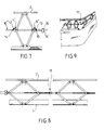
- a barrier according to the invention as shown in Figures 1 to 6, comprises a base 1 intended to be fixed or placed on the ground, or on any element integral with the latter, and a heddle 2 in the form of a bar (identical parts from one embodiment to another having the same references).
- the rail 2 is movably attached to the base 1, by means of articulated arms forming diamonds such as diamonds 3 and 3 '.
- each rhombus 3, 3 ' is made up of four arms hinged together.
- the base 1 and the rail 2 in fact comprise parts respectively 4 and 5 on which the corresponding ends of two arms of each rhombus are articulated, and this is why the parts 4 and 5 will be referred to hereinafter as joints of ground and smooth.
- the other two joints 6, 6 'and 7, 7' are said to be sub-smooth for the reasons which will be understood below.
- the sub-hinge joints 6, 7 comprise for one 6, a threaded ring 8 and for the other 7, a smooth ring 9.
- the rings 8 and 9 of the joints 6 and 7 are crossed by the sub-rail formed by at least one bar or rod 10.
- the rod 10 here has threaded parts 10a and smooth parts 10b.
- the threaded parts 10a are intended to cooperate with the threaded rings 8 and the smooth parts 10b are intended to pass freely through the rings 9.
- a rotation of the sub-rail rod 10 makes it possible, by screwing and unscrewing, to bring the joints 6 and 7 closer or apart and at the same time of course respectively to move the joints 4 and 5 and therefore raise or lower the heald 2 and the rod 10 of the sub-heald.
- an electric, hydraulic, pneumatic, or other motor 11 is provided here.
- sub-arm rod has several functions here.
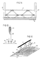
- each articulation 6 ′, 7 ′ has an axis which crosses a corresponding light 10 ′ arranged in said sub-arm rod (see also FIG. 12 for a perspective view).
- the two end diamonds 3 ′ are equipped with jacks 26, for example hydraulic, the cylinders of which are arranged in the base 1 opposite each other, parallel to said base and therefore parallel to the arm 2 and to the rod 10 'of the sub-arm.
- the rods 27 of the cylinders 26 are articulated by means of a roller 28 to a double link 29, itself articulated to one of the arms of the diamond close to the articulation 4 of the ground, the aforementioned references 27 to 29 being only indicated on one of the jacks 26 which equips one of the diamonds 3 'of FIG. 6 to avoid unnecessary repetitions.
- one of the articulations of the sub-arm of each rhombus in this case here the articulations 6 ′, are connected together by a bar link 30.
- the actuation of the jacks 26 makes it possible to act on one of the arms of the end diamonds and thus to cause the raising and lowering of the heddle 2 and of the sub-heald rod 10 ', the system can thus take, among other things, the positions shown in Figures 4 to 6, Figure 4 showing the folded position in which, as before, the assembly is housed in the base 1.
- the connecting bar 30 appeared very useful for ensuring a well parallel lifting of the heald and the sub-heald.
- the bar 30 stiffens the diamond 3 'of the medium without cylinder, because it is clear that it is not necessary to provide one cylinder per diamond and the arrangement shown with three diamonds and two cylinders is particularly interesting.
- the inventor also provided compression springs (not visible in the drawings) arranged in the openings 10'a, to ensure damping on the descent and / or to facilitate lifting.
- a counterweight 16 forces the sub-arm 10 "to be presented in such a way that the notches 14, 15 with which it is provided are turned towards said pawls 12, 13.
- FIG. 8 shows a barrier of the type of that of FIGS. 1 to 3 (one can of course use the same means or similar means for the embodiment of FIGS. 4 to 6), but the sub-stringer 10 is in several sections connected to each other by fittings, such as fitting 17, here of Cardan type.
- the rail 2 and / or the base 1 can also be in several parts (or in one and have elbows).
- Figure 9 already shows an application.
- Figures 10 to 13 show other possible applications.
- Figures 1 to 10 show a base 1 formed of an inverted T-shaped iron (Figure 10) or L-shaped ( Figure 9) and therefore constituting a plinth.
- Figures 11 to 15, on the other hand, show a U-shaped base 1.
- the base 1 in FIGS. 11 and 12 is intended to be placed in an excavation, or as here between two elements 19, 20 forming ramps, the barrier of FIG. 11 being of the type described in connection with FIGS. 1 to 3, and that of FIG. 12 of the type of that described in connection with FIGS. 4 to 6.
- the whole barrier can fold back into the base 1, the assembly forming, for example, a retarder (the arm 2 being sufficiently wide to cover the base 1).
- Figures 14 and 15 show a barrier as previously described, but which is further provided here with two lateral uprights 21 and 22 in which the ends of the heddle 2 are, for example, slidably mounted. It can be a barrier forming a portal, for example.
- An entirely interesting embodiment can of course be directly obtained with the embodiment of FIGS. 4 to 6, the sliding being ensured by the openings 10'a. To do this, simply add amounts in Figure 12.
- the base is mounted between two elements 19, 20 forming ramps.
- the base and the uprights 21 and 22 are articulated at 24, 25 with said elements respectively 19 and 20.
- the barrier In this way, if the barrier is forced with a vehicle in one direction or the other, the barrier will pivot towards the element opposite to the direction of arrival of the vehicle while the other element will be driven in rotation and will block the vehicle. from below.
- the articulation can only be provided on one side.
- the element intended to be raised can be equipped with a stand which unfolds at the time of pivoting to prevent its return to the initial position without special intervention.
Claims (19)
- Ausziehbare Barriere, wenigstens umfassend ein Geländer (2) und ein Untergeländer (10, 10', 10''), dadurch gekennzeichnet, daß das Geländer (2) durch wenigstens zwei Rhombengetriebe (3, 3') getragen wird, die im Abstand voneinander angeordnet sind und jeweils durch vier gelenkig an ihren Enden verbundene Arme gebildet werden, daß das Geländer (2) auf einer der Gelenkverbindungen jedes Rhombus, Geländer-Gelenkverbindung (5) genannt, befestigt ist, wobei die diametral gegenüberliegende Gelenkverbindung, Boden-Gelenkverbindung (4) genannt, zur Befestigung am Boden oder auf einem Element (1) zur Befestigung oder Aufstellung auf dem Boden bestimmt ist, wohingegen das Untergeländer durch wenigstens eine sich parallel zu dem Geländer erstreckende Stange (10, 10', 10'') gebildet wird, die die beiden anderen Gelenkverbindungen (6, 7; 6', 7'; 6'', 7''), Untergeländer-Gelenkverbindungen genannt, jedes Rhombus kreuzt oder von diesen gekreuzt wird, und daß wenigstens eine Einrichtung zur Arretierung der Barriere in wenigstens einer Gebrauchsstellung vorgesehen ist.
- Barriere nach Anspruch 1, dadurch gekennzeichnet, daß die Arretiereinrichtung auf wenigstens einer Untergeländer-Gelenkverbindung (6) für jeden Rhombus einen Gewindering (8) umfaßt, der mit einem Gewindebereich (10a) der Stange des Untergeländers (10) zusammenwirkt.
- Barriere nach Anspruch 2, dadurch gekennzeichnet, daß außerdem ein Drehantrieb (11) vorgesehen ist, der mit der Stange des Untergeländers (10) derart zusammenwirkt, daß deren Drehung das Auseinanderbewegen oder Aufeinanderzubewegen der Untergeländer-Gelenkverbindungen (6, 7) und umgekehrt das Aufeinanderzubewegen oder Auseinanderbewegen der Geländer-Gelenkverbindung (5) und der Boden-Gelenkverbindung (4) bewirkt.
- Barriere nach einem der Ansprüche 2 oder 3, dadurch gekennzeichnet, daß die Stange des Untergeländers (10) für jeden Rhombus einen Gewindebereich (10a) für eine einzige Untergeländer-Gelenkverbindung (6) des Rhombus und einen glatten Bereich (10b) für die jeweils andere Untergeländer-Gelenkverbindung (7) aufweist, die einen Ring (9) umfaßt, in welchem die Stange des Untergeländers frei verschieblich ist.
- Barriere nach Anspruch 1, dadurch gekennzeichnet, daß die Arretiereinrichtung für jeden Rhombus auf wenigstens einer der Untergeländer-Gelenkverbindungen (6'', 7'') eine Sperrklinke (12, 13) umfaßt, die zum Eingriff mit wenigstens einer Kerbe (14, 15) auf der Stange des Untergeländers (10'') bestimmt ist, wobei die Stange drehbar ist, um sich von der Sperrklinke durch einfache Drehung lösen zu können.
- Barriere nach Anspruch 5, dadurch gekennzeichnet, daß wenigstens ein Gegengewicht (16) vorgesehen ist, um die Stange (10'') des Untergeländers in einer Lage zu halten, in welche die Kerben (14, 15), mit welchen diese versehen ist, in Richtung der Sperrklinken gedreht werden.
- Barriere nach einem der Ansprüche 1 bis 6, dadurch gekennzeichnet, daß sie durch mehrere Elementarbarrieren gebildet wird, die untereinander durch Mittel (16') verbunden sind, die die Untergeländer (10'') einer beliebigen Drehung unterwerfen, wohingegen ein Mittel zur Verriegelung der Drehung an wenigstens einer der Elementarbarrieren vorgesehen sein kann.
- Barriere nach Anspruch 1, dadurch gekennzeichnet, daß die Arretiereinrichtung für wenigstens einige der Rhomben (3') einen doppelt wirkenden Hebemechanismus (26) umfaßt, dessen Stange (27) auf einen der Arme des betreffenden Rhombus (3') wirkt, wohingegen die Untergeländer-Gelenkverbindungen (6', 7') verschieblich an dem Untergeländer (10') befestigt sind, derart, daß die Betätigung des Hebemechanismus (26) das Auseinanderbewegen oder das Aufeinanderzubewegen der Untergeländer-Gelenkverbindungen (6', 7') und umgekehrt das Aufeinanderzubewegen oder Auseinanderbewegen der Geländer-Gelenkverbindungen (5) und der Boden-Gelenkverbindungen (4) bewirkt.
- Barriere nach Anspruch 8, dadurch gekennzeichnet, daß der Zylinder des Hebemechanismus in etwa auf Bodenniveau angeordnet ist und sich parallel zu dem Untergeländer (10') und dem Geländer (2) erstreckt, wohingegen die Stange (27) des Hebemechanismus durch wenigstens einen Schwenkarm (29) an einem an die Boden-Gelenkverbindung (4) angrenzenden Arm des betreffenden Rhombus angelenkt ist.
- Barriere nach Anspruch 9, dadurch gekennzeichnet, daß das abliegende Ende der Stange (27) des Hebemechanismus (26) über wenigstens eine zwischengeordnete Laufrolle (28) an dem Schwenkarm (29) angelenkt ist.
- Barriere nach einem der Ansprüche 8 bis 10, dadurch gekennzeichnet, daß eine (6') der beiden Gelenkverbindungen des Untergeländers (10') an wenigstens einiger der Rhomben (3') untereinander durch eine Verbindungsstange (30) verbunden sind.
- Barriere nach einem der Ansprüche 8 bis 11, dadurch gekennzeichnet, daß wenigstens einige der Untergeländer-Gelenkverbindungen (7') durch eine Druckfeder beaufschlagt sind, die als Mittel zur Dämpfung bei der Abwärtsbewegung dient.
- Barriere nach einem der Ansprüche 1 bis 12, dadurch gekennzeichnet, daß die Stange des Untergeländers mehrere Abschnitte aufweist, die untereinander über Gelenkverbinder (17) befestigt sind, die die Bildung einer Barriere in abgewinkelter Linie ermöglichen.
- Barriere nach einem der Ansprüche 1 bis 13, dadurch gekennzeichnet, daß die Boden-Gelenkverbindung (4) an einem Sockel (1) befestigt ist, der wenigstens eine Fußleiste zur Aufstellung oder Befestigung auf dem Boden bildet.
- Barriere nach Anspruch 14, dadurch gekennzeichnet, daß der Sockel (1) U-förmig ausgebildet ist.
- Barriere nach einem der Ansprüche 14 oder 15, dadurch gekennzeichnet, daß der Sockel (1) zur Anordnung in einer hierfür vorgesehenen Vertiefung bestimmt ist.
- Barriere nach Anspruch 16, dadurch gekennzeichnet, daß der Sockel (1) beiderseits seiner Länge nach durch Elemente (19, 20) eingefaßt ist, die eine Rampe bilden, und daß er an den Punkten (24, 25) an wenigstens eines dieser Elemente (19, 20) angelenkt ist, das derart auf dem Boden aufgestellt ist, daß sich das andere Element anhebt, wenn die Barriere gegen das schwenkbare Element gedrückt wird.
- Barriere nach einem der Ansprüche 1 bis 17, dadurch gekennzeichnet, daß die Enden des Geländers (2) verschieblich in zwei seitlichen Balken (21, 22) befestigt sind.
- Barriere nach Anspruch 18, dadurch gekennzeichnet, daß in wenigstens einem der Balken (21, 22) Mittel (23) zur Betätigung der Barriere bei Einwirkung auf das Geländer (2) vorgesehen sind.
Applications Claiming Priority (3)
| Application Number | Priority Date | Filing Date | Title |
|---|---|---|---|
| FR9214932 | 1992-12-11 | ||
| FR9214932A FR2699208B1 (fr) | 1992-12-11 | 1992-12-11 | Barrière extensible. |
| PCT/FR1993/001221 WO1994013885A1 (fr) | 1992-12-11 | 1993-12-10 | Barriere extensible |
Publications (2)
| Publication Number | Publication Date |
|---|---|
| EP0628111A1 EP0628111A1 (de) | 1994-12-14 |
| EP0628111B1 true EP0628111B1 (de) | 1997-09-10 |
Family
ID=9436469
Family Applications (1)
| Application Number | Title | Priority Date | Filing Date |
|---|---|---|---|
| EP94902012A Expired - Lifetime EP0628111B1 (de) | 1992-12-11 | 1993-12-10 | Ausziehbares Geländer |
Country Status (9)
| Country | Link |
|---|---|
| EP (1) | EP0628111B1 (de) |
| JP (1) | JPH07504006A (de) |
| AT (1) | ATE158042T1 (de) |
| AU (1) | AU5653794A (de) |
| BR (1) | BR9305869A (de) |
| CA (1) | CA2129529A1 (de) |
| DE (1) | DE69313834D1 (de) |
| FR (1) | FR2699208B1 (de) |
| WO (1) | WO1994013885A1 (de) |
Families Citing this family (22)
| Publication number | Priority date | Publication date | Assignee | Title |
|---|---|---|---|---|
| GB2274664B (en) * | 1993-01-28 | 1996-01-24 | Mckenzie Martin Limited | Improvements in or relating to safety barriers |
| JP3846971B2 (ja) * | 1997-05-22 | 2006-11-15 | 宮田自動機販売株式会社 | 車両出入口用フェンス |
| DE19723315C2 (de) * | 1997-06-04 | 2000-12-28 | Haeberlen Guenter | Durchlaßsperrvorrichtung |
| EP1757735A3 (de) * | 1998-05-26 | 2007-07-11 | General Dynamics Ordnance and Tactical Systems, Inc. | Nicht lethales, schnell entfaltetes Fahrzeugimmobilisationssystem |
| GB2349900B (en) * | 1999-05-13 | 2001-03-21 | Dennis Victor Cooke | Folding fence/barrier |
| WO2005098137A2 (en) * | 2004-03-31 | 2005-10-20 | Universal Safety Response, Inc. | Net and mat |
| ES2292283B1 (es) * | 2005-02-23 | 2009-02-01 | Jose Antonio Navarro Biota | Conjunto protector plegable para obras. |
| FR2886660B1 (fr) * | 2005-06-02 | 2007-09-07 | Somep Ind Soc Par Actions Simp | Garde corps relevable et support d'antenne de telecommunications mettant en oeuvre un tel garde corps |
| NL1031600C2 (nl) * | 2006-04-14 | 2007-10-16 | Altrex Bv | Uitklapbaar relingsamenstel voor een steiger, combinatie hiervan met een steiger, en gebruik van een uitklapbaar relingsamenstel. |
| FR2922243A1 (fr) * | 2007-10-11 | 2009-04-17 | Richard Lahaie | Dispositif de cloture escamotable |
| AT508699B1 (de) * | 2009-09-10 | 2011-06-15 | Wirrer Georg Mag | Hebetorsystem |
| MY163912A (en) * | 2010-02-11 | 2017-11-15 | Johnson & Nicholson M Sdn Bhd | Height adjustable speed bump |
| EP2418324B1 (de) * | 2010-07-22 | 2012-12-26 | Jörg P. Junker | Leitplankenanordnung |
| US9745762B2 (en) | 2014-11-26 | 2017-08-29 | Control Dynamics, Inc. | Vertically raising safety rail |
| US10724257B2 (en) | 2014-11-26 | 2020-07-28 | Control Dynamics, Inc. | Vertically raising safety rail with dual curtain assembly |
| CN104963553B (zh) * | 2015-07-14 | 2017-11-03 | 国电联合动力技术有限公司 | 一种电力安全围栏 |
| CN106988601A (zh) * | 2017-04-28 | 2017-07-28 | 国网山东省电力公司临朐县供电公司 | 开关柜专用遮拦网支架 |
| IT201700111952A1 (it) * | 2017-10-05 | 2019-04-05 | Faac Spa | Dispositivo dissuasore. |
| CN108103985A (zh) * | 2017-12-23 | 2018-06-01 | 郭舒洋 | 一种防暴车挡装置 |
| CN110043112B (zh) * | 2019-04-22 | 2020-10-23 | 嘉兴考普诺机械科技有限公司 | 一种铁路道口的提前预警双电网检测铁路栅栏 |
| JP6703680B1 (ja) * | 2019-04-24 | 2020-06-03 | 株式会社エム・システム技研 | 警告装置 |
| KR102607286B1 (ko) * | 2023-07-31 | 2023-11-29 | (주)세진에프에이 | 높낮이 조절되는 펜스 |
Family Cites Families (7)
| Publication number | Priority date | Publication date | Assignee | Title |
|---|---|---|---|---|
| US1595164A (en) * | 1925-08-08 | 1926-08-10 | Charles F Mundy | Door-jamb setter |
| FR1191803A (fr) * | 1958-02-21 | 1959-10-22 | Jaquemet & Mesnet Ets | Grille articulée repliable |
| FR1314328A (fr) * | 1962-02-09 | 1963-01-04 | Grille de sécurité pour fenêtres et portes | |
| CH437735A (fr) * | 1966-03-04 | 1967-06-15 | Nayagam Suzanne | Dispositif de coffrage |
| AT322192B (de) * | 1973-07-13 | 1975-05-12 | Aichinger Franz | Vorrichtung zum aussparen von öffnungen, insbesondere türöffnungen, in einem mauerwerk |
| FR2566453B1 (fr) * | 1984-06-26 | 1988-04-29 | Fichet Bauche | Grille extensible pour la protection d'une baie |
| FR2661932A1 (fr) * | 1990-05-11 | 1991-11-15 | Anglade Rene | Garde-corps repliable. |
-
1992
- 1992-12-11 FR FR9214932A patent/FR2699208B1/fr not_active Expired - Fee Related
-
1993
- 1993-12-10 WO PCT/FR1993/001221 patent/WO1994013885A1/fr active IP Right Grant
- 1993-12-10 AT AT94902012T patent/ATE158042T1/de not_active IP Right Cessation
- 1993-12-10 EP EP94902012A patent/EP0628111B1/de not_active Expired - Lifetime
- 1993-12-10 DE DE69313834T patent/DE69313834D1/de not_active Expired - Lifetime
- 1993-12-10 CA CA002129529A patent/CA2129529A1/fr not_active Abandoned
- 1993-12-10 JP JP6513872A patent/JPH07504006A/ja active Pending
- 1993-12-10 AU AU56537/94A patent/AU5653794A/en not_active Abandoned
- 1993-12-10 BR BR9305869A patent/BR9305869A/pt unknown
Also Published As
| Publication number | Publication date |
|---|---|
| FR2699208B1 (fr) | 1995-03-24 |
| FR2699208A1 (fr) | 1994-06-17 |
| AU5653794A (en) | 1994-07-04 |
| ATE158042T1 (de) | 1997-09-15 |
| JPH07504006A (ja) | 1995-04-27 |
| EP0628111A1 (de) | 1994-12-14 |
| DE69313834D1 (de) | 1997-10-16 |
| WO1994013885A1 (fr) | 1994-06-23 |
| CA2129529A1 (fr) | 1994-06-23 |
| BR9305869A (pt) | 1997-08-19 |
Similar Documents
| Publication | Publication Date | Title |
|---|---|---|
| EP0628111B1 (de) | Ausziehbares Geländer | |
| CA2312411C (fr) | Dispositif d'interruption de terre-plein central | |
| FR2897624A1 (fr) | Systeme de trappe d'acces automatisee avec garde-corps escamotable | |
| FR2624173A1 (fr) | Echafaudage grimpant a plate-forme constituant un tout unitaire | |
| FR2605619A1 (fr) | Engin repliable pour la manutention et le levage des charges | |
| FR2775992A1 (fr) | Dispositif de borne de voirie escamotable verticalement dans le sol | |
| FR2661932A1 (fr) | Garde-corps repliable. | |
| FR2889223A1 (fr) | Structure de travail en encorbeillement | |
| FR2863291A1 (fr) | Garde-corps pour plate-forme de coffrage et element de plate-forme avec garde-corps | |
| WO1992014674A1 (fr) | Dispositif d'ecartement ou de levage | |
| FR2604469A1 (fr) | Dispositif d'accrochage pour passerelle ou echafaudage de facade | |
| EP1091046B1 (de) | Verschlussvorrichtung für einen Kontroll- oder Inspektionsschacht | |
| EP1334236B1 (de) | Ausziehbare Barriere auf Rollen mit manuell auszieh- und einziehbaren Schwenkelementen | |
| EP0870725B1 (de) | Teleskopische Leiter und bewegliches Element geführt auf diese Leiter für einen Turmkran | |
| FR3044700A1 (fr) | Dispositif de fermeture | |
| EP0258919B1 (de) | Vorrichtung, die es ermöglicht, in einem Gebäude Zugang zu einem mit einer Luke verschlossenen Ausgang zu verleihen | |
| FR2520788A1 (fr) | Barriere-ecluse de securite pour plate-forme | |
| FR2817902A1 (fr) | Dispositif de condamnation securisee de l'acces a une echelle a crinoline | |
| FR2937026A1 (fr) | Dispositif elevateur et procede de fabrication correspondant | |
| FR2886660A1 (fr) | Garde corps relevable et support d'antenne de telecommunications mettant en oeuvre un tel garde corps | |
| FR2599422A1 (fr) | Echelle a coulisse pour chambre a cheminee d'acces central. | |
| FR2750148A1 (fr) | Dispositif permettant de creer une ouverture dans une file de dispositifs de retenue | |
| FR2932512A1 (fr) | Entretoise articulee pour plateforme support de banche | |
| BE526897A (de) | ||
| FR2799894A1 (fr) | Borne de distribution retractable |
Legal Events
| Date | Code | Title | Description |
|---|---|---|---|
| PUAI | Public reference made under article 153(3) epc to a published international application that has entered the european phase |
Free format text: ORIGINAL CODE: 0009012 |
|
| AK | Designated contracting states |
Kind code of ref document: A1 Designated state(s): AT BE CH DE DK ES FR GB GR IE IT LI LU MC NL PT SE |
|
| 17P | Request for examination filed |
Effective date: 19941222 |
|
| GRAG | Despatch of communication of intention to grant |
Free format text: ORIGINAL CODE: EPIDOS AGRA |
|
| 17Q | First examination report despatched |
Effective date: 19960201 |
|
| GRAH | Despatch of communication of intention to grant a patent |
Free format text: ORIGINAL CODE: EPIDOS IGRA |
|
| GRAH | Despatch of communication of intention to grant a patent |
Free format text: ORIGINAL CODE: EPIDOS IGRA |
|
| GRAA | (expected) grant |
Free format text: ORIGINAL CODE: 0009210 |
|
| AK | Designated contracting states |
Kind code of ref document: B1 Designated state(s): AT BE CH DE DK ES FR GB GR IE IT LI LU MC NL PT SE |
|
| PG25 | Lapsed in a contracting state [announced via postgrant information from national office to epo] |
Ref country code: NL Free format text: LAPSE BECAUSE OF FAILURE TO SUBMIT A TRANSLATION OF THE DESCRIPTION OR TO PAY THE FEE WITHIN THE PRESCRIBED TIME-LIMIT Effective date: 19970910 Ref country code: IT Free format text: LAPSE BECAUSE OF FAILURE TO SUBMIT A TRANSLATION OF THE DESCRIPTION OR TO PAY THE FEE WITHIN THE PRE;WARNING: LAPSES OF ITALIAN PATENTS WITH EFFECTIVE DATE BEFORE 2007 MAY HAVE OCCURRED AT ANY TIME BEFORE 2007. THE CORRECT EFFECTIVE DATE MAY BE DIFFERENT FROM THE ONE RECORDED.SCRIBED TIME-LIMIT Effective date: 19970910 Ref country code: GR Free format text: LAPSE BECAUSE OF FAILURE TO SUBMIT A TRANSLATION OF THE DESCRIPTION OR TO PAY THE FEE WITHIN THE PRESCRIBED TIME-LIMIT Effective date: 19970910 Ref country code: GB Free format text: LAPSE BECAUSE OF FAILURE TO SUBMIT A TRANSLATION OF THE DESCRIPTION OR TO PAY THE FEE WITHIN THE PRESCRIBED TIME-LIMIT Effective date: 19970910 Ref country code: ES Free format text: THE PATENT HAS BEEN ANNULLED BY A DECISION OF A NATIONAL AUTHORITY Effective date: 19970910 Ref country code: DK Free format text: LAPSE BECAUSE OF NON-PAYMENT OF DUE FEES Effective date: 19970910 Ref country code: AT Effective date: 19970910 |
|
| REF | Corresponds to: |
Ref document number: 158042 Country of ref document: AT Date of ref document: 19970915 Kind code of ref document: T |
|
| REG | Reference to a national code |
Ref country code: CH Ref legal event code: EP |
|
| REF | Corresponds to: |
Ref document number: 69313834 Country of ref document: DE Date of ref document: 19971016 |
|
| PG25 | Lapsed in a contracting state [announced via postgrant information from national office to epo] |
Ref country code: SE Effective date: 19971210 Ref country code: PT Effective date: 19971210 Ref country code: LU Free format text: LAPSE BECAUSE OF NON-PAYMENT OF DUE FEES Effective date: 19971210 |
|
| PG25 | Lapsed in a contracting state [announced via postgrant information from national office to epo] |
Ref country code: DE Free format text: LAPSE BECAUSE OF FAILURE TO SUBMIT A TRANSLATION OF THE DESCRIPTION OR TO PAY THE FEE WITHIN THE PRESCRIBED TIME-LIMIT Effective date: 19971211 |
|
| PG25 | Lapsed in a contracting state [announced via postgrant information from national office to epo] |
Ref country code: LI Free format text: LAPSE BECAUSE OF NON-PAYMENT OF DUE FEES Effective date: 19971231 Ref country code: CH Free format text: LAPSE BECAUSE OF NON-PAYMENT OF DUE FEES Effective date: 19971231 Ref country code: BE Free format text: LAPSE BECAUSE OF NON-PAYMENT OF DUE FEES Effective date: 19971231 |
|
| REG | Reference to a national code |
Ref country code: IE Ref legal event code: FG4D Free format text: 76381 |
|
| NLV1 | Nl: lapsed or annulled due to failure to fulfill the requirements of art. 29p and 29m of the patents act | ||
| GBV | Gb: ep patent (uk) treated as always having been void in accordance with gb section 77(7)/1977 [no translation filed] |
Effective date: 19970910 |
|
| PG25 | Lapsed in a contracting state [announced via postgrant information from national office to epo] |
Ref country code: IE Free format text: LAPSE BECAUSE OF NON-PAYMENT OF DUE FEES Effective date: 19980605 |
|
| BERE | Be: lapsed |
Owner name: ANGLADE RENE Effective date: 19971231 |
|
| PG25 | Lapsed in a contracting state [announced via postgrant information from national office to epo] |
Ref country code: MC Free format text: LAPSE BECAUSE OF NON-PAYMENT OF DUE FEES Effective date: 19980630 |
|
| REG | Reference to a national code |
Ref country code: IE Ref legal event code: FD4D Ref document number: 76381 Country of ref document: IE |
|
| PLBE | No opposition filed within time limit |
Free format text: ORIGINAL CODE: 0009261 |
|
| STAA | Information on the status of an ep patent application or granted ep patent |
Free format text: STATUS: NO OPPOSITION FILED WITHIN TIME LIMIT |
|
| REG | Reference to a national code |
Ref country code: CH Ref legal event code: PL |
|
| 26N | No opposition filed | ||
| PGFP | Annual fee paid to national office [announced via postgrant information from national office to epo] |
Ref country code: FR Payment date: 20010628 Year of fee payment: 8 |
|
| PG25 | Lapsed in a contracting state [announced via postgrant information from national office to epo] |
Ref country code: FR Free format text: LAPSE BECAUSE OF NON-PAYMENT OF DUE FEES Effective date: 20020830 |
|
| REG | Reference to a national code |
Ref country code: FR Ref legal event code: ST |