EP0626312A2 - Vakkuumverpackung, Verfahren und Vorrichtung zur Herstellung einer solchen mit körnigem Material gefüllten Verpackung - Google Patents
Vakkuumverpackung, Verfahren und Vorrichtung zur Herstellung einer solchen mit körnigem Material gefüllten Verpackung Download PDFInfo
- Publication number
- EP0626312A2 EP0626312A2 EP94200374A EP94200374A EP0626312A2 EP 0626312 A2 EP0626312 A2 EP 0626312A2 EP 94200374 A EP94200374 A EP 94200374A EP 94200374 A EP94200374 A EP 94200374A EP 0626312 A2 EP0626312 A2 EP 0626312A2
- Authority
- EP
- European Patent Office
- Prior art keywords
- package
- vacuum
- packaging material
- sheet
- suction opening
- Prior art date
- Legal status (The legal status is an assumption and is not a legal conclusion. Google has not performed a legal analysis and makes no representation as to the accuracy of the status listed.)
- Granted
Links
Images


Classifications
-
- B—PERFORMING OPERATIONS; TRANSPORTING
- B65—CONVEYING; PACKING; STORING; HANDLING THIN OR FILAMENTARY MATERIAL
- B65B—MACHINES, APPARATUS OR DEVICES FOR, OR METHODS OF, PACKAGING ARTICLES OR MATERIALS; UNPACKING
- B65B31/00—Packaging articles or materials under special atmospheric or gaseous conditions; Adding propellants to aerosol containers
- B65B31/04—Evacuating, pressurising or gasifying filled containers or wrappers by means of nozzles through which air or other gas, e.g. an inert gas, is withdrawn or supplied
- B65B31/08—Evacuating, pressurising or gasifying filled containers or wrappers by means of nozzles through which air or other gas, e.g. an inert gas, is withdrawn or supplied the nozzle being adapted to pierce the container or wrapper
-
- B—PERFORMING OPERATIONS; TRANSPORTING
- B65—CONVEYING; PACKING; STORING; HANDLING THIN OR FILAMENTARY MATERIAL
- B65D—CONTAINERS FOR STORAGE OR TRANSPORT OF ARTICLES OR MATERIALS, e.g. BAGS, BARRELS, BOTTLES, BOXES, CANS, CARTONS, CRATES, DRUMS, JARS, TANKS, HOPPERS, FORWARDING CONTAINERS; ACCESSORIES, CLOSURES, OR FITTINGS THEREFOR; PACKAGING ELEMENTS; PACKAGES
- B65D81/00—Containers, packaging elements, or packages, for contents presenting particular transport or storage problems, or adapted to be used for non-packaging purposes after removal of contents
- B65D81/18—Containers, packaging elements, or packages, for contents presenting particular transport or storage problems, or adapted to be used for non-packaging purposes after removal of contents providing specific environment for contents, e.g. temperature above or below ambient
- B65D81/20—Containers, packaging elements, or packages, for contents presenting particular transport or storage problems, or adapted to be used for non-packaging purposes after removal of contents providing specific environment for contents, e.g. temperature above or below ambient under vacuum or superatmospheric pressure, or in a special atmosphere, e.g. of inert gas
- B65D81/2007—Containers, packaging elements, or packages, for contents presenting particular transport or storage problems, or adapted to be used for non-packaging purposes after removal of contents providing specific environment for contents, e.g. temperature above or below ambient under vacuum or superatmospheric pressure, or in a special atmosphere, e.g. of inert gas under vacuum
- B65D81/2038—Containers, packaging elements, or packages, for contents presenting particular transport or storage problems, or adapted to be used for non-packaging purposes after removal of contents providing specific environment for contents, e.g. temperature above or below ambient under vacuum or superatmospheric pressure, or in a special atmosphere, e.g. of inert gas under vacuum with means for establishing or improving vacuum
Definitions
- This invention relates to a method for making a vacuum package filled with granular product, in which a package made from a flexible packaging material and filled with a granular product is evacuated and sealed hermetically.
- the volume of the vacuum chamber be kept as small as possible. Accordingly, the volume of the package to be evacuated is preferably made as small as possible by already folding up the filled package as much as possible before it is placed in the vacuum chamber. Moreover, in that case it is not necessary to arrange folding means in the vacuum chamber. In that case, the vacuum chamber need only contain the welding jaws which are necessary to hermetically seal the package which is already folded up completely. This means that the package is evacuated through a narrow gap left open in the top of the package. While the package is being evacuated in a short time, a high outflow velocity of gasses to be removed from the package arises in the gap.
- the object of the present invention is to improve the above-mentioned known method, and to that end provides a method for making a vacuum package filled with granular product, in which a package produced from a flexible packaging material and filled with a granular product is evacuated and sealed hermetically, characterised in that the package, before being evacuated, is compressed by applying pressure to the sidewalls of the package, so that the granular product forms a compact whole, that subsequently a vacuum element is connected to a suction opening provided in a wall of the package, this vacuum element evacuating the package without the package being otherwise externally subjected to vacuum, and that after the evacuation the suction opening is sealed hermetically.
- the package before being evacuated, is brought under an external pressure compressing the package such that the granular filling becomes a compact whole, i.e. the granules are no longer loosely moveable relative to each other.
- the granules can no longer be sucked from the package.
- the suction opening in the package not until after the hermetic sealing thereof, for instance at evacuation.
- the suction opening if so desired, can be provided in the yet unfilled package, in particular when measures have been taken to prevent egress of the still loose granular material from the filled package, for instance by providing a welding strip, to be discussed hereinafter, under the suction opening. Since the suction opening need only be a small hole, the certainty that the package will not leak at the sealed opening is greater than in the case of a relatively large seal over the full width of the package.
- An important further advantage of compressing the package is that thereby the free volume to be evacuated of the package between the granules is reduced to a large extent. As a consequence, and because it is no longer necessary to use a large vacuum chamber which is to accommodate the entire package as in the known method, a large saving of required vacuum capacity is obtained and moreover a very short evacuation time is possible. Only the suction opening is connected to a vacuum line, and the rest of the package remains in the atmospheric environment.
- the suction opening can be pierced in the package by a reciprocating needle mounted in the vacuum element.
- a reciprocating needle mounted in the vacuum element.
- the compression of the package can be implemented in various ways.
- a rigid, plate-shaped element is placed against each side wall of the package, which element is pressed against the package mechanically or otherwise.
- the plate-shaped elements can be movably interconnected, for instance by means of springing hinges, and may thereby form a shell enclosing the package relatively tightly.
- a bottom plate it is also possible for a bottom plate to be movably connected with the side plates so as to form a kind of holder into which the package fits.
- the package for the purpose of the compression, is placed in a bag-shaped body made from elastic material and of double-walled design.
- a bag-shaped body made from elastic material and of double-walled design.
- the two methods can also be combined, such that the plate-shaped elements or the holder formed therefrom are placed between the inner wall of the bag-shaped body and the exterior of the package and the plates are pressed against the package by inflating the bag.
- An additional advantage of compressing the package, which takes place when the filling is still loose and hence movable, is that the walls of the finished package acquire a smoother appearance than the relatively rough surface normally acquired by a vacuum package with granular contents.
- the package possesses a rectangular shape, preferably not only the sidewalls but also the top surface and the bottom surface are pressed towards each other.
- This can for instance be effected by arranging a supporting plate on the free end face of the package remote from the other end face proximal to the bottom of the bag-shaped body referred to. In that case, as the bag-shaped body is being inflated, the package is also compressed between the bottom of the bag and the supporting plate.
- a sealing strip may be provided under the suction opening, between the inside wall of the package and the filling.
- the sealing strip along the edges thereof, is fixedly connected to the inside wall of the package.
- openings Provided in the zone of the sealing strip and located between the edges thereof and the suction opening in the package are openings through which communication between the suction opening and the interior of the package continues to exist during evacuation.
- the sealing strip is sealed around the suction opening to the inside wall of the package in known manner, whereafter the vacuum element can be removed from the package and the package is entirely sealed hermetically.
- the welding element may for instance be formed by an annular welding jaw placed around the connection of the vacuum element. Because upon compression the filling forms a compact and hard whole, the filling can serve as a support for the sealing strip during sealing without requiring that the sealing strip on the inside of the package be supported with additional means.
- the suction opening can also be designed as the opening of a non-return valve provided in the wall of the package, permitting outflow of air from the package and blocking inflow of air into the package. If desired, after evacuation, on the exterior of the package a sealing strip can be welded or an adhesive strip can be fitted over the suction opening to provide additional protection against leakage.
- the suction opening used is the narrow gap formed between two portions of the packaging film folded onto each other, for instance the gap-shaped opening formed between film portions when portions of the sidewalls of the package located above the filling are folded over onto each other, as is required for forming the top face of the package.
- the gap is sealed.
- the film at least at the location of the gap, may be provided with a firmly sealable coating layer which, upon the above-mentioned folding over of the film, comes to be located between the two film portions located on each other.
- electrically heated welding jaws which are pressed onto the folded portion of the film adjacent the gap, the two superposed film portions are welded together whereby the package is entirely sealed hermetically.
- the volume to be evacuated is considerably smaller than in the case of a non-compacted package, and the residual gasses can be sucked from the package at a high velocity without the granules being entrained from the package, the evacuation can be implemented in a short time, for instance in just two seconds in the case of a 250 gram package of ground coffee, as opposed to approximately 12 seconds previously. Also, the energy required for evacuation is drastically reduced. For instance, instead of an 18 kW vacuum pump, a 1 kW vacuum pump can be sufficient.
- a further object of the present invention is to provide a particular embodiment of the method, whereby portions on the package provided with informational characters remain properly legible for a human or electronic observer.
- the commonly known vacuum package upon evacuation generally a rough appearance is obtained, even if the package is made from a smooth sheet of packaging material, owing to the fact that the thin-walled packaging material, such as paper or aluminium foil, is pressed against the granular contents of the package as a result of the difference in pressure between the atmospheric outside air and the vacuum in the package.
- the typically block-shaped and rectangular package is usually provided with printed text, figures, marks, a bar code, a date, manufacturing data and the like, which will be referred to hereinafter as informational characters.
- these informational characters are already provided on the packaging material supplied in the form of a sheet, before a package is folded from a sheet. Owing to the rough, bumpy structure of the surface of the packaging material in the finished package, the informational characters present are deformed and thereby rendered more difficult to read or poorly identifiable. If, for instance, the package is provided with a bar code which is to be read electronically, reading errors will occur as a result of the circumstance that the separate and closely spaced bars of varying thickness do not accurately maintain their relative position and lose their rectilinearity.
- these problems are obviated in that, at the location on the packaging material of the package where the informational characters are located, a reinforcement zone is provided between the packaging material and the granular product before the package is evacuated, so that at that point the roughness of the surface of the packaging material upon evacuation is reduced and the legibility of the informational characters is improved.
- the packaging material used is a little flexible and relatively thick singular or composite film which possesses a higher degree of natural stiffness and is therefore better resistant to deformation in the vacuum package.
- Yet another solution is to subject the package to an aftertreatment, whereby the unevennesses in the package are reduced or removed.
- the aftertreatment constitutes an additional process step which is preferably avoided in order to keep the production of the package as simple as possible.
- the package before being evacuated, is formed from at least two different sheets of packaging material, at least one basic sheet determining at least substantially the outward form of the package and at least one insert sheet being connected to the basic sheet adjacent its circumferential edges in a manner at least substantially non-overlapping with respect to the basic sheet.
- a package produced according to this method provides many advantages. Thus, it is for instance possible to fold the basic sheet into a shell having two open ends, to hermetically connect an edge of the basic sheet extending in the longitudinal direction of the shell to subjacent material of the basic sheet, to fold over a portion of the basic sheet adjacent a first open end of the shell and to hermetically connect the insert sheet to the folded-over portion of the basic sheet.
- the insert sheet forms, for instance, the bottom of the package.
- the package can subsequently be filled with the granular product through its second open end, whereafter the second open end is folded up and sealed hermetically, followed by evacuation of the package as discussed hereinabove.
- the second open end can be folded up and sealed hermetically according to a method which is known per se.
- the package is filled with the granular material through its second open end, whereafter a portion of the basic sheet is folded over adjacent the second open end of the shell and a second insert sheet is hermetically connected to the folded-over portion, followed by evacuation of the package as discussed hereinabove.
- a comparable film saving is realised at the top of the package as well.
- the basic and insert sheets are made of different types of packaging material or film. It has been found that a package having the insert bottom described is better adapted to stand open than a package with a conventional bottom. In this connection, it is then possible, for instance, to use a thinner film for the insert sheet than for the basic sheet.
- the present invention also encompasses an apparatus for making a vacuum package filled with a granular material, comprising a vacuum element for evacuating a package made from a flexible packaging material, such as for instance a film, and filled with granular material, and closing means for hermetically sealing the filled package, characterised in that the apparatus further comprises pressure means for applying pressure to at least the sidewalls of the closed package, so that the granular filling forms a compact whole, and that the vacuum element is adapted for connection to a suction opening, provided in a wall of the closed and compressed package, for evacuating the package not otherwise subjected to vacuum, and that the closing means are adapted for hermetically sealing the suction opening.
- the present invention further relates to a vacuum package made from a flexible packaging material, filled with a granular material and evacuated by a method according to the invention.
- the package is provided with a hermetically sealed suction opening. More particularly, the vacuum package is characterised in that, at the location on the packaging material where informational characters are located, a reinforcement zone is provided between the packaging material and the filling, so that at that point the roughness of the surface of the packaging material is reduced and the legibility of the informational characters is improved.
- the package is made up of at least two sheets of a film-like packaging material, of which at least one basic sheet determines at least substantially the outward form of the package and at least one insert sheet which is hermetically connected to the basic sheet adjacent its edges in a manner substantially non-overlapping at least with regard to the basic sheet.
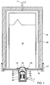
- Fig. 1 shows a rigid chamber 12, open at one end, arranged with the open end facing downward.
- a bag-shaped body in this case designed as a double-walled rubber bag 26.
- a compressed air line 11 for supplying compressed air to the interior of the bag and thereby inflating the bag.
- a supporting plate in this case cover 16
- a package 15 is placed within the bag with some clearance.
- the package 15 is made from a flexible packaging film, such as thermoplastic film or paper and is filled entirely with a granular product, for instance (fine-)ground coffee.
- the package is closed but not yet subjected to vacuum.
- the cover 16 is provided with a centrally located opening 31.
- a sealing strip 18 has been welded along the edges 29 to the inside wall of the package.
- the sealing strip is provided with a number of openings 19 located within the strip edges but off the centre (see also Fig. 3).
- the apparatus further comprises a vacuum element 21 adapted to be connected hermetically to the cover 16 over the opening 31 by means of a sealing ring 27.
- the interior of the vacuum element is connected to a line 23 which is connected with a vacuum pump.
- a welding element 24 which, at the end proximal to the opening 31 in the cover, is provided with an annular sealing jaw 22 which can be heated electrically.
- the welding element can reciprocate within the vacuum element, i.e. be moved toward the opening 31 and away from the opening 31.
- a needle 25 capable of reciprocating relative to the sealing jaw 22 through a central opening in the welding jaw by means of an electromagnet.
- the apparatus according to Fig. 1 is used as follows. First, the package 25, completely filled and hermetically sealed but not yet evacuated, is fitted into the bag 26 (or the chamber 12 with the bag 26 is fitted over the package) at this point, the cover 16 and the vacuum element 21 have not been arranged yet when the package is disposed in the bag, the cover 16 is placed on the chamber 12 and pressed hermetically against the edges of the chamber by means of the hinging clamps 17. Then a punch 28 (Fig. 2) is inserted through the opening in the cover. The punch 28 is moved up so far that the convex front end thereof presses the film at that location and also the sealing strip 18 located behind it in upward direction to a slight extent (Fig. 2). In this position the punch is fixed.
- the film 20 at the opening 31 is to a slight extent sucked towards the vacuum element, thereby moving away from the sealing strip. Owing to the openings 19 present in the sealing strip, no difference in pressure on either side of the sealing strip is produced, so that it retains the position assumed.
- the electromagnet operating the needle 25 is now activated, so that the needle is moved outwardly and pierces a hole in the film. In this process the needle does not touch the sealing strip 18. This is the situation as depicted in Fig. 1.
- the contents of the package are subjected to vacuum via the hole in the film serving as suction opening and through the openings 19 in the sealing strip.
- the sealing element is activated, pressing the film 20 and the sealing strip against each other and welding them together by means of the heated sealing jaw 22.
- the sealing strip is supported by the filling which has become hard as a result of the compression of the package and the vacuum. Because the film and sealing strip are welded together in a zone within the openings 19 in the welding strip, an airtight closure of the package is obtained at that location.
- the compressed air pressure on the bag is now removed, so that the bag shrinks again. If desired, at this point a vacuum source can be connected to the interior of the bag so that the bag shrinks to an even higher degree and the package can more readily be removed from the bag.
- the vacuum element can now be removed from the cover and likewise the cover can be removed from the chamber.
- the package now finished is removed from the bag and replaced with a next package to be evacuated. It is observed that during the entire evacuation process the exterior of the package, with the sole exception of the small area opposite the opening 31 in the cover, is not subjected to vacuum and remains in an atmospheric environment.
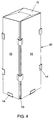
- a holder 30 (Fig. 4) is placed in the bag.
- the holder is made up of four metal side plates 10 and a metal bottom plate 13.
- the plates 10 and 13 are interconnected through springing hinges 14. The hinges allow a slight back-and-forth movement of the plates.
- the holder is placed in the bag, with the bottom plate upwards against the bottom of the bag.
- the package is fitted into the holder before or after the holder has been arranged in the bag. As the bag is being inflated, it presses the plates 10, 13 against the package, so that the package is compressed. Inserting and removing the package into or from the holder 30 is normally easier than in the case where the package is placed directly into the bag 26.
- Fig. 5 shows a possible embodiment of the vacuum package 15, in this case blocked-shaped and rectangular, filled with, for instance, 215 g coffee beans or ground coffee and under a reduced pressure of, for instance, 100 mbar.
- the package 15 is made from, for instance, at least one thin-walled sheet of smooth synthetic film and evacuated by means of the apparatus of Fig. 1.
- the package 15 generally shows roundabout a rough surface 41 because the packaging material is pressed against the granular contents by the outside air. An exception to the rough surface is formed by a rectangular portion 52 which has remained smooth and where characters are provided on the packaging material.
- a plate-shaped element here formed by a cardboard card 43 of corresponding dimensions to those of the portion 42, is located between the smooth portion 42 and filling of the package.
- the presence of the card 43 prevents the package acquiring a rough surface at the location of the card.
- the card need only extend under the area on the package that comprises the informational characters. If so desired, for practical reasons, the card may extend to a greater or lesser extent beyond the zone with informational characters as well. For instance to prevent displacement of the card during or after the filling of the still open package, the card may extend in lateral direction from the left-hand sideline to the right-hand sideline of a wall. If an entire wall is provided with text, the plate-shaped element may extend over the entire wall. Preferably, however, the plate-shaped element should not extend beyond the sideline mentioned into an adjacent wall, nor should the single element extend over three or more walls. If two or more walls of the package are provided with informational characters, each wall may be provided with a separate plate-shaped element. In general, for economic reasons, it is desired that the card or other plate-shaped element be not made much larger than the portion of the wall or walls of the package that is provided with informational characters.
- the loose card Before the package is closed and vacuumized, the loose card can be slipped into the package during or after the filling thereof. It is also possible for the card to be adhered to the as yet unfolded flat sheet of packaging material at the required points beforehand.
- the card can be made from cardboard as well as any other material suitable for the purpose, for instance thin-walled metal or plastics.
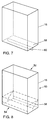
- Fig. 7 shows a first possible embodiment of a package 15 which is not finished yet, i.e. it has not yet been evacuated and sealed hermetically by means of the apparatus of Fig. 1.
- the package 5 of Fig. 7 consists of a flexible packaging film in the form of a shell 50.
- Fig. 8 shows the open shell 50 with two open ends 52, 54, from which the as yet unfinished package of Fig. 7 is produced, i.e. before a bottom is arranged in the package.
- fold lines 56 are indicated by broken lines, along which a part of the shell 50 can be folded for obtaining a bottom 58 of the package 15.
- Fig. 7 shows the bottom 58 which has been obtained by folding the shell 50 along the fold lines 56.
- the bottom 58 can be rendered properly airtight by sealing the upright edge 60 of the shell 50 with closing means which are known per se, such as, for instance, a welding device. Thereafter the package 15 can be filled, closed and evacuated as described hereinbefore.
- the closure of the open end 52 at the top of the package 15 can of course be implemented entirely analogously to the manner in which the open end 54 is closed.
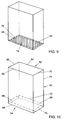
- a second embodiment of the package 15 will now be discussed, which comprises a bottom 62 which is particularly advantageous in accordance with the invention. Parts corresponding with those in Figs. 7 and 8 have been given the same reference numerals.
- Fig. 10 shows the open shell 50 with two open ends 52, 54 from which the as yet unfinished package of Fig. 9 is produced, i.e. before a bottom is provided in the package.
- Four edges 64-70 have been folded inwards along fold lines 72 indicated by broken lines in Fig. 10.
- Fig. 10 shows the edges 64-70 in unfolded condition and Fig. 9 shows them in inwardly folded condition.
- the package 15 of Fig. 9 further shows an insert sheet 74 which, adjacent its circumferential edges 75 indicated by broken lines in Fig. 9, is airtightly connected to the edges 64-70 of the shell 50.
- the insert sheet 74 is hatched.
- Fig. 9 the insert sheet 74 is hatched.
- the insert sheet 74 is connected on the inside of the package to the edges 64-70 of the shell 50, but it may also be airtightly connected on the outside of the shell 50 to the edges 64-70.
- the attachment can be implemented airtightly again in a manner which is known per se using, for instance, a welding device.
- the insert sheet 74 can be provided both on the inside and on the outside of the edges 64-70. This distinction is not depicted in Fig. 9.
- the open end 52 at the top of the package can be closed as discussed with reference to the package shown in Fig. 7.
- the insert sheet will preferably be attached on the outside of the edges adjacent the open end 52 (not shown in Fig. 9).
- the filling of the package 15 can offer sufficient resistance for the insert sheet in question to be pressed firmly against the edges when it is being attached to the edges using, for instance, a welding device.
- Figs. 11 and 12 show a third embodiment of the package 15, parts corresponding with Figs. 7 and 8 being indicated by the same reference numerals.
- Fig. 12 shows the open shell 50 with two open ends 52, 54, from which the as yet unfinished package of Fig. 11 can be produced.
- Fig. 12 shows the edges 64-70 in unfolded condition, the fold lines 72 being indicated by broken lines.
- the shell 50 further comprises two cuts 76, depicted in bold type, enabling the edge 70 to be folded outwards.
- the top of the package is provided with an insert sheet 74 which is airtightly connected to the outside of the edges 64-68 and the inside of the edge 70.
- the width d1 of the edge 70 is greater than the width d2 of the other edges 64-68.
- the insert sheet 74 is only connected to the edge 70 at its edges, as indicated in Fig. 11 by means of broken line 76. This enables the package to be readily opened, for instance by cutting off the edge 70 and the insert sheet 74 along the line C.
- the width d1 can also be chosen to be equal to the width d2.
- the bottom of the package according to Fig. 11 may be provided with an insert sheet as discussed with respect to the top of the package. It is also possible, however, for the bottom to be provided with an insert sheet as shown in Figs. 9 and 11, respectively.
- the bottom 54 of the package according to Fig. 11 can also be formed from the shell 50 in the manner of the bottom of the package 15 discussed with reference to Fig. 7.
- the shell 50 may further be provided with an opening 78 depicted as a broken line. Adjacent the edges of the opening, an insert sheet 80 has been airtightly connected to the shell 50, for instance with the aid of a welding device.
- the insert sheet in question may beforehand have been provided with characters or pictures, so that they can be of a predetermined desired quality.
- the insert sheet 80 it is possible for the insert sheet 80 to be made of a different material from the shell 50.
- the insert sheet may for instance be made of a less flexible film than the shell 50.
- the insert sheet 80 will then have a less rough surface than the rest of the package. Any pictures and characters on the insert sheet 80 will then be better visible.
- a package 15 with an insert sheet 74, 80 that the insert sheet can be made from the same material as or a different material from the shell 50.
- the packages 15 described hereinbefore are all preferably evacuated as discussed hereinabove.
- the insert sheet 74, 80 may be provided, for instance in the centre thereof, with a welding strip 18, so that evacuation of the finished package can be implemented by means of the apparatus according to Fig. 1.
- a hole has been pierced in the insert sheet beforehand for evacuating the package, whereafter the hole is sealed by providing a welding strip over the hole.
- both the hole and the welding strip can be provided in the insert sheet beforehand, and the welding strip may be located both inside and outside the finished package.
- the hole may also be provided at a position where insert sheet 74 and an edge 64-70 of the shell 50 are attached to each other.
- the hole can be sealed, for instance by heating the location referred to (again), so that the insert sheet and/or shell 50 will at least partly melt, fuse or deliquesce again at that location and the hole will be sealed.
Applications Claiming Priority (4)
| Application Number | Priority Date | Filing Date | Title |
|---|---|---|---|
| NL9300754A NL9300754A (nl) | 1993-05-04 | 1993-05-04 | Werkwijze en inrichting voor het vervaardigen van een met korrelig materiaal gevuld vacuümpak. |
| NL9300754 | 1993-05-04 | ||
| NL9400194 | 1994-02-07 | ||
| NL9400194A NL9400194A (nl) | 1994-02-07 | 1994-02-07 | Vacuümpak gevuld met een korrelig produkt en werkwijze voor het vervaardigen van een dergelijk vacuümpak. |
Publications (3)
| Publication Number | Publication Date |
|---|---|
| EP0626312A2 true EP0626312A2 (de) | 1994-11-30 |
| EP0626312A3 EP0626312A3 (de) | 1995-01-18 |
| EP0626312B1 EP0626312B1 (de) | 1998-06-17 |
Family
ID=26647092
Family Applications (1)
| Application Number | Title | Priority Date | Filing Date |
|---|---|---|---|
| EP94200374A Expired - Lifetime EP0626312B1 (de) | 1993-05-04 | 1994-02-11 | Verfahren und Vorrichtung zur Herstellung einer mit körnigem Material gefüllten Vakkuumverpackung |
Country Status (8)
| Country | Link |
|---|---|
| US (1) | US5598684A (de) |
| EP (1) | EP0626312B1 (de) |
| JP (1) | JPH07309308A (de) |
| AT (1) | ATE167444T1 (de) |
| CA (1) | CA2115635A1 (de) |
| DE (1) | DE69411080T2 (de) |
| DK (1) | DK0626312T3 (de) |
| ES (1) | ES2121140T3 (de) |
Cited By (6)
| Publication number | Priority date | Publication date | Assignee | Title |
|---|---|---|---|---|
| EP1057729A1 (de) | 1996-09-17 | 2000-12-06 | Molins Plc | Vorrichtung und Verfahren zum Herstellen von gesiegelten Verpackungen |
| WO2008022815A1 (en) | 2006-08-25 | 2008-02-28 | Interprise Brussels S.A. | Method and assembly for the controlled change of the gas content inside a package |
| WO2016066990A1 (en) * | 2014-10-31 | 2016-05-06 | British American Tobacco (Investments) Limited | Apparatus and method for manufacturing a smoking article pack |
| EP3208066A1 (de) * | 2016-02-17 | 2017-08-23 | NGP Next Generation Pallets GmbH | Verfahren und herstellungsvorrichtung zur herstellung eines laminierten objekts, laminierte objekte, verfahren zur herstellung von paletten sowie paletten |
| CN109068895A (zh) * | 2016-03-13 | 2018-12-21 | 福乐士吉科有限公司 | 真空容器、系统和方法 |
| CN112173232A (zh) * | 2020-10-25 | 2021-01-05 | 刘俊君 | 一种智能车载压缩机 |
Families Citing this family (16)
| Publication number | Priority date | Publication date | Assignee | Title |
|---|---|---|---|---|
| US6013905A (en) * | 1998-04-30 | 2000-01-11 | Oster; Eugene L. | Magnetic vacuum oven with safe door access to air gap |
| ATE262445T1 (de) * | 1999-12-15 | 2004-04-15 | Kellog Co | Transportbehälter für schüttgut und verfahren zur seiner herstellung |
| ATE303948T1 (de) | 2000-03-02 | 2005-09-15 | Tempra Tech Inc | Hilfe beim vakuumverpacken |
| US20040026292A1 (en) * | 2000-12-15 | 2004-02-12 | Ours David C. | Transportable container for bulk goods and method for forming the container |
| US6945015B2 (en) * | 2003-12-10 | 2005-09-20 | Kellogg Company | Shrink wrap transportable container and method |
| US6892768B1 (en) | 2003-12-10 | 2005-05-17 | Kellogg Company | Stretch wrap transportable container and method |
| US7536840B2 (en) * | 2005-02-18 | 2009-05-26 | Kellogg Company | Stackable bulk transport container |
| US7377087B2 (en) * | 2005-08-19 | 2008-05-27 | Sunbeam Products. Inc. | Method of preserving foodstuffs |
| DE102006010772B4 (de) * | 2006-03-08 | 2009-04-23 | Thermozell Entwicklungs- Und Vertriebs Ges.M.B.H. | Mit Polystyrolgranulat befülltes Gebinde sowie Vorrichtung und Verfahren zur Herstellung des Gebindes |
| US20090238498A1 (en) * | 2008-03-18 | 2009-09-24 | Kevin Lin | Compaction Package |
| SG193835A1 (en) | 2008-06-05 | 2013-10-30 | Kellog Co | Unitary transporter base and shaper and slip frame former for forming a transportable container |
| MX2010013339A (es) | 2008-06-11 | 2010-12-22 | Kellog Co | Metodo para el llenado y formacion de un contenedor transportable para articulos a granel. |
| JP5566387B2 (ja) * | 2008-09-03 | 2014-08-06 | ケロッグ カンパニー | ばら積み品のための運搬可能容器の形成方法 |
| US9623622B2 (en) | 2010-02-24 | 2017-04-18 | Michael Baines | Packaging materials and methods |
| SG190181A1 (en) | 2010-12-01 | 2013-06-28 | Kellog Co | Transportable container for bulk goods and method for forming the same |
| KR101036023B1 (ko) * | 2011-01-05 | 2011-05-19 | 황창성 | 방사성폐기물 수거장치 및 방법 |
Citations (2)
| Publication number | Priority date | Publication date | Assignee | Title |
|---|---|---|---|---|
| US3382642A (en) * | 1965-10-14 | 1968-05-14 | Continental Can Co | Method of filling pouches |
| DE2034033A1 (de) * | 1969-07-19 | 1971-03-25 | S r 1 Centro Cesare Cassina, Mai land (Italien) | Verfahren zum Verpacken bei reduziertem Volumen von Polstern, Sitzkissen oder ähnlichen Konstruktionen und Mobein, die zur Verwirklichung des Verfahrens ge eignet sind |
Family Cites Families (18)
| Publication number | Priority date | Publication date | Assignee | Title |
|---|---|---|---|---|
| US2259866A (en) * | 1939-06-03 | 1941-10-21 | Stokes & Smith Co | Method of making containers |
| US2506056A (en) * | 1945-10-06 | 1950-05-02 | Bergstein Samuel | Gastight and gas-filled package and method of making it |
| GB666799A (en) * | 1949-08-18 | 1952-02-20 | Wilts United Dairies Ltd | Improvements in and relating to airtight packages |
| US2870954A (en) * | 1956-05-15 | 1959-01-27 | Reynolds Metals Co | Vacuum package |
| US3216172A (en) * | 1958-06-11 | 1965-11-09 | Continental Can Co | Method and apparatus for sealing vacuum pack bag |
| GB1064422A (en) * | 1964-03-06 | 1967-04-05 | William Rhodes Ltd | Improvements in packing of mattresses |
| US3656682A (en) * | 1970-10-01 | 1972-04-18 | Riegel Paper Corp | Drumhead for end sealed cartons and method of making the same |
| US4534154A (en) * | 1983-05-10 | 1985-08-13 | Gaubert R J | Method and machine for filling bags with liquid |
| ATE35960T1 (de) * | 1984-05-03 | 1988-08-15 | Crescent Holding | Vakuumverpackung mit glatter aussicht. |
| CA1237392A (en) * | 1985-10-21 | 1988-05-31 | Jeffrey S. Beer | Smooth walled flexible package |
| JPH0641289B2 (ja) * | 1987-11-17 | 1994-06-01 | 千春 山田 | 真空包装装置 |
| US4949529A (en) * | 1988-09-07 | 1990-08-21 | Paramount Packaging Corporation | Vacuum package with smooth surface and method of making same |
| US4927075A (en) * | 1989-07-03 | 1990-05-22 | Pure-Pak, Inc. | Multi-piece flat top container |
| CN1054569A (zh) * | 1990-03-07 | 1991-09-18 | 株式会社万代 | 包装箱、包装体及其包装方法 |
| NL9001945A (nl) * | 1990-09-04 | 1992-04-01 | Product Suppliers Ag | Werkwijze en inrichting voor het vervaardigen van een met korrelig materiaal gevuld vacuumpak. |
| NL9100430A (nl) * | 1991-03-11 | 1992-10-01 | Sara Lee De Nv | Werkwijze en inrichting voor het bewerken van een met korrelig materiaal gevuld vacuuempak. |
| NL9101862A (nl) * | 1991-11-07 | 1993-06-01 | Sara Lee De Nv | Werkwijze en inrichting voor het vervaardigen van een gevuld en gesloten vacuuempak. |
| DE69309502T2 (de) * | 1992-01-08 | 1997-07-24 | Sara Lee De Nv | Verfahren und Vorrichtung zum Herstellen einer mit einem körnigen Material gefüllten Vakuumverpackung |
-
1994
- 1994-02-11 ES ES94200374T patent/ES2121140T3/es not_active Expired - Lifetime
- 1994-02-11 AT AT94200374T patent/ATE167444T1/de not_active IP Right Cessation
- 1994-02-11 DK DK94200374T patent/DK0626312T3/da active
- 1994-02-11 DE DE69411080T patent/DE69411080T2/de not_active Expired - Fee Related
- 1994-02-11 EP EP94200374A patent/EP0626312B1/de not_active Expired - Lifetime
- 1994-02-14 CA CA002115635A patent/CA2115635A1/en not_active Abandoned
- 1994-02-15 JP JP6018393A patent/JPH07309308A/ja active Pending
-
1996
- 1996-03-15 US US08/616,768 patent/US5598684A/en not_active Expired - Fee Related
Patent Citations (2)
| Publication number | Priority date | Publication date | Assignee | Title |
|---|---|---|---|---|
| US3382642A (en) * | 1965-10-14 | 1968-05-14 | Continental Can Co | Method of filling pouches |
| DE2034033A1 (de) * | 1969-07-19 | 1971-03-25 | S r 1 Centro Cesare Cassina, Mai land (Italien) | Verfahren zum Verpacken bei reduziertem Volumen von Polstern, Sitzkissen oder ähnlichen Konstruktionen und Mobein, die zur Verwirklichung des Verfahrens ge eignet sind |
Cited By (9)
| Publication number | Priority date | Publication date | Assignee | Title |
|---|---|---|---|---|
| EP1057729A1 (de) | 1996-09-17 | 2000-12-06 | Molins Plc | Vorrichtung und Verfahren zum Herstellen von gesiegelten Verpackungen |
| WO2008022815A1 (en) | 2006-08-25 | 2008-02-28 | Interprise Brussels S.A. | Method and assembly for the controlled change of the gas content inside a package |
| US8640430B2 (en) | 2006-08-25 | 2014-02-04 | Interprise-Brussels S.A. | Method and assembly for the controlled change of the gas content inside a package |
| WO2016066990A1 (en) * | 2014-10-31 | 2016-05-06 | British American Tobacco (Investments) Limited | Apparatus and method for manufacturing a smoking article pack |
| CN107108100A (zh) * | 2014-10-31 | 2017-08-29 | 英美烟草(投资)有限公司 | 用于制造吸烟制品包装盒的设备和方法 |
| EP3208066A1 (de) * | 2016-02-17 | 2017-08-23 | NGP Next Generation Pallets GmbH | Verfahren und herstellungsvorrichtung zur herstellung eines laminierten objekts, laminierte objekte, verfahren zur herstellung von paletten sowie paletten |
| CN109068895A (zh) * | 2016-03-13 | 2018-12-21 | 福乐士吉科有限公司 | 真空容器、系统和方法 |
| CN109068895B (zh) * | 2016-03-13 | 2021-10-01 | 福乐士吉科有限公司 | 真空容器、系统和方法 |
| CN112173232A (zh) * | 2020-10-25 | 2021-01-05 | 刘俊君 | 一种智能车载压缩机 |
Also Published As
| Publication number | Publication date |
|---|---|
| ATE167444T1 (de) | 1998-07-15 |
| ES2121140T3 (es) | 1998-11-16 |
| EP0626312B1 (de) | 1998-06-17 |
| DE69411080T2 (de) | 1999-06-24 |
| US5598684A (en) | 1997-02-04 |
| JPH07309308A (ja) | 1995-11-28 |
| DK0626312T3 (da) | 1999-04-06 |
| CA2115635A1 (en) | 1994-11-05 |
| EP0626312A3 (de) | 1995-01-18 |
| DE69411080D1 (de) | 1998-07-23 |
Similar Documents
| Publication | Publication Date | Title |
|---|---|---|
| US5598684A (en) | Vacuum package, method and apparatus for making such vacuum package filled with granular material | |
| US4551123A (en) | Water-proof paper container and its manufacturing method | |
| EP1780129B1 (de) | Verfahren zum Einschliessen von Gas in einem Beutel mit einer Kammer zur Befüllung mit Gas und Verpackungsverfahren für einen solchen Beutel | |
| US5105603A (en) | Packaging machine for producing a reclosable package for a product | |
| EP0522326B1 (de) | Behälter aus flexiblem Material sowie Verfahren zu dessen Herstellung | |
| US4736572A (en) | Automated pouch filler | |
| NZ208813A (en) | Packaging cheese in lined container | |
| GB2227458A (en) | Disposable ink containing cartridges | |
| EP0503740B1 (de) | Verfahren und Vorrichtung zum Behandeln einer mit kornförmigem Material gefüllten Vakuumverpackung | |
| US5351463A (en) | Method and apparatus for making a filled and closed vacuum pak | |
| US5220768A (en) | Method and apparatus for making a vacuum-package filled with granular material | |
| US4249659A (en) | Heat shrunk package | |
| EP0309017B1 (de) | Form mit angepasster Auskleidung zum Verpacken und Behandeln eines Fleischprodukts | |
| US20040129337A1 (en) | Flexible pouch with self-contained straw and method of forming | |
| JP2665581B2 (ja) | 真空包装方法 | |
| WO1997041032A3 (en) | Method and apparatus for packaging tea bags | |
| JP3847215B2 (ja) | タオルの真空パッキング体とその製造方法 | |
| JPS6323052B2 (de) | ||
| EP1369356A1 (de) | Eine Substanz enthaltende Kapsel sowie Verfahren zur Herstellung derselben | |
| FI92175C (fi) | Suorakulmapakkaus | |
| JP3281543B2 (ja) | 袋シール装置 | |
| JP2915914B2 (ja) | 減圧ポーションパックの製造方法 | |
| JPS6031682B2 (ja) | 内容物を充填した袋のシ−ル方法 | |
| NO162448B (no) | Framgangsm te og anordning for framstilling av en b med belgbunn. | |
| EP1982927A1 (de) | Vakuumbeutel mit einer Öffnung |
Legal Events
| Date | Code | Title | Description |
|---|---|---|---|
| PUAI | Public reference made under article 153(3) epc to a published international application that has entered the european phase |
Free format text: ORIGINAL CODE: 0009012 |
|
| PUAL | Search report despatched |
Free format text: ORIGINAL CODE: 0009013 |
|
| AK | Designated contracting states |
Kind code of ref document: A2 Designated state(s): AT BE CH DE DK ES FR GB IT LI NL SE |
|
| AK | Designated contracting states |
Kind code of ref document: A3 Designated state(s): AT BE CH DE DK ES FR GB IT LI NL SE |
|
| 17P | Request for examination filed |
Effective date: 19950717 |
|
| 17Q | First examination report despatched |
Effective date: 19960923 |
|
| GRAG | Despatch of communication of intention to grant |
Free format text: ORIGINAL CODE: EPIDOS AGRA |
|
| GRAG | Despatch of communication of intention to grant |
Free format text: ORIGINAL CODE: EPIDOS AGRA |
|
| GRAG | Despatch of communication of intention to grant |
Free format text: ORIGINAL CODE: EPIDOS AGRA |
|
| GRAH | Despatch of communication of intention to grant a patent |
Free format text: ORIGINAL CODE: EPIDOS IGRA |
|
| GRAH | Despatch of communication of intention to grant a patent |
Free format text: ORIGINAL CODE: EPIDOS IGRA |
|
| GRAA | (expected) grant |
Free format text: ORIGINAL CODE: 0009210 |
|
| AK | Designated contracting states |
Kind code of ref document: B1 Designated state(s): AT BE CH DE DK ES FR GB IT LI NL SE |
|
| PG25 | Lapsed in a contracting state [announced via postgrant information from national office to epo] |
Ref country code: AT Free format text: LAPSE BECAUSE OF FAILURE TO SUBMIT A TRANSLATION OF THE DESCRIPTION OR TO PAY THE FEE WITHIN THE PRESCRIBED TIME-LIMIT Effective date: 19980617 |
|
| REF | Corresponds to: |
Ref document number: 167444 Country of ref document: AT Date of ref document: 19980715 Kind code of ref document: T |
|
| REG | Reference to a national code |
Ref country code: CH Ref legal event code: EP |
|
| REF | Corresponds to: |
Ref document number: 69411080 Country of ref document: DE Date of ref document: 19980723 |
|
| PG25 | Lapsed in a contracting state [announced via postgrant information from national office to epo] |
Ref country code: SE Free format text: LAPSE BECAUSE OF FAILURE TO SUBMIT A TRANSLATION OF THE DESCRIPTION OR TO PAY THE FEE WITHIN THE PRESCRIBED TIME-LIMIT Effective date: 19980917 |
|
| REG | Reference to a national code |
Ref country code: CH Ref legal event code: NV Representative=s name: PATENTANWAELTE SCHAAD, BALASS, MENZL & PARTNER AG |
|
| ET | Fr: translation filed | ||
| REG | Reference to a national code |
Ref country code: ES Ref legal event code: FG2A Ref document number: 2121140 Country of ref document: ES Kind code of ref document: T3 |
|
| PG25 | Lapsed in a contracting state [announced via postgrant information from national office to epo] |
Ref country code: GB Free format text: LAPSE BECAUSE OF NON-PAYMENT OF DUE FEES Effective date: 19990211 |
|
| REG | Reference to a national code |
Ref country code: DK Ref legal event code: T3 |
|
| PLBE | No opposition filed within time limit |
Free format text: ORIGINAL CODE: 0009261 |
|
| STAA | Information on the status of an ep patent application or granted ep patent |
Free format text: STATUS: NO OPPOSITION FILED WITHIN TIME LIMIT |
|
| 26N | No opposition filed | ||
| GBPC | Gb: european patent ceased through non-payment of renewal fee |
Effective date: 19990211 |
|
| PGFP | Annual fee paid to national office [announced via postgrant information from national office to epo] |
Ref country code: DK Payment date: 20030210 Year of fee payment: 10 |
|
| PGFP | Annual fee paid to national office [announced via postgrant information from national office to epo] |
Ref country code: ES Payment date: 20030217 Year of fee payment: 10 |
|
| PGFP | Annual fee paid to national office [announced via postgrant information from national office to epo] |
Ref country code: FR Payment date: 20030224 Year of fee payment: 10 |
|
| PGFP | Annual fee paid to national office [announced via postgrant information from national office to epo] |
Ref country code: CH Payment date: 20030225 Year of fee payment: 10 |
|
| PGFP | Annual fee paid to national office [announced via postgrant information from national office to epo] |
Ref country code: NL Payment date: 20030228 Year of fee payment: 10 |
|
| PGFP | Annual fee paid to national office [announced via postgrant information from national office to epo] |
Ref country code: BE Payment date: 20030311 Year of fee payment: 10 |
|
| PGFP | Annual fee paid to national office [announced via postgrant information from national office to epo] |
Ref country code: DE Payment date: 20030410 Year of fee payment: 10 |
|
| PG25 | Lapsed in a contracting state [announced via postgrant information from national office to epo] |
Ref country code: ES Free format text: LAPSE BECAUSE OF NON-PAYMENT OF DUE FEES Effective date: 20040212 |
|
| PG25 | Lapsed in a contracting state [announced via postgrant information from national office to epo] |
Ref country code: BE Free format text: LAPSE BECAUSE OF NON-PAYMENT OF DUE FEES Effective date: 20040228 |
|
| PG25 | Lapsed in a contracting state [announced via postgrant information from national office to epo] |
Ref country code: LI Free format text: LAPSE BECAUSE OF NON-PAYMENT OF DUE FEES Effective date: 20040229 Ref country code: CH Free format text: LAPSE BECAUSE OF NON-PAYMENT OF DUE FEES Effective date: 20040229 |
|
| PG25 | Lapsed in a contracting state [announced via postgrant information from national office to epo] |
Ref country code: DK Free format text: LAPSE BECAUSE OF NON-PAYMENT OF DUE FEES Effective date: 20040301 |
|
| BERE | Be: lapsed |
Owner name: *SARA LEE/DE N.V. Effective date: 20040228 |
|
| PG25 | Lapsed in a contracting state [announced via postgrant information from national office to epo] |
Ref country code: NL Free format text: LAPSE BECAUSE OF NON-PAYMENT OF DUE FEES Effective date: 20040901 Ref country code: DE Free format text: LAPSE BECAUSE OF NON-PAYMENT OF DUE FEES Effective date: 20040901 |
|
| REG | Reference to a national code |
Ref country code: DK Ref legal event code: EBP |
|
| REG | Reference to a national code |
Ref country code: CH Ref legal event code: PL |
|
| PG25 | Lapsed in a contracting state [announced via postgrant information from national office to epo] |
Ref country code: FR Free format text: LAPSE BECAUSE OF NON-PAYMENT OF DUE FEES Effective date: 20041029 |
|
| NLV4 | Nl: lapsed or anulled due to non-payment of the annual fee |
Effective date: 20040901 |
|
| REG | Reference to a national code |
Ref country code: FR Ref legal event code: ST |
|
| PG25 | Lapsed in a contracting state [announced via postgrant information from national office to epo] |
Ref country code: IT Free format text: LAPSE BECAUSE OF NON-PAYMENT OF DUE FEES;WARNING: LAPSES OF ITALIAN PATENTS WITH EFFECTIVE DATE BEFORE 2007 MAY HAVE OCCURRED AT ANY TIME BEFORE 2007. THE CORRECT EFFECTIVE DATE MAY BE DIFFERENT FROM THE ONE RECORDED. Effective date: 20050211 |
|
| REG | Reference to a national code |
Ref country code: ES Ref legal event code: FD2A Effective date: 20040212 |