EP0622944A2 - Système de balayage - Google Patents
Système de balayage Download PDFInfo
- Publication number
- EP0622944A2 EP0622944A2 EP94106526A EP94106526A EP0622944A2 EP 0622944 A2 EP0622944 A2 EP 0622944A2 EP 94106526 A EP94106526 A EP 94106526A EP 94106526 A EP94106526 A EP 94106526A EP 0622944 A2 EP0622944 A2 EP 0622944A2
- Authority
- EP
- European Patent Office
- Prior art keywords
- optical unit
- light source
- reading
- moving
- document
- Prior art date
- Legal status (The legal status is an assumption and is not a legal conclusion. Google has not performed a legal analysis and makes no representation as to the accuracy of the status listed.)
- Granted
Links
Images


Classifications
-
- H—ELECTRICITY
- H04—ELECTRIC COMMUNICATION TECHNIQUE
- H04N—PICTORIAL COMMUNICATION, e.g. TELEVISION
- H04N1/00—Scanning, transmission or reproduction of documents or the like, e.g. facsimile transmission; Details thereof
- H04N1/04—Scanning arrangements, i.e. arrangements for the displacement of active reading or reproducing elements relative to the original or reproducing medium, or vice versa
- H04N1/10—Scanning arrangements, i.e. arrangements for the displacement of active reading or reproducing elements relative to the original or reproducing medium, or vice versa using flat picture-bearing surfaces
- H04N1/1013—Scanning arrangements, i.e. arrangements for the displacement of active reading or reproducing elements relative to the original or reproducing medium, or vice versa using flat picture-bearing surfaces with sub-scanning by translatory movement of at least a part of the main-scanning components
- H04N1/1039—Movement of the main scanning components
- H04N1/1043—Movement of the main scanning components of a sensor array
-
- H—ELECTRICITY
- H04—ELECTRIC COMMUNICATION TECHNIQUE
- H04N—PICTORIAL COMMUNICATION, e.g. TELEVISION
- H04N1/00—Scanning, transmission or reproduction of documents or the like, e.g. facsimile transmission; Details thereof
- H04N1/04—Scanning arrangements, i.e. arrangements for the displacement of active reading or reproducing elements relative to the original or reproducing medium, or vice versa
- H04N1/047—Detection, control or error compensation of scanning velocity or position
- H04N1/0473—Detection, control or error compensation of scanning velocity or position in subscanning direction, e.g. picture start or line-to-line synchronisation
-
- H—ELECTRICITY
- H04—ELECTRIC COMMUNICATION TECHNIQUE
- H04N—PICTORIAL COMMUNICATION, e.g. TELEVISION
- H04N1/00—Scanning, transmission or reproduction of documents or the like, e.g. facsimile transmission; Details thereof
- H04N1/04—Scanning arrangements, i.e. arrangements for the displacement of active reading or reproducing elements relative to the original or reproducing medium, or vice versa
- H04N1/10—Scanning arrangements, i.e. arrangements for the displacement of active reading or reproducing elements relative to the original or reproducing medium, or vice versa using flat picture-bearing surfaces
- H04N1/1013—Scanning arrangements, i.e. arrangements for the displacement of active reading or reproducing elements relative to the original or reproducing medium, or vice versa using flat picture-bearing surfaces with sub-scanning by translatory movement of at least a part of the main-scanning components
- H04N1/1017—Scanning arrangements, i.e. arrangements for the displacement of active reading or reproducing elements relative to the original or reproducing medium, or vice versa using flat picture-bearing surfaces with sub-scanning by translatory movement of at least a part of the main-scanning components the main-scanning components remaining positionally invariant with respect to one another in the sub-scanning direction
-
- H—ELECTRICITY
- H04—ELECTRIC COMMUNICATION TECHNIQUE
- H04N—PICTORIAL COMMUNICATION, e.g. TELEVISION
- H04N1/00—Scanning, transmission or reproduction of documents or the like, e.g. facsimile transmission; Details thereof
- H04N1/04—Scanning arrangements, i.e. arrangements for the displacement of active reading or reproducing elements relative to the original or reproducing medium, or vice versa
- H04N1/10—Scanning arrangements, i.e. arrangements for the displacement of active reading or reproducing elements relative to the original or reproducing medium, or vice versa using flat picture-bearing surfaces
- H04N1/1013—Scanning arrangements, i.e. arrangements for the displacement of active reading or reproducing elements relative to the original or reproducing medium, or vice versa using flat picture-bearing surfaces with sub-scanning by translatory movement of at least a part of the main-scanning components
- H04N1/1039—Movement of the main scanning components
- H04N1/1048—Movement of the main scanning components of a lens or lens arrangement
-
- H—ELECTRICITY
- H04—ELECTRIC COMMUNICATION TECHNIQUE
- H04N—PICTORIAL COMMUNICATION, e.g. TELEVISION
- H04N1/00—Scanning, transmission or reproduction of documents or the like, e.g. facsimile transmission; Details thereof
- H04N1/04—Scanning arrangements, i.e. arrangements for the displacement of active reading or reproducing elements relative to the original or reproducing medium, or vice versa
- H04N1/10—Scanning arrangements, i.e. arrangements for the displacement of active reading or reproducing elements relative to the original or reproducing medium, or vice versa using flat picture-bearing surfaces
- H04N1/1013—Scanning arrangements, i.e. arrangements for the displacement of active reading or reproducing elements relative to the original or reproducing medium, or vice versa using flat picture-bearing surfaces with sub-scanning by translatory movement of at least a part of the main-scanning components
- H04N1/1039—Movement of the main scanning components
- H04N1/1052—Movement of the main scanning components of a mirror
-
- H—ELECTRICITY
- H04—ELECTRIC COMMUNICATION TECHNIQUE
- H04N—PICTORIAL COMMUNICATION, e.g. TELEVISION
- H04N1/00—Scanning, transmission or reproduction of documents or the like, e.g. facsimile transmission; Details thereof
- H04N1/04—Scanning arrangements, i.e. arrangements for the displacement of active reading or reproducing elements relative to the original or reproducing medium, or vice versa
- H04N1/19—Scanning arrangements, i.e. arrangements for the displacement of active reading or reproducing elements relative to the original or reproducing medium, or vice versa using multi-element arrays
- H04N1/191—Scanning arrangements, i.e. arrangements for the displacement of active reading or reproducing elements relative to the original or reproducing medium, or vice versa using multi-element arrays the array comprising a one-dimensional array, or a combination of one-dimensional arrays, or a substantially one-dimensional array, e.g. an array of staggered elements
- H04N1/192—Simultaneously or substantially simultaneously scanning picture elements on one main scanning line
- H04N1/193—Simultaneously or substantially simultaneously scanning picture elements on one main scanning line using electrically scanned linear arrays, e.g. linear CCD arrays
-
- H—ELECTRICITY
- H04—ELECTRIC COMMUNICATION TECHNIQUE
- H04N—PICTORIAL COMMUNICATION, e.g. TELEVISION
- H04N2201/00—Indexing scheme relating to scanning, transmission or reproduction of documents or the like, and to details thereof
- H04N2201/04—Scanning arrangements
- H04N2201/0402—Arrangements not specific to a particular one of the scanning methods covered by groups H04N1/04 - H04N1/207
- H04N2201/0416—Performing a pre-scan
-
- H—ELECTRICITY
- H04—ELECTRIC COMMUNICATION TECHNIQUE
- H04N—PICTORIAL COMMUNICATION, e.g. TELEVISION
- H04N2201/00—Indexing scheme relating to scanning, transmission or reproduction of documents or the like, and to details thereof
- H04N2201/04—Scanning arrangements
- H04N2201/0402—Arrangements not specific to a particular one of the scanning methods covered by groups H04N1/04 - H04N1/207
- H04N2201/0418—Arrangements not specific to a particular one of the scanning methods covered by groups H04N1/04 - H04N1/207 capable of scanning transmissive and reflective originals at a single scanning station
-
- H—ELECTRICITY
- H04—ELECTRIC COMMUNICATION TECHNIQUE
- H04N—PICTORIAL COMMUNICATION, e.g. TELEVISION
- H04N2201/00—Indexing scheme relating to scanning, transmission or reproduction of documents or the like, and to details thereof
- H04N2201/04—Scanning arrangements
- H04N2201/047—Detection, control or error compensation of scanning velocity or position
- H04N2201/04701—Detection of scanning velocity or position
- H04N2201/04703—Detection of scanning velocity or position using the scanning elements as detectors, e.g. by performing a prescan
-
- H—ELECTRICITY
- H04—ELECTRIC COMMUNICATION TECHNIQUE
- H04N—PICTORIAL COMMUNICATION, e.g. TELEVISION
- H04N2201/00—Indexing scheme relating to scanning, transmission or reproduction of documents or the like, and to details thereof
- H04N2201/04—Scanning arrangements
- H04N2201/047—Detection, control or error compensation of scanning velocity or position
- H04N2201/04701—Detection of scanning velocity or position
- H04N2201/04715—Detection of scanning velocity or position by detecting marks or the like, e.g. slits
- H04N2201/04717—Detection of scanning velocity or position by detecting marks or the like, e.g. slits on the scanned sheet, e.g. a reference sheet
-
- H—ELECTRICITY
- H04—ELECTRIC COMMUNICATION TECHNIQUE
- H04N—PICTORIAL COMMUNICATION, e.g. TELEVISION
- H04N2201/00—Indexing scheme relating to scanning, transmission or reproduction of documents or the like, and to details thereof
- H04N2201/04—Scanning arrangements
- H04N2201/047—Detection, control or error compensation of scanning velocity or position
- H04N2201/04701—Detection of scanning velocity or position
- H04N2201/04732—Detecting at infrequent intervals, e.g. once or twice per line for main-scan control
-
- H—ELECTRICITY
- H04—ELECTRIC COMMUNICATION TECHNIQUE
- H04N—PICTORIAL COMMUNICATION, e.g. TELEVISION
- H04N2201/00—Indexing scheme relating to scanning, transmission or reproduction of documents or the like, and to details thereof
- H04N2201/04—Scanning arrangements
- H04N2201/047—Detection, control or error compensation of scanning velocity or position
- H04N2201/04753—Control or error compensation of scanning position or velocity
- H04N2201/04755—Control or error compensation of scanning position or velocity by controlling the position or movement of a scanning element or carriage, e.g. of a polygonal mirror, of a drive motor
-
- H—ELECTRICITY
- H04—ELECTRIC COMMUNICATION TECHNIQUE
- H04N—PICTORIAL COMMUNICATION, e.g. TELEVISION
- H04N2201/00—Indexing scheme relating to scanning, transmission or reproduction of documents or the like, and to details thereof
- H04N2201/04—Scanning arrangements
- H04N2201/047—Detection, control or error compensation of scanning velocity or position
- H04N2201/04753—Control or error compensation of scanning position or velocity
- H04N2201/04793—Control or error compensation of scanning position or velocity using stored control or compensation data, e.g. previously measured data
Definitions
- the present invention relates to a scanner using a linear CCD sensor. More particularly, the invention relates to a scanner which is adjusted in feed amount to stabilize a quantity of light during scan.
- Scanners are widely used these days as means for inputting document or graphic data into a computer, or as input means for digital copier or facsimile device.
- a scanner is operated in such a manner that strong light from a light source is let to impinge on a surface of document to be read and that reflected light from the document is guided through an optical system to form an image on an image sensor.
- the image sensor reads the image while photoelectrically converting an optical signal into an electric signal of a voltage level proportional to the intensity of reflected light, that is, the density of document in the unit of pixel.
- the electric signal is amplified and subjected to analog-to-digital conversion to obtain digital data.
- the digital data is transferred to a host system.
- a most popularly used image sensor is a linear CCD sensor in which pixels are aligned on a line, which can read image information while scanning the document by a mechanical unit.
- Fig. 5 is a block diagram to show a CCD sensor used in a scanner.
- S1, S2 ..., S N designate light receiving elements (photodiodes), SR1, SR2 ..., SR N analog shift registers (CCD) for shifting out analog outputs from the light receiving elements, and BUFFER an output buffer.
- SH represents a start pulse for starting a shift operation of the shift registers, ⁇ 1, ⁇ 2 shift register transfer clocks, ⁇ R a reset pulse, and CCDOUT a CCD output.
- Fig. 6 is a timing chart to show timings of the drive signals SH, ⁇ 1, ⁇ R to the CCD sensor and CCDOUT as CCD output. Voltages generated in the light receiving elements S1, S2, ..., S N are transferred to the analog shift registers SR1, SR2, ..., SR N , respectively, and are successively shifted in synchronism with the transfer clocks ⁇ 1, ⁇ 2 to be output one by one from an output terminal of the shift registers.
- Fig. 2 shows a general structure of scanner.
- the scanner as shown is of a reflection read-transmission read changeover type.
- the scanner is provided with a scattering plate 1 on which a document (not shown) is placed, a glass table 2 for holding the scattering plate 1, a light source 3 located underneath the glass table 2, a transmission reading (TR) optical unit 4 located over the scattering plate 1, a TR optical unit sensor 8 for determining a reference position of the TR optical unit 4, a reflection reading (RR) optical unit 9 located underneath the scattering plate 1, and a RR optical unit sensor 13 for determining a reference position of the RR optical unit 9.
- the TR optical unit 4 has a mirror 5, a lens 6 and a CCD sensor 7.
- the RR optical unit 9 has a mirror 10, a lens 11, and a CCD sensor 12.
- the scattering plate 1 In reflection reading, the scattering plate 1 is removed and the light emitted from the light source 3 passes through the glass table 2 to illuminate the document.
- the light reflected by the document again passes through the glass table 2 and is then reflected by the mirror 10.
- the light reflected by the mirror 10 is condensed by the lens 11 to impinge on a light-receptive surface of the CCD sensor 12.
- the TR optical unit 4 and the RR optical unit 9 each are driven to move by an unrepresented feeder in the direction represented by the arrow A in Fig. 2.
- the light source 3 and the RR optical unit 9 are driven by a single driving system, and the TR optical unit 4 by another driving system.
- Fig. 2 shows a state in which the light source 3 and the TR optical unit 4 are then moved a little by moving amounts a1 and a2, respectively. Since absolute amounts are still small for the moving amounts a1 and a2 from the reference positions, errors in moving amounts are also small due to variations in driving systems, whereby the relative positional relation is kept accurate between the light source 3 and the TR optical unit 4.
- the moving amounts b1 and b2 from the reference positions measured by the sensors increase their absolute values so as to increase an error
- the reason is as follows.
- the TR optical unit and the light source are independently driven by a same pulse number by the separate stepping motors. Thus, they can be accurately driven by the stepping motors.
- the driving systems (pulleys, gears, belt, wire, etc.) connected to the stepping motors do have variations. The variations increase their influence on the moving amounts as the moving amounts increase.
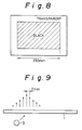
- Fig. 9 shows a state of intensity distribution of scattered light emergent from the scattering plate 1 after the light emitted from the light source 3 is scattered by the scattering plate 1. It is shown in Fig. 9 that the light is widely scattered by the scattering plate 1. The intensity of the scattered light little changes at a point 1/8 mm away from a point of the maximum intensity, or at a point 1/12 mm therefrom, but a change in quantity of light reaches 10 % or more at a point 2 mm away from the point of maximum intensity.
- the light emitted from the light source 3 passes through the glass table 2 and is then scattered by the scattering plate 1. Most of scattered light is reflected by the mirror 5 and passes through the lens 6 to reach the CCD sensor 7. A quantity of light reaching the CCD sensor 7 is converted into digital image data.
- the light emitted from the light source 3 passes through the glass table 2 and is then scattered by the scattering plate 1 similarly as in Fig. 2. Since a lot of scattered light is lost on this occasion, only a little scattered light is reflected by the mirror 5 and passes through the lens 6 to reach the CCD sensor 7. Accordingly, the quantity of light is greatly decreased at the reading end as compared with that at the reading start.
- the present invention has been accomplished solving the above problem. It is an object of the present invention to provide a scanner which can keep the quantity of light reaching the CCD sensor constant with a change in reading position.
- a scanner for reading an image on a document comprising: a light source for illuminating the document to provide optical information of the image; a reading optical unit for reading said optical information of the image; first moving means for moving the light source along the document; second moving means for moving the reading optical unit along the document; measuring means for measuring a moving amount of each of the light source and the reading optical unit as moved along a test chart to read a predetermined length on the test chart; storing means for storing information concerning said moving amounts; and correcting means for correcting a moving amount of the light source through said first moving means, based on the information thus stored, when said reading optical unit reads the optical information of the image on the document.
- the measuring means uses the reading optical unit in reading the test chart to measure a moving amount thereof.
- the reading optical unit may be a transmission-type reading optical unit which reads optical information of an image obtained when light from the light source passes through the document.
- the measuring means has a second reading optical unit which may be used to measure a moving amount of the light source.
- the second reading optical unit may be a reflection-type reading optical unit which reads information of an image obtained when light from the light source is reflected by the document.
- the storing means may be a programmable non-volatile memory.
- the test chart comprises a black portion of the predetermined length and a transparent portion transmitting light.
- the first and second moving means may be stepping motors.
- each of the stepping motors gives a moving amount of the light source or the first reading optical unit as a number of steps.
- the storing means may be an EEPROM, which stores a quotient and a remainder obtained by dividing the number of steps given by each stepping motor by a predetermined value.
- the test chart is first read to measure the moving amounts of the light source and the reading optical unit.
- the reading optical unit is first moved by a predetermined amount.
- the light source is moved with a correction based on the first measured moving amounts if necessary.
- a one-line reading process is carried out by the reading optical unit.
- the document is read by repeating movement of the optical unit, movement of the light source, and the one-line reading process.
- the scanner of the present invention is provided with the means for reading the test chart of the predetermined length to measure the respective moving amounts of the light source and the reading optical unit, the storing means for storing the measured moving amounts, and the means for correcting a moving amount of the light source, based on the thus measured moving amounts, the change in quantity of light depending upon a difference of reading position can be suppressed to the utmost.
- the scanner has the same structure as shown in Fig. 2.
- the scanner is provided with a scattering plate 1 on which a document (not shown) is placed, a glass table 2 for holding the scattering plate 1, a light source 3 located underneath the scattering plate 1, a TR optical unit 4 located over the scattering plate 1, a TR optical unit sensor 8 for determining a reference position of the TR optical unit 4, a RR optical unit 9 located underneath the scattering plate 1, and a RR optical unit sensor 13 for determining a reference position of the RR optical unit 9.
- the basic idea of the present invention is that a moving amount of the light source 3 is made coincident with a moving amount of the TR optical unit 4 to prevent a change in quantity of light.
- the present embodiment employs a method for adjusting the moving amount of light source 3 as to be equal to that of TR optical unit 4. The reason of this is that the position of TR optical unit 4 is an actual position of image reading.
- the moving amount of light source 3 is corrected as shown in Fig. 4 such that a moving amount b1' thereof becomes equal to a moving amount b2 of the optical unit 4.
- the scanner of the present embodiment permits two modes of reflection document reading and transmission document reading, and has a resolution of 8 lines/mm.
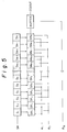
- Fig. 7 is a circuit block diagram of the scanner in the embodiment of the present invention.
- the scanner includes a CCD sensor 71 for receiving drive signals SH, ⁇ 1, ⁇ 2, ⁇ R from a scanner control circuit 74 and outputting CCDOUT as the CCD output, an AD converter 72 for receiving the CCD output of CCDOUT and converting it into a digital single, an EEPROM (electrically erasable programmable read-only memory) 73 for holding specified moving amounts of the light source 3 and the TR optical unit 4, a lighting unit 75 for lighting the light source 3, a stepping motor drive circuit 79 for driving a stepping motor 78, and a stepping motor drive circuit 77 for driving a stepping motor 76.
- EEPROM electrically erasable programmable read-only memory
- the AD converter 72 converts an output CCDOUT from the CCD sensor 71 into digital data at a leading edge of ⁇ R on the 256-level gray scale and then transmits the 8-bit data AD0 to AD7 to the control circuit 74.
- the EEPROM 73 has 8-bit I/O lines D0 to D7 connected to the control circuit 74, and its read-write signal R/W is supplied from the control circuit 74. Further, address signals A0, A1 are also supplied from the control circuit 74. Accordingly, the EEPROM 73 is one having a capacity of 4x8 bits. When an address receives certain data, the data is written in the address with R/W of '0' or the data is output from the address with R/W of '1'.
- the lighting unit 75 lights the light source when a signal LON from the control circuit is '1'.
- the stepping motor drive circuit 77 moves the light source 3 and the reflection optical unit 9 together forward or backward at the minimum step of 1/8 mm, as shown in Fig. 2.
- a control signal FORB from the control circuit 74 is '1' and if a drive signal STEPB from the control circuit is changed once from '0' to '1', the light source 3 and the reflection optical unit 9 move 1/8 mm forward.
- the control signal FORB is equal to '0' and if the drive signal STEPB is changed once from '0' to '1', they move 1/8 mm backward.
- the stepping motor drive circuit 79 moves the TR optical unit 4 forward or backward at the minimum step of 1/8 mm in Fig. 2.
- a control signal FORA and a drive signal STEPA from the control circuit 74 have the same functions as FORB and STEPB.
- Fig. 8 shows a test chart for measuring the moving amounts, which is used in the both modes of reflection and transmission.
- the test chart is a transparent film on which a black pattern is formed for example in the length of 250 mm.
- a white sheet larger than the test chart is set on the test chart.
- test chart of Fig. 8 is scanned in the transmission mode and in the white/black binary mode with resolution of 8 lines/mm.
- 2008 steps were necessary for scanning the entire length of black portion in the test chart.
- the black portion should be scanned by 2000 steps ideally, extra 8 steps were needed because of variations in the driving portion.
- test chart of Fig. 8 is scanned in the reflection mode and in the white/black binary mode with resolution of 8 lines/mm (actually with the white sheet being set on the test chart).
- the entire length of the black portion was scanned by 1995 steps in the reflection mode.
- a difference between the two moving amounts is 0.11882 mm, which will not greatly change the intensity of light from the light source in the final reading after movement of 250 mm as compared with that in the reading start.
- the number of pulses for the optical unit 4 is basically neither decreased nor increased for the correction. This can prevent an oblique line from being stepped when read.
- a difference between the two moving amounts is 1.62258 mm.
- the intensity of light from the light source in the final reading after movement of 250 mm would be largely different from that in the reading start.
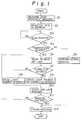
- Step S1 a basic moving amount is measured in each of the transmission mode and the reflection mode, using the test chart of Fig. 8.
- the test chart in Fig. 8 is scanned in the white/black binary mode with resolution of 8 lines/mm to measure a number of steps necessary for scanning the black portion in the test chart. Then, a number of steps in the transmission mode is integrally divided by 256.
- AH be an obtained quotient and AL be a remainder.
- the same operation is conducted in the reflection mode.
- a number of steps in the reflection mode is integrally divided by 256.
- BH be an obtained quotient and BL be a remainder.
- Step S2 the values of AL, AH, BL and BH obtained at Step S1 are stored in EEPROM 73, which is programmable and which can store the values even in a power-off condition.
- AL is stored at address 0, AH at address 1, BL at address 2, and BH at address 3.
- Step S3 it is judged at Step S3 whether an instruction of document scan start is provided through an instructing device (not shown). The judgment is repeated at Step S3 before an instruction is given. When an instruction is given, the flow proceeds to the next step.
- Step S4 It is next judged at Step S4 whether the transmission reading or the normal reading should be conducted. Whether the transmission reading or the normal reading should be conducted is instructed through the unrepresented instructing device.
- Step S6 The flow goes to Step S6 if the transmission reading is instructed. If not, the normal reading (reflection reading) is conducted at Step S5. Then the follow goes to Step S12.
- the TR optical unit 4 is driven by a certain feed amount corresponding to the resolution.
- Step S7 It is then judged at Step S7 whether the correction of moving amount of light source is necessary.
- a step correction amount XB of light source 3 can be calculated as follows for a moving step number XA of the optical unit 4.
- XB XA(BHx256+BL-AHx256-AL)/2000 If XB>0, an additional pulse or pulses are necessary; if XB ⁇ 0, a thin-out pulse or pulses are necessary.
- the moving amount of light source has to be corrected by the step number of XB for the total drive step number XA of the optical unit.
- the above correction is effected on the moving amount of the light source.
- Step S8 In case it is judged that no correction is needed for a moving amount of light source, the flow goes to Step S8 to drive the light source by an amount corresponding to the resolution by normal steps.
- Step S9 moves the light source by a corrected amount by steps obtained by adding a step to normal steps or thinning out a step from the normal steps.
- Step S10 One-line reading is next carried out at Step S10. It is judged at Step S11 whether the reading is completed. Unless the reading is completed, the flow returns to Step S6. A reading finishing process is conducted at Step S12.
- the relative positional relation is kept accurate between the TR optical unit and the light source, so that the quantity of light can be kept unchanged regardless of the reading position, suppressing a change in brightness or a change in color balance of read image.
- the effect can be easily attained without highly increasing the accuracy of driving system and without requiring a special mechanical component except for the electrical memory element (EEPROM).
Applications Claiming Priority (2)
| Application Number | Priority Date | Filing Date | Title |
|---|---|---|---|
| JP5101400A JP2889080B2 (ja) | 1993-04-27 | 1993-04-27 | スキャナ |
| JP101400/93 | 1993-04-27 |
Publications (3)
| Publication Number | Publication Date |
|---|---|
| EP0622944A2 true EP0622944A2 (fr) | 1994-11-02 |
| EP0622944A3 EP0622944A3 (fr) | 1995-11-15 |
| EP0622944B1 EP0622944B1 (fr) | 1998-12-23 |
Family
ID=14299689
Family Applications (1)
| Application Number | Title | Priority Date | Filing Date |
|---|---|---|---|
| EP94106526A Expired - Lifetime EP0622944B1 (fr) | 1993-04-27 | 1994-04-26 | Système de balayage |
Country Status (5)
| Country | Link |
|---|---|
| US (1) | US5455412A (fr) |
| EP (1) | EP0622944B1 (fr) |
| JP (1) | JP2889080B2 (fr) |
| CA (1) | CA2121611C (fr) |
| DE (1) | DE69415384T2 (fr) |
Cited By (1)
| Publication number | Priority date | Publication date | Assignee | Title |
|---|---|---|---|---|
| FR2749944A1 (fr) * | 1996-06-17 | 1997-12-19 | Canon Kk | Appareil de lecture d'images |
Families Citing this family (7)
| Publication number | Priority date | Publication date | Assignee | Title |
|---|---|---|---|---|
| JP3376030B2 (ja) * | 1993-07-08 | 2003-02-10 | キヤノン株式会社 | 画像読取装置 |
| JP3793600B2 (ja) * | 1996-02-20 | 2006-07-05 | 株式会社オプトエレクトロニクス | 光学的パターン読取装置 |
| US5693937A (en) * | 1996-04-29 | 1997-12-02 | Must Systems, Inc. | Image information reading apparatus with an internal document tray |
| US5959745A (en) * | 1996-04-29 | 1999-09-28 | Must Systems, Inc. | Transmission mechanism for an image information reading apparatus |
| US6338432B1 (en) * | 1997-02-19 | 2002-01-15 | Opticon Inc | Optical pattern reading apparatus with movable optical unit |
| TW555328U (en) * | 2002-10-25 | 2003-09-21 | Lite On Technology Corp | Image scanner |
| US10158834B2 (en) * | 2016-08-30 | 2018-12-18 | Hand Held Products, Inc. | Corrected projection perspective distortion |
Citations (3)
| Publication number | Priority date | Publication date | Assignee | Title |
|---|---|---|---|---|
| US4989099A (en) * | 1987-10-16 | 1991-01-29 | Kabushiki Kaisha Toshiba | Image information reading apparatus |
| US5130525A (en) * | 1990-09-28 | 1992-07-14 | Xerox Corporation | Method and apparatus for real time motion and image analysis |
| EP0516092A2 (fr) * | 1991-05-28 | 1992-12-02 | Shinko Electric Co. Ltd. | Dispositif de lecture d'image |
Family Cites Families (5)
| Publication number | Priority date | Publication date | Assignee | Title |
|---|---|---|---|---|
| US4893196A (en) * | 1987-04-09 | 1990-01-09 | Kabushiki Kaisha Toshiba | Image reading apparatus |
| JPH03158066A (ja) * | 1989-11-15 | 1991-07-08 | Fujitsu Ltd | 原稿読取位置調整方法 |
| JPH04156167A (ja) * | 1990-10-19 | 1992-05-28 | Fuji Photo Film Co Ltd | 画像読取装置および透過原稿ユニット |
| JPH0575804A (ja) * | 1991-09-17 | 1993-03-26 | Toshiba Corp | 画像形成装置 |
| US5282053A (en) * | 1991-10-23 | 1994-01-25 | Xerox Corporation | Scan image processing |
-
1993
- 1993-04-27 JP JP5101400A patent/JP2889080B2/ja not_active Expired - Fee Related
-
1994
- 1994-04-19 CA CA002121611A patent/CA2121611C/fr not_active Expired - Fee Related
- 1994-04-26 EP EP94106526A patent/EP0622944B1/fr not_active Expired - Lifetime
- 1994-04-26 US US08/233,691 patent/US5455412A/en not_active Expired - Lifetime
- 1994-04-26 DE DE69415384T patent/DE69415384T2/de not_active Expired - Fee Related
Patent Citations (3)
| Publication number | Priority date | Publication date | Assignee | Title |
|---|---|---|---|---|
| US4989099A (en) * | 1987-10-16 | 1991-01-29 | Kabushiki Kaisha Toshiba | Image information reading apparatus |
| US5130525A (en) * | 1990-09-28 | 1992-07-14 | Xerox Corporation | Method and apparatus for real time motion and image analysis |
| EP0516092A2 (fr) * | 1991-05-28 | 1992-12-02 | Shinko Electric Co. Ltd. | Dispositif de lecture d'image |
Cited By (4)
| Publication number | Priority date | Publication date | Assignee | Title |
|---|---|---|---|---|
| FR2749944A1 (fr) * | 1996-06-17 | 1997-12-19 | Canon Kk | Appareil de lecture d'images |
| EP0814421A2 (fr) * | 1996-06-17 | 1997-12-29 | Canon Kabushiki Kaisha | Dispositif de lecture d'image |
| EP0814421A3 (fr) * | 1996-06-17 | 1999-06-16 | Canon Kabushiki Kaisha | Dispositif de lecture d'image |
| US6229628B1 (en) | 1996-06-17 | 2001-05-08 | Canon Kabushiki Kaisha | Image reading apparatus |
Also Published As
| Publication number | Publication date |
|---|---|
| CA2121611C (fr) | 1999-07-13 |
| EP0622944A3 (fr) | 1995-11-15 |
| DE69415384D1 (de) | 1999-02-04 |
| DE69415384T2 (de) | 1999-06-17 |
| CA2121611A1 (fr) | 1994-10-28 |
| JPH06311316A (ja) | 1994-11-04 |
| EP0622944B1 (fr) | 1998-12-23 |
| US5455412A (en) | 1995-10-03 |
| JP2889080B2 (ja) | 1999-05-10 |
Similar Documents
| Publication | Publication Date | Title |
|---|---|---|
| EP0439357B1 (fr) | Procédé et appareil pour la provision de compensation du détecteur dans un balayeur de documents | |
| US7031029B2 (en) | Method for setting black reference data used for excess exposure, and image reading apparatus | |
| US20090097078A1 (en) | Image reading apparatus and image reading method | |
| EP0590559B1 (fr) | Dispositif de lecture d'images | |
| US5455412A (en) | Document scanner employing a test chart to correlate the independent motion of the light source and the reader | |
| US6633415B1 (en) | Image input apparatus and method for controlling the same | |
| EP0613291A1 (fr) | Appareil d'analyse d'images avec correction de l'effet d'ombre améliorée et mesure d'un rapport de quantité de lumière | |
| US5357351A (en) | Image reading device | |
| US7251064B2 (en) | Calibration of an image scanning system | |
| US20020054385A1 (en) | Image processing apparatus | |
| US4916549A (en) | Image sensing apparatus with shading compensation | |
| EP0401567B1 (fr) | Lecteur d'image | |
| EP0814421B1 (fr) | Dispositif de lecture d'image | |
| US4754153A (en) | Operating radiation sensors to avoid transfer loss | |
| JP3222803B2 (ja) | 画像読取装置 | |
| US6791726B2 (en) | Photosensor array with decreased scan time for decreased optical sampling rates | |
| JPH01300760A (ja) | 画像読取装置 | |
| KR100268340B1 (ko) | 셔틀방식 스캐너의 쉐이딩 보정방법 | |
| JPH10108014A (ja) | カラー画像読取り装置 | |
| JP2852807B2 (ja) | 画像読取装置 | |
| KR100277732B1 (ko) | 셔틀방식 스캐너의 쉐이딩 보정방법 | |
| JPH03241968A (ja) | 画像読取装置 | |
| JPH0289744A (ja) | 画像読取装置 | |
| JPH0399581A (ja) | 原稿読取装置 | |
| JPH0195669A (ja) | 原稿読取装置 |
Legal Events
| Date | Code | Title | Description |
|---|---|---|---|
| PUAI | Public reference made under article 153(3) epc to a published international application that has entered the european phase |
Free format text: ORIGINAL CODE: 0009012 |
|
| AK | Designated contracting states |
Kind code of ref document: A2 Designated state(s): DE FR GB |
|
| PUAL | Search report despatched |
Free format text: ORIGINAL CODE: 0009013 |
|
| AK | Designated contracting states |
Kind code of ref document: A3 Designated state(s): DE FR GB |
|
| 17P | Request for examination filed |
Effective date: 19960126 |
|
| GRAG | Despatch of communication of intention to grant |
Free format text: ORIGINAL CODE: EPIDOS AGRA |
|
| 17Q | First examination report despatched |
Effective date: 19971222 |
|
| GRAG | Despatch of communication of intention to grant |
Free format text: ORIGINAL CODE: EPIDOS AGRA |
|
| GRAH | Despatch of communication of intention to grant a patent |
Free format text: ORIGINAL CODE: EPIDOS IGRA |
|
| GRAH | Despatch of communication of intention to grant a patent |
Free format text: ORIGINAL CODE: EPIDOS IGRA |
|
| GRAA | (expected) grant |
Free format text: ORIGINAL CODE: 0009210 |
|
| RAP1 | Party data changed (applicant data changed or rights of an application transferred) |
Owner name: SHARP KABUSHIKI KAISHA |
|
| AK | Designated contracting states |
Kind code of ref document: B1 Designated state(s): DE FR GB |
|
| REF | Corresponds to: |
Ref document number: 69415384 Country of ref document: DE Date of ref document: 19990204 |
|
| ET | Fr: translation filed | ||
| PLBE | No opposition filed within time limit |
Free format text: ORIGINAL CODE: 0009261 |
|
| STAA | Information on the status of an ep patent application or granted ep patent |
Free format text: STATUS: NO OPPOSITION FILED WITHIN TIME LIMIT |
|
| 26N | No opposition filed | ||
| REG | Reference to a national code |
Ref country code: GB Ref legal event code: IF02 |
|
| PGFP | Annual fee paid to national office [announced via postgrant information from national office to epo] |
Ref country code: FR Payment date: 20090417 Year of fee payment: 16 Ref country code: DE Payment date: 20090428 Year of fee payment: 16 |
|
| PGFP | Annual fee paid to national office [announced via postgrant information from national office to epo] |
Ref country code: GB Payment date: 20090422 Year of fee payment: 16 |
|
| GBPC | Gb: european patent ceased through non-payment of renewal fee |
Effective date: 20100426 |
|
| REG | Reference to a national code |
Ref country code: FR Ref legal event code: ST Effective date: 20101230 |
|
| PG25 | Lapsed in a contracting state [announced via postgrant information from national office to epo] |
Ref country code: DE Free format text: LAPSE BECAUSE OF NON-PAYMENT OF DUE FEES Effective date: 20101103 |
|
| PG25 | Lapsed in a contracting state [announced via postgrant information from national office to epo] |
Ref country code: GB Free format text: LAPSE BECAUSE OF NON-PAYMENT OF DUE FEES Effective date: 20100426 |
|
| PG25 | Lapsed in a contracting state [announced via postgrant information from national office to epo] |
Ref country code: FR Free format text: LAPSE BECAUSE OF NON-PAYMENT OF DUE FEES Effective date: 20100430 |