EP0620171B1 - Anlage zum Sortieren von Plattenmaterial - Google Patents
Anlage zum Sortieren von Plattenmaterial Download PDFInfo
- Publication number
- EP0620171B1 EP0620171B1 EP93810263A EP93810263A EP0620171B1 EP 0620171 B1 EP0620171 B1 EP 0620171B1 EP 93810263 A EP93810263 A EP 93810263A EP 93810263 A EP93810263 A EP 93810263A EP 0620171 B1 EP0620171 B1 EP 0620171B1
- Authority
- EP
- European Patent Office
- Prior art keywords
- sorting
- compartment
- carriage
- glass
- glass panes
- Prior art date
- Legal status (The legal status is an assumption and is not a legal conclusion. Google has not performed a legal analysis and makes no representation as to the accuracy of the status listed.)
- Expired - Lifetime
Links
Images
Classifications
-
- B—PERFORMING OPERATIONS; TRANSPORTING
- B65—CONVEYING; PACKING; STORING; HANDLING THIN OR FILAMENTARY MATERIAL
- B65G—TRANSPORT OR STORAGE DEVICES, e.g. CONVEYORS FOR LOADING OR TIPPING, SHOP CONVEYOR SYSTEMS OR PNEUMATIC TUBE CONVEYORS
- B65G49/00—Conveying systems characterised by their application for specified purposes not otherwise provided for
- B65G49/05—Conveying systems characterised by their application for specified purposes not otherwise provided for for fragile or damageable materials or articles
- B65G49/06—Conveying systems characterised by their application for specified purposes not otherwise provided for for fragile or damageable materials or articles for fragile sheets, e.g. glass
- B65G49/067—Sheet handling, means, e.g. manipulators, devices for turning or tilting sheet glass
-
- B—PERFORMING OPERATIONS; TRANSPORTING
- B07—SEPARATING SOLIDS FROM SOLIDS; SORTING
- B07C—POSTAL SORTING; SORTING INDIVIDUAL ARTICLES, OR BULK MATERIAL FIT TO BE SORTED PIECE-MEAL, e.g. BY PICKING
- B07C5/00—Sorting according to a characteristic or feature of the articles or material being sorted, e.g. by control effected by devices which detect or measure such characteristic or feature; Sorting by manually actuated devices, e.g. switches
- B07C5/04—Sorting according to size
-
- B—PERFORMING OPERATIONS; TRANSPORTING
- B65—CONVEYING; PACKING; STORING; HANDLING THIN OR FILAMENTARY MATERIAL
- B65G—TRANSPORT OR STORAGE DEVICES, e.g. CONVEYORS FOR LOADING OR TIPPING, SHOP CONVEYOR SYSTEMS OR PNEUMATIC TUBE CONVEYORS
- B65G1/00—Storing articles, individually or in orderly arrangement, in warehouses or magazines
- B65G1/02—Storage devices
- B65G1/04—Storage devices mechanical
-
- B—PERFORMING OPERATIONS; TRANSPORTING
- B65—CONVEYING; PACKING; STORING; HANDLING THIN OR FILAMENTARY MATERIAL
- B65G—TRANSPORT OR STORAGE DEVICES, e.g. CONVEYORS FOR LOADING OR TIPPING, SHOP CONVEYOR SYSTEMS OR PNEUMATIC TUBE CONVEYORS
- B65G49/00—Conveying systems characterised by their application for specified purposes not otherwise provided for
- B65G49/05—Conveying systems characterised by their application for specified purposes not otherwise provided for for fragile or damageable materials or articles
- B65G49/06—Conveying systems characterised by their application for specified purposes not otherwise provided for for fragile or damageable materials or articles for fragile sheets, e.g. glass
- B65G49/062—Easels, stands or shelves, e.g. castor-shelves, supporting means on vehicles
-
- B—PERFORMING OPERATIONS; TRANSPORTING
- B65—CONVEYING; PACKING; STORING; HANDLING THIN OR FILAMENTARY MATERIAL
- B65G—TRANSPORT OR STORAGE DEVICES, e.g. CONVEYORS FOR LOADING OR TIPPING, SHOP CONVEYOR SYSTEMS OR PNEUMATIC TUBE CONVEYORS
- B65G49/00—Conveying systems characterised by their application for specified purposes not otherwise provided for
- B65G49/05—Conveying systems characterised by their application for specified purposes not otherwise provided for for fragile or damageable materials or articles
- B65G49/06—Conveying systems characterised by their application for specified purposes not otherwise provided for for fragile or damageable materials or articles for fragile sheets, e.g. glass
- B65G49/068—Stacking or destacking devices; Means for preventing damage to stacked sheets, e.g. spaces
Definitions
- the present invention relates to a system for sorting sheet material, in particular when preparing and feeding sorted glass sheets to a further processing system, according to the preamble of claim 1.
- a system is known, for example, from EP-B-0 048 334.
- Such systems are used, for example, the centrally controlled production, in particular of groups of certain glass panes.
- groups of glass panes correspond to a specific order for a specific glazing unit, and it is necessary to program and centrally control the entire system, including the processing system mentioned, in such a way that large numbers of glass panes are fed and processed in the correct order.
- the sorting system in particular, serves this purpose, the sorting trolley receiving the raw glass panes and transferring them into predetermined compartments of one or more compartment trolleys.
- a stationary conveyor system for introducing prepared glass panes into the sorting trolley, and a mobile conveyor device is connected to the sorting trolley for transferring glass panes from the sorting trolley into compartment trolleys.
- This version is complex and does not allow optimal, gentle conveying of the glass panes.
- the two conveying devices both of which lie outside the compartments of the sorting trolley receiving the glass panes, take up a relatively large amount of space.
- the aim of the present invention is to simplify the known system and to optimize the handling and handling of the plates, e.g. Glass panes to allow.
- This goal is achieved according to the characterizing part of claim 1.
- the conveyor device preferably has a displaceable pliers for grasping a plate edge. These tongs are arranged within the loading space of the sorting trolley, so that the conveyor device does not take up any additional space.
- this embodiment according to the invention also permits optimal, gentle handling of the plates, in particular glass panes.
- Claim 4 describes a preferred solution of particular importance.
- a set-up device according to FIG. 5 can be used at various points in the system in order to keep plates, in particular glass panes, in a contact-free, approximately vertical position.
- This contact-free mounting of the plates not only has the advantage that damage, e.g. the fine coating of glass panes can be avoided, but that the plates can also be easily gripped and transported by suitable conveying means, in particular the aforementioned pliers.
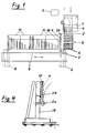
- the part of the system shown schematically in FIG. 1 is used for preparing and sorting the individual glass panes.
- cut glass panes are broken according to a specific plan, if necessary the individual panes are rotated in the manner indicated in FIG. 1 so that they leave the table 1 in the longitudinal direction via a belt transport 2, and waste is thrown into a container 3.
- a monitor is preferably mounted on the side of the table 1 opposite the operator, on which the cutting plan and the required information about the sequence of the glass panes to be removed are displayed.
- the belt conveyor 2 conveys the individual, prepared glass panes, for example the glass pane 4 indicated in FIG. 1, onto the pivoting support grate 5 of a set-up machine 6. This installation machine will be explained in more detail later with reference to FIGS. 2 and 3.
- the glass panes fed here in the horizontal position are brought into the vertical position by the erecting machine 6 and then drawn into a sorting carriage 8 by means of pliers 7.
- This sorting trolley 8 has two tongs 7 and correspondingly 2 compartments for receiving a glass pane 4 each, the sorting trolley 8 being brought into the position in which one of its tongs can grip and pull in a glass pane 4.
- the sorting trolley 8, as indicated in FIG. 1, can be displaced along a guide 9 in order to transfer individual glass panes into compartment trolleys 10.
- the system shown has four compartment trolleys 10 which can be set up along the guideway 9 in a precisely defined position.
- Each compartment trolley has, for example, 100 compartments for holding 100 glass panes, so that up to 400 glass panes can be sorted and distributed into the individual compartments of the compartment trolleys according to the specified program.
- FIG. 1 indicates that the compartments of the compartment trolleys 10 are only partially covered with glass panes.
- the compartment trolleys 10 are generally not fully filled with glass panes in the sorting station according to FIG. 1, but rather certain compartments of these trolleys generally remain unoccupied and are subsequently supplemented by manually or machine-supplied special glasses.
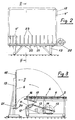
- FIGS. 2-4 show the erection machine 6, FIG. 2 being a view II in FIG. 3, FIG. 3 being a schematic section along line III-III in FIG. 2 and FIG. 4 being a detail from FIG. 3 on a larger scale.
- the pivotable grate 5 is connected to a lever 11 which is pivotable about a pivot axis 12 and on which the crank rod 13 of a crank mechanism 15 driven by a motor 14 can be pivoted.
- a pivotable stop 16 is attached to the grate 5, which is normally in the effective position shown, but can be pivoted and disengaged by means of a pneumatic cylinder 17.
- an air duct 21 to which air can be supplied by a blower 22, which can then emerge upwards through individual, wedge-like grooves 23 between the support wall 18 and a glass pane 4 standing in front of it.
- An air curtain is thus built up between the support wall 18 and the glass pane 4 standing in front of it, which largely holds the glass pane in a vertical position at a certain distance from the support wall 18, regardless of its size.
- FIG. 2 it is indicated that from the smallest glass panes 4 'to the largest 4''all can be held in an upright position.
- the support wall 18 with the blower 22 and the channel 21 is referred to below simply as an air cushion wall.
- the glass panes 4 run during their transfer from the table 1 to the grate 5 against end stops (not shown) Rust so that its front edge is in a certain position even in the erected position according to FIGS. 2 to 4.
- FIGS. 2 to 4 it is indicated that the front edges of the glass panes 4 'and 4''assume the same position regardless of their size. This is an essential prerequisite for the transfer of the glass panes from the installation machine into the sorting trolley 8.
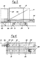
- This sorting trolley is shown in FIGS. 5 and 6.
- the sorting trolley is movable along the guide profiles 9 and can be positioned exactly in this direction by the motor 24 in order to take over glass panes from the installation machine or to insert glass panes into a compartment of a compartment trolley 10.
- This takeover or this insertion is carried out by a pair of pliers 25, the construction of which is indicated in FIG. 6, but is not described in detail.
- the actual grippers 26 of the pliers can be opened and closed by means of a pneumatic cylinder 27, the movement of the pliers being guided in parallel by the indicated parallelograms.
- the gripping surfaces of the pliers are covered with soft, well-adhering material so that the pliers exert the necessary force to pull out or push in even the largest glass panes.
- the pliers 25 grip the glass panes only at the extreme edge to a depth of, for example, 12 mm, where a certain damage to the pane coating can be accepted because the glass panes are reworked in this area anyway.
- the two pliers can be moved along guides 30 by means of drive motors 28 and chains 29, each over a row of rollers 31, on which the glass panes 4 roll with their lower edge when being pulled in or ejected.
- strips 33 and 34 are attached to frames 32 with nylon brushes.
- the glass panes are held in an upright position between these brushes and cannot be damaged, even if the sorting trolley for transferring glass panes into the compartment trolleys 10 is accelerated or decelerated relatively strongly.
- the infeed movement of the sorting trolley must take place with high precision, for which purpose preferably 9 racks are attached to the guides, in which pinions driven by the motor 24 engage.
- the sorting trolley 8 When the sorting trolley 8 with one of its compartments, or its tongs 7, which hold the glass pane along the guides 9 during the delivery of the sorting trolley 8, has arrived and positioned in front of the relevant compartment of a compartment trolley 10, the glass pane is removed by means of the pliers 7 the sorting trolley 8 ejected and inserted into the corresponding compartment of the compartment trolley.
- the individual compartments of the compartment trolley 10 can be designed similarly to the compartments of the sorting trolley 8.
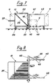
- FIGS. 7 and 8 show a compartment trolley 10 on a somewhat larger scale and with somewhat more details.
- Each carriage has fixed rollers 35 and swivel rollers 36, so that it can be moved by hand, for example with the aid of its handle 37.
- each compartment trolley 10 like the sorting trolley 8, has vertically standing frames 38, on which wires, ropes or rods coated with soft material, for example PVC, are attached for lateral support of the inserted glass panes 4.
- Vertical bars 40 between the compartments are also provided with a soft coating on the insertion side of the compartment trolley.
- the glass panes When the glass panes are manipulated, both during the transfer from the erecting machine into the sorting trolley and when transferring them from the sorting trolley into a compartment of a compartment trolley 10, the glass panes are permanently held by the pliers 7 which grasp them held and safely reach the correct end position without the risk of the glass panes touching fixed plant parts on the side and being damaged.
- FIGS. 7 and 8 schematically show a device 41 for supplementing the compartment trolley 10 with special glasses.
- This device has a guide 42 to which a compartment trolley 10 can be guided.
- An air cushion wall 43 of the type described above with a blower 44 is displaceable along the frame 42 and can be precisely positioned manually.
- Support rollers 45 are arranged below the air cushion wall 43, on which glass panes 4 are placed and can be held in the exact position in front of the air cushion wall 43 in the manner described.
- smaller special panes can be pushed into the specified compartment of the compartment trolley 10 by hand. Larger, heavier glass panes are prepared by means of the mobile air cushion wall as indicated in Figure 7.
- the air cushion wall is brought into the prescribed, precise position in front of the compartment trolley 10 and the prepared glass pane 4 is pushed manually into the corresponding compartment of the compartment trolley.
- the glass panes are always inserted into the compartment trolleys only by a distance corresponding to their length, or drawn into the sorting trolley 8.
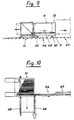
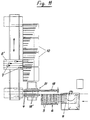
- compartment trolleys are fully occupied, they are brought into a precisely defined position in accordance with FIGS. 9 and 10 in front of a transfer device 46 for transferring the glass panes into a further processing system, for example an insulating glass line 47.
- the compartment trolley 10 is on guides 48 transversely to the stationary take-over device 46 can be moved and precisely positioned to remove glass panes from certain compartments in the pre-programmed order.
- the removal is carried out by a pair of pliers 7 indicated in FIG. 9, which can correspond to the pliers 7 of the sorting trolley, but which can be removed transversely from its movement path 49, in order then to allow the glass panes removed from the trolley 10 to pass into the further processing device 47.
- the device 46 also has an air cushion wall 18 in the sense of FIGS. 2-4, in front of which the glass panes are held in a defined position on support rollers (not shown).
- the air cushion wall 18 can be pivoted about the pivot bearing 50 indicated in FIG. 9 in order to tilt a glass pane 4 lying on it from the vertical position in which it was removed from the compartment trolley 10 into the position required for takeover by the processing device 47.
- This tilting movement can be a few degrees up to 90 °, ie the glass pane can be tilted from the vertical position into any intermediate position up to the horizontal position.
- FIG. 11 A purely schematic embodiment variant is shown in FIG. 11, in which corresponding system parts are identified in the same way as in the other figures.
- the installation machine 6 and the compartment trolley 10 are of identical design. The difference is that there is an intermediate storage or buffer 51 between the set-up machine 6 and the sorting trolley 8 ', which has 4 compartments and 4 tongs 7.
- This buffer 51 is also equipped with double-sided air cushion walls 18 ', on which up to 4 glass panes 4 can be positioned.
- the sorting trolley 8 ' can each take 4 glass panes from this buffer and transfer them one after the other into the assigned compartments of the compartment trolleys 10. With this buffer 51 or increasing the compartments and tongs in the sorting trolley, the sorting capacity can be increased.
Landscapes
- Engineering & Computer Science (AREA)
- Mechanical Engineering (AREA)
- Laminated Bodies (AREA)
- Branching, Merging, And Special Transfer Between Conveyors (AREA)
- Sorting Of Articles (AREA)
- Automobile Manufacture Line, Endless Track Vehicle, Trailer (AREA)
- Intermediate Stations On Conveyors (AREA)
- Specific Conveyance Elements (AREA)
- Re-Forming, After-Treatment, Cutting And Transporting Of Glass Products (AREA)
- Discharge Of Articles From Conveyors (AREA)
- Pretreatment Of Seeds And Plants (AREA)
- Paper (AREA)
Priority Applications (7)
| Application Number | Priority Date | Filing Date | Title |
|---|---|---|---|
| DK93810263.9T DK0620171T3 (da) | 1993-04-14 | 1993-04-14 | Anlæg til sortering af plademateriale |
| EP93810263A EP0620171B1 (de) | 1993-04-14 | 1993-04-14 | Anlage zum Sortieren von Plattenmaterial |
| AT93810263T ATE153977T1 (de) | 1993-04-14 | 1993-04-14 | Anlage zum sortieren von plattenmaterial |
| DE59306676T DE59306676D1 (de) | 1993-04-14 | 1993-04-14 | Anlage zum Sortieren von Plattenmaterial |
| ES93810263T ES2104109T3 (es) | 1993-04-14 | 1993-04-14 | Instalacion para la clasificacion de material en placas. |
| JP6075085A JPH072354A (ja) | 1993-04-14 | 1994-04-13 | 板材料の分類装置 |
| US08/226,981 US5511671A (en) | 1993-04-14 | 1994-04-13 | Installation for the sorting of plate material |
Applications Claiming Priority (1)
| Application Number | Priority Date | Filing Date | Title |
|---|---|---|---|
| EP93810263A EP0620171B1 (de) | 1993-04-14 | 1993-04-14 | Anlage zum Sortieren von Plattenmaterial |
Publications (2)
| Publication Number | Publication Date |
|---|---|
| EP0620171A1 EP0620171A1 (de) | 1994-10-19 |
| EP0620171B1 true EP0620171B1 (de) | 1997-06-04 |
Family
ID=8214949
Family Applications (1)
| Application Number | Title | Priority Date | Filing Date |
|---|---|---|---|
| EP93810263A Expired - Lifetime EP0620171B1 (de) | 1993-04-14 | 1993-04-14 | Anlage zum Sortieren von Plattenmaterial |
Country Status (7)
| Country | Link |
|---|---|
| US (1) | US5511671A (da) |
| EP (1) | EP0620171B1 (da) |
| JP (1) | JPH072354A (da) |
| AT (1) | ATE153977T1 (da) |
| DE (1) | DE59306676D1 (da) |
| DK (1) | DK0620171T3 (da) |
| ES (1) | ES2104109T3 (da) |
Cited By (3)
| Publication number | Priority date | Publication date | Assignee | Title |
|---|---|---|---|---|
| EP0738675A2 (fr) * | 1995-04-20 | 1996-10-23 | Antonio Piazza | Magasin à chariots mobiles portant des châssis inclinés |
| US6077018A (en) * | 1996-07-03 | 2000-06-20 | Lisec; Peter | Device for sorting of glass blanks |
| EP1323651A2 (de) | 2001-12-24 | 2003-07-02 | HEGLA Fahrzeug- u. Maschinenbau GmbH & Co. KG | Verfahren und Vorrichtung zum Sortieren von Glastafeln |
Families Citing this family (20)
| Publication number | Priority date | Publication date | Assignee | Title |
|---|---|---|---|---|
| DE4428897C2 (de) * | 1994-08-18 | 2000-04-27 | Lenhardt Maschinenbau | Vorrichtung zum Fördern und Zwischenspeichern von Isolierglasscheiben |
| DE19505771C1 (de) * | 1995-02-20 | 1996-09-26 | Lenhardt Maschinenbau | Anlage zum Herstellen von Isolierglasscheiben mit Abstandhalter auf Kunststoffbasis |
| IT1294798B1 (it) * | 1997-07-29 | 1999-04-15 | Giorgio Mistrello | Struttura di magazzino automatizzato per lastre di vetro o simili |
| KR19990037383A (ko) * | 1997-10-27 | 1999-05-25 | 세야 히로미치 | 평판형 재료를 공급하는 장치 |
| IT1319895B1 (it) * | 2000-02-08 | 2003-11-12 | Bottero Spa | Gruppo per la classificazione ed il trasferimento di lastre di vetro. |
| KR100633488B1 (ko) * | 2001-11-08 | 2006-10-13 | 샤프 가부시키가이샤 | 유리 기판의 분단 방법, 유리 기판의 분단 장치 및 액정 패널 제조 장치 |
| EP1431215A1 (de) * | 2002-12-19 | 2004-06-23 | Bystronic Maschinen AG | Verfahren und Vorrichtung zum beschicken einer Glasverarbeitungsanlage |
| CA2460859A1 (en) * | 2003-03-13 | 2004-09-13 | Bromer Inc. | Storage system for glass offcuts |
| CA2421121A1 (fr) * | 2003-03-13 | 2004-09-13 | Roger Mercure | Dispositif et methode pour la valorisation et l'optimisation de panneaux a decouper |
| ITPD20030081A1 (it) * | 2003-04-24 | 2004-10-25 | Alessandro Piazza | Macchinario per il carico e lo scarico di prodotti lastriformi |
| ITTO20030323A1 (it) * | 2003-04-29 | 2004-10-30 | Bottero Spa | Gruppo per l'immagazzinamento di spezzoni di lastre |
| DE502005000996D1 (de) * | 2004-04-23 | 2007-08-23 | Helga Fahrzeug Und Maschb Gmbh | Beladevorrichtung zum sortierenden Beladen einer Speichereinrichtung mit plattenförmigem Material |
| DE102005033644B4 (de) * | 2005-07-19 | 2007-04-12 | Bargstedt Handlingsysteme Gmbh | Verfahren zum Sortieren von plattenförmigen Werkstücken und Vorrichtung hierfür |
| IT1396296B1 (it) * | 2009-10-06 | 2012-11-16 | Bottero Spa | Impianto per l'alimentazione lastre di vetro. |
| US9896289B2 (en) | 2013-03-14 | 2018-02-20 | Southwall Technologies Inc. | Automated film pickup and placement method for insulating glass units |
| DE102018218141B4 (de) | 2018-05-04 | 2022-03-24 | Hegla Gmbh & Co. Kg | Sortierverfahren und -vorrichtung zum Sortieren von plattenförmigen Gegenständen, vorzugsweise Glastafelzuschnitten, Verfahren und Vorrichtung zum Herstellen von Glastafelzuschnitten mit einer derartigen Sortiervorrichtung |
| IT202000002275A1 (it) * | 2020-02-05 | 2020-05-05 | Forvet R&D S R L | Sistema per l'immagazzinamento e la gestione di lastre di vetro |
| CN112224609A (zh) * | 2020-08-29 | 2021-01-15 | 江苏晶品新能源科技有限公司 | 一种智能化单晶硅片分拣装置 |
| CN114798453B (zh) * | 2022-04-25 | 2023-08-15 | 武汉理工大学 | 全自动智能化仓储物流运输小车 |
| CN114655707B (zh) * | 2022-05-17 | 2022-08-05 | 南通东之杰智能装备有限公司 | 一种新能源汽车零部件智能搬运装置 |
Family Cites Families (2)
| Publication number | Priority date | Publication date | Assignee | Title |
|---|---|---|---|---|
| DE3162520D1 (en) * | 1980-09-24 | 1984-04-12 | Bystronic Masch | Apparatus for sorting unsorted glass plates of a glass-cutting installation |
| IT1202088B (it) * | 1985-06-07 | 1989-02-02 | Giben Impianti Spa | Impianto per l'impilamento di pacchi di pannelli di dimensione diversa, prodotti da un impianto di sezionatura e per ordinare le pile una vicino all'altra, onde formare degli agglomerati parallelepipediformi che vengono poi trasferiti in una stazione di scarico previa eventuale disposizione su di un pallet o su altro mezzo di appoggio e di protezione |
-
1993
- 1993-04-14 EP EP93810263A patent/EP0620171B1/de not_active Expired - Lifetime
- 1993-04-14 DE DE59306676T patent/DE59306676D1/de not_active Expired - Lifetime
- 1993-04-14 DK DK93810263.9T patent/DK0620171T3/da active
- 1993-04-14 ES ES93810263T patent/ES2104109T3/es not_active Expired - Lifetime
- 1993-04-14 AT AT93810263T patent/ATE153977T1/de not_active IP Right Cessation
-
1994
- 1994-04-13 US US08/226,981 patent/US5511671A/en not_active Expired - Lifetime
- 1994-04-13 JP JP6075085A patent/JPH072354A/ja active Pending
Cited By (3)
| Publication number | Priority date | Publication date | Assignee | Title |
|---|---|---|---|---|
| EP0738675A2 (fr) * | 1995-04-20 | 1996-10-23 | Antonio Piazza | Magasin à chariots mobiles portant des châssis inclinés |
| US6077018A (en) * | 1996-07-03 | 2000-06-20 | Lisec; Peter | Device for sorting of glass blanks |
| EP1323651A2 (de) | 2001-12-24 | 2003-07-02 | HEGLA Fahrzeug- u. Maschinenbau GmbH & Co. KG | Verfahren und Vorrichtung zum Sortieren von Glastafeln |
Also Published As
| Publication number | Publication date |
|---|---|
| ATE153977T1 (de) | 1997-06-15 |
| EP0620171A1 (de) | 1994-10-19 |
| ES2104109T3 (es) | 1997-10-01 |
| JPH072354A (ja) | 1995-01-06 |
| DE59306676D1 (de) | 1997-07-10 |
| DK0620171T3 (da) | 1997-07-28 |
| US5511671A (en) | 1996-04-30 |
Similar Documents
| Publication | Publication Date | Title |
|---|---|---|
| EP0620171B1 (de) | Anlage zum Sortieren von Plattenmaterial | |
| AT394987B (de) | Vorrichtung zum sortieren von glastafelzuschnitten | |
| DE19517804C2 (de) | Regalbediengerät | |
| WO1998005753A1 (de) | Objekt-lagervorrichtung, lagerstation und klimaschrank | |
| DE3502611C2 (da) | ||
| DE4117434A1 (de) | Verfahren und vorrichtung zum stapeln | |
| DE3829931A1 (de) | Bahnzufuehrvorrichtung | |
| DE19636470C2 (de) | Vorrichtung zum Handhaben von Glasscheiben | |
| EP1784651A1 (de) | Anlage zur behandlung mikrobiologischer proben | |
| DE2118523C3 (de) | Vorrichtung zum Bündeln von langgestrecktem Gut | |
| DE3109174A1 (de) | Ausschleusvorrichtung fuer eine foerderbahn | |
| DE3613462A1 (de) | Vorrichtung zum be- und entladen eines stapellifts | |
| DE3107437A1 (de) | Einrichtung zum beschicken eines werkzeugmaschinenauflagetisches | |
| DE102005002532A1 (de) | Vorrichtung und Verfahren zum automatisierten und zeitgleichen Bereitstellen und Wechseln von mindestens zwei Rollen aus Papierbahnen oder dergleichen für einen nachgeordneten Formatschneider | |
| DE3232180C2 (de) | Stapelvorrichtung für langgestrecktes Gut | |
| DE4205923A1 (de) | Vorrichtung zum abstapeln von schalen oder dergleichen, insbesondere geschirrschalen | |
| DE2051227A1 (de) | Warenpaternoster mit an Umlauf Kettenstrangen befestigten Gehangen | |
| EP0405064A1 (de) | Vorrichtung zum Vereinzeln und/oder Entnehmen von Profilstäben | |
| DE3235855C2 (de) | Vorrichtung zum automatischen Palettieren von gebündelten Stapeln aus Zeitungen und dergleichen | |
| CH618939A5 (da) | ||
| EP0734975A1 (de) | Regallager mit Ziehregalen | |
| EP0256403B1 (de) | Verfahren zum automatischen Überführen von Sektflaschendrahtbügeln von einer Bearbeitungsstation zu einer Ablage bzw. von einer Ablage zu einer Weiterbearbeitungsstation sowie Vorrichtung zur Durchführung des Verfahrens | |
| EP1210270B1 (de) | Tray zur aufnahme und zum transport von flaschen | |
| DE3119418C2 (de) | Übergabevorrichtung beim Transport von Gegenständen zum Aufbringen von Überzügen | |
| EP0206992B1 (de) | Lageranlage |
Legal Events
| Date | Code | Title | Description |
|---|---|---|---|
| PUAI | Public reference made under article 153(3) epc to a published international application that has entered the european phase |
Free format text: ORIGINAL CODE: 0009012 |
|
| AK | Designated contracting states |
Kind code of ref document: A1 Designated state(s): AT BE CH DE DK ES FR GB GR IE IT LI LU MC NL PT SE |
|
| RBV | Designated contracting states (corrected) |
Designated state(s): AT BE CH DE DK ES FR GB IT LI NL SE |
|
| 17P | Request for examination filed |
Effective date: 19950406 |
|
| 17Q | First examination report despatched |
Effective date: 19960228 |
|
| GRAG | Despatch of communication of intention to grant |
Free format text: ORIGINAL CODE: EPIDOS AGRA |
|
| GRAH | Despatch of communication of intention to grant a patent |
Free format text: ORIGINAL CODE: EPIDOS IGRA |
|
| GRAH | Despatch of communication of intention to grant a patent |
Free format text: ORIGINAL CODE: EPIDOS IGRA |
|
| GRAA | (expected) grant |
Free format text: ORIGINAL CODE: 0009210 |
|
| ITF | It: translation for a ep patent filed |
Owner name: BARZANO' E ZANARDO MILANO S.P.A. |
|
| AK | Designated contracting states |
Kind code of ref document: B1 Designated state(s): AT BE CH DE DK ES FR GB IT LI NL SE |
|
| REF | Corresponds to: |
Ref document number: 153977 Country of ref document: AT Date of ref document: 19970615 Kind code of ref document: T |
|
| REG | Reference to a national code |
Ref country code: CH Ref legal event code: NV Representative=s name: AMMANN PATENTANWAELTE AG BERN Ref country code: CH Ref legal event code: EP |
|
| REF | Corresponds to: |
Ref document number: 59306676 Country of ref document: DE Date of ref document: 19970710 |
|
| REG | Reference to a national code |
Ref country code: DK Ref legal event code: T3 |
|
| GBT | Gb: translation of ep patent filed (gb section 77(6)(a)/1977) |
Effective date: 19970902 |
|
| REG | Reference to a national code |
Ref country code: ES Ref legal event code: FG2A Ref document number: 2104109 Country of ref document: ES Kind code of ref document: T3 |
|
| ET | Fr: translation filed | ||
| PLBE | No opposition filed within time limit |
Free format text: ORIGINAL CODE: 0009261 |
|
| STAA | Information on the status of an ep patent application or granted ep patent |
Free format text: STATUS: NO OPPOSITION FILED WITHIN TIME LIMIT |
|
| 26N | No opposition filed | ||
| REG | Reference to a national code |
Ref country code: GB Ref legal event code: IF02 |
|
| PG25 | Lapsed in a contracting state [announced via postgrant information from national office to epo] |
Ref country code: IT Free format text: LAPSE BECAUSE OF NON-PAYMENT OF DUE FEES Effective date: 20050414 |
|
| PGRI | Patent reinstated in contracting state [announced from national office to epo] |
Ref country code: IT Effective date: 20080301 |
|
| PGFP | Annual fee paid to national office [announced via postgrant information from national office to epo] |
Ref country code: GB Payment date: 20100331 Year of fee payment: 18 |
|
| PGFP | Annual fee paid to national office [announced via postgrant information from national office to epo] |
Ref country code: FR Payment date: 20100506 Year of fee payment: 18 Ref country code: ES Payment date: 20100426 Year of fee payment: 18 Ref country code: DK Payment date: 20100413 Year of fee payment: 18 |
|
| PGFP | Annual fee paid to national office [announced via postgrant information from national office to epo] |
Ref country code: NL Payment date: 20100413 Year of fee payment: 18 Ref country code: IT Payment date: 20100426 Year of fee payment: 18 Ref country code: DE Payment date: 20100423 Year of fee payment: 18 Ref country code: AT Payment date: 20100415 Year of fee payment: 18 |
|
| PGFP | Annual fee paid to national office [announced via postgrant information from national office to epo] |
Ref country code: CH Payment date: 20100512 Year of fee payment: 18 Ref country code: BE Payment date: 20100419 Year of fee payment: 18 |
|
| PGFP | Annual fee paid to national office [announced via postgrant information from national office to epo] |
Ref country code: SE Payment date: 20100415 Year of fee payment: 18 |
|
| BERE | Be: lapsed |
Owner name: *BYSTRONIC MASCHINEN A.G. Effective date: 20110430 |
|
| REG | Reference to a national code |
Ref country code: DE Ref legal event code: R119 Ref document number: 59306676 Country of ref document: DE |
|
| REG | Reference to a national code |
Ref country code: DE Ref legal event code: R119 Ref document number: 59306676 Country of ref document: DE |
|
| REG | Reference to a national code |
Ref country code: NL Ref legal event code: V1 Effective date: 20111101 |
|
| REG | Reference to a national code |
Ref country code: SE Ref legal event code: EUG |
|
| REG | Reference to a national code |
Ref country code: CH Ref legal event code: PL |
|
| GBPC | Gb: european patent ceased through non-payment of renewal fee |
Effective date: 20110414 |
|
| REG | Reference to a national code |
Ref country code: AT Ref legal event code: MM01 Ref document number: 153977 Country of ref document: AT Kind code of ref document: T Effective date: 20110414 |
|
| REG | Reference to a national code |
Ref country code: FR Ref legal event code: ST Effective date: 20111230 |
|
| PG25 | Lapsed in a contracting state [announced via postgrant information from national office to epo] |
Ref country code: CH Free format text: LAPSE BECAUSE OF NON-PAYMENT OF DUE FEES Effective date: 20110430 Ref country code: NL Free format text: LAPSE BECAUSE OF NON-PAYMENT OF DUE FEES Effective date: 20111101 Ref country code: FR Free format text: LAPSE BECAUSE OF NON-PAYMENT OF DUE FEES Effective date: 20110502 Ref country code: LI Free format text: LAPSE BECAUSE OF NON-PAYMENT OF DUE FEES Effective date: 20110430 Ref country code: BE Free format text: LAPSE BECAUSE OF NON-PAYMENT OF DUE FEES Effective date: 20110430 |
|
| REG | Reference to a national code |
Ref country code: DK Ref legal event code: EBP |
|
| PG25 | Lapsed in a contracting state [announced via postgrant information from national office to epo] |
Ref country code: GB Free format text: LAPSE BECAUSE OF NON-PAYMENT OF DUE FEES Effective date: 20110414 Ref country code: IT Free format text: LAPSE BECAUSE OF NON-PAYMENT OF DUE FEES Effective date: 20110414 Ref country code: AT Free format text: LAPSE BECAUSE OF NON-PAYMENT OF DUE FEES Effective date: 20110414 |
|
| REG | Reference to a national code |
Ref country code: ES Ref legal event code: FD2A Effective date: 20120524 |
|
| PG25 | Lapsed in a contracting state [announced via postgrant information from national office to epo] |
Ref country code: DK Free format text: LAPSE BECAUSE OF NON-PAYMENT OF DUE FEES Effective date: 20110430 |
|
| PG25 | Lapsed in a contracting state [announced via postgrant information from national office to epo] |
Ref country code: ES Free format text: LAPSE BECAUSE OF NON-PAYMENT OF DUE FEES Effective date: 20110415 |
|
| PG25 | Lapsed in a contracting state [announced via postgrant information from national office to epo] |
Ref country code: SE Free format text: LAPSE BECAUSE OF NON-PAYMENT OF DUE FEES Effective date: 20110415 |
|
| PG25 | Lapsed in a contracting state [announced via postgrant information from national office to epo] |
Ref country code: DE Free format text: LAPSE BECAUSE OF NON-PAYMENT OF DUE FEES Effective date: 20111031 |