EP0620081A1 - Méthode de positionnement d'un élément d'une machine, de préférence un outil, qui a un point de référence, par support à un point de référence fixe, de préférence à une butée ou une surface de support - Google Patents
Méthode de positionnement d'un élément d'une machine, de préférence un outil, qui a un point de référence, par support à un point de référence fixe, de préférence à une butée ou une surface de support Download PDFInfo
- Publication number
- EP0620081A1 EP0620081A1 EP94103023A EP94103023A EP0620081A1 EP 0620081 A1 EP0620081 A1 EP 0620081A1 EP 94103023 A EP94103023 A EP 94103023A EP 94103023 A EP94103023 A EP 94103023A EP 0620081 A1 EP0620081 A1 EP 0620081A1
- Authority
- EP
- European Patent Office
- Prior art keywords
- machine element
- reference point
- position indicator
- spindle
- stop
- Prior art date
- Legal status (The legal status is an assumption and is not a legal conclusion. Google has not performed a legal analysis and makes no representation as to the accuracy of the status listed.)
- Granted
Links
Images


Classifications
-
- B—PERFORMING OPERATIONS; TRANSPORTING
- B23—MACHINE TOOLS; METAL-WORKING NOT OTHERWISE PROVIDED FOR
- B23Q—DETAILS, COMPONENTS, OR ACCESSORIES FOR MACHINE TOOLS, e.g. ARRANGEMENTS FOR COPYING OR CONTROLLING; MACHINE TOOLS IN GENERAL CHARACTERISED BY THE CONSTRUCTION OF PARTICULAR DETAILS OR COMPONENTS; COMBINATIONS OR ASSOCIATIONS OF METAL-WORKING MACHINES, NOT DIRECTED TO A PARTICULAR RESULT
- B23Q17/00—Arrangements for observing, indicating or measuring on machine tools
- B23Q17/22—Arrangements for observing, indicating or measuring on machine tools for indicating or measuring existing or desired position of tool or work
-
- B—PERFORMING OPERATIONS; TRANSPORTING
- B23—MACHINE TOOLS; METAL-WORKING NOT OTHERWISE PROVIDED FOR
- B23Q—DETAILS, COMPONENTS, OR ACCESSORIES FOR MACHINE TOOLS, e.g. ARRANGEMENTS FOR COPYING OR CONTROLLING; MACHINE TOOLS IN GENERAL CHARACTERISED BY THE CONSTRUCTION OF PARTICULAR DETAILS OR COMPONENTS; COMBINATIONS OR ASSOCIATIONS OF METAL-WORKING MACHINES, NOT DIRECTED TO A PARTICULAR RESULT
- B23Q15/00—Automatic control or regulation of feed movement, cutting velocity or position of tool or work
- B23Q15/20—Automatic control or regulation of feed movement, cutting velocity or position of tool or work before or after the tool acts upon the workpiece
- B23Q15/22—Control or regulation of position of tool or workpiece
- B23Q15/24—Control or regulation of position of tool or workpiece of linear position
-
- G—PHYSICS
- G05—CONTROLLING; REGULATING
- G05B—CONTROL OR REGULATING SYSTEMS IN GENERAL; FUNCTIONAL ELEMENTS OF SUCH SYSTEMS; MONITORING OR TESTING ARRANGEMENTS FOR SUCH SYSTEMS OR ELEMENTS
- G05B2219/00—Program-control systems
- G05B2219/30—Nc systems
- G05B2219/37—Measurements
- G05B2219/37092—Display position actual and or target
-
- G—PHYSICS
- G05—CONTROLLING; REGULATING
- G05B—CONTROL OR REGULATING SYSTEMS IN GENERAL; FUNCTIONAL ELEMENTS OF SUCH SYSTEMS; MONITORING OR TESTING ARRANGEMENTS FOR SUCH SYSTEMS OR ELEMENTS
- G05B2219/00—Program-control systems
- G05B2219/30—Nc systems
- G05B2219/45—Nc applications
- G05B2219/45229—Woodworking
-
- G—PHYSICS
- G05—CONTROLLING; REGULATING
- G05B—CONTROL OR REGULATING SYSTEMS IN GENERAL; FUNCTIONAL ELEMENTS OF SUCH SYSTEMS; MONITORING OR TESTING ARRANGEMENTS FOR SUCH SYSTEMS OR ELEMENTS
- G05B2219/00—Program-control systems
- G05B2219/30—Nc systems
- G05B2219/50—Machine tool, machine tool null till machine tool work handling
- G05B2219/50018—Zero point floating
-
- G—PHYSICS
- G05—CONTROLLING; REGULATING
- G05B—CONTROL OR REGULATING SYSTEMS IN GENERAL; FUNCTIONAL ELEMENTS OF SUCH SYSTEMS; MONITORING OR TESTING ARRANGEMENTS FOR SUCH SYSTEMS OR ELEMENTS
- G05B2219/00—Program-control systems
- G05B2219/30—Nc systems
- G05B2219/50—Machine tool, machine tool null till machine tool work handling
- G05B2219/50019—Zero, null offset
-
- G—PHYSICS
- G05—CONTROLLING; REGULATING
- G05B—CONTROL OR REGULATING SYSTEMS IN GENERAL; FUNCTIONAL ELEMENTS OF SUCH SYSTEMS; MONITORING OR TESTING ARRANGEMENTS FOR SUCH SYSTEMS OR ELEMENTS
- G05B2219/00—Program-control systems
- G05B2219/30—Nc systems
- G05B2219/50—Machine tool, machine tool null till machine tool work handling
- G05B2219/50295—Tool offset by manual input by switches
-
- Y—GENERAL TAGGING OF NEW TECHNOLOGICAL DEVELOPMENTS; GENERAL TAGGING OF CROSS-SECTIONAL TECHNOLOGIES SPANNING OVER SEVERAL SECTIONS OF THE IPC; TECHNICAL SUBJECTS COVERED BY FORMER USPC CROSS-REFERENCE ART COLLECTIONS [XRACs] AND DIGESTS
- Y10—TECHNICAL SUBJECTS COVERED BY FORMER USPC
- Y10T—TECHNICAL SUBJECTS COVERED BY FORMER US CLASSIFICATION
- Y10T409/00—Gear cutting, milling, or planing
- Y10T409/30—Milling
- Y10T409/30784—Milling including means to adustably position cutter
- Y10T409/307952—Linear adjustment
- Y10T409/308176—Linear adjustment with position indicator or limit means
-
- Y—GENERAL TAGGING OF NEW TECHNOLOGICAL DEVELOPMENTS; GENERAL TAGGING OF CROSS-SECTIONAL TECHNOLOGIES SPANNING OVER SEVERAL SECTIONS OF THE IPC; TECHNICAL SUBJECTS COVERED BY FORMER USPC CROSS-REFERENCE ART COLLECTIONS [XRACs] AND DIGESTS
- Y10—TECHNICAL SUBJECTS COVERED BY FORMER USPC
- Y10T—TECHNICAL SUBJECTS COVERED BY FORMER US CLASSIFICATION
- Y10T83/00—Cutting
- Y10T83/849—With signal, scale, or indicator
- Y10T83/853—Indicates tool position
-
- Y—GENERAL TAGGING OF NEW TECHNOLOGICAL DEVELOPMENTS; GENERAL TAGGING OF CROSS-SECTIONAL TECHNOLOGIES SPANNING OVER SEVERAL SECTIONS OF THE IPC; TECHNICAL SUBJECTS COVERED BY FORMER USPC CROSS-REFERENCE ART COLLECTIONS [XRACs] AND DIGESTS
- Y10—TECHNICAL SUBJECTS COVERED BY FORMER USPC
- Y10T—TECHNICAL SUBJECTS COVERED BY FORMER US CLASSIFICATION
- Y10T83/00—Cutting
- Y10T83/849—With signal, scale, or indicator
- Y10T83/868—Counter
Definitions
- the invention relates to a method for positioning a machine element having a reference point, preferably a machining tool, relative to a reference point, preferably to a stop or a stop surface, according to the preamble of claim 1.
- processing machines it is known to position the respective processing tool as a machine element relative to a stop or to a support surface in order to process a workpiece in the required manner.
- the processing tool is adjusted with respect to a stop so that the wood has a predetermined width after processing.
- the setting of the processing tools or their spindles is complex. When the processing tools are changed, the positioning devices must always be zeroed again be made in the working position.
- the invention has for its object to design the generic method so that the machine element can be quickly and accurately adjusted to the required position in a simple manner.
- the machine element can be precisely and easily adjusted to the respective position using the two position indicators. If the distance of the reference point of the machine element from its effective part is set on the second position display, then the value characterizing the predetermined distance of the effective part of the machine element from the reference point is displayed on the first position display. This adjustment can be made quickly and precisely using the position indicator.
- the reference point and the reference point can be understood to mean axes or surfaces.
- An effective part can be understood to mean, for example, an outer edge, a peripheral surface, a working diameter of a tool or the flight circle of knives of a machining tool.
- stops, tools, measuring devices and the like can be easily and precisely positioned.
- the work pieces are processed on their long sides with processing tools.
- the machining tools In order to achieve a desired machining dimension, the machining tools must be set up exactly.
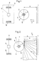
- the workpieces are guided past the processing tools and lie against a stop 1.
- the drawings show the case in which a workpiece 2 is conveyed past the machining tool 4 in the transport direction 3.
- the workpiece 2 lies on a (not shown) on and is guided along the stop 1 in the transport direction 3.
- the workpiece 2 is machined by the machining tool 4 on the side opposite the stop 1.
- it can be a profiling tool that sits on a spindle 5 in a rotationally fixed manner.
- the spindle 5 can be arranged vertically or horizontally or also obliquely in a processing machine, depending on how the corresponding workpiece 2 is to be processed. In the illustrated embodiment, the spindle 5 extends perpendicular to the transport direction 3 and in the vertical direction. If the spindle 5 lies horizontally above the workpiece to be machined, then the support surface for the workpiece is to be regarded as a stop.
- the processing tool 4 is brought into a basic position.
- a certain basic distance to the stop 1 is set with the aid of precisely measured measuring rings which are plugged onto the spindle 5.
- This distance value is then set on a position indicator 9 of a display device 8.
- Another position indicator 10 of the display device 8 is set to zero.
- This basic setting of the spindle 5 is carried out only once.
- the axis 6 of the spindle 5 has the basic distance from the stop 1.
- the spindle 5 is adjusted in the direction of the arrows 7 perpendicular to the stop 1 until the spindle axis 6 has the required distance from the stop 1 .
- the spindle 5 sits on a (not shown) displacement device, like a sled with which it can be easily adjusted relative to the stop 1.
- this adjusting device is connected to the display device 8, which has two position indicators 9 and 10. They can optionally be connected to the adjustment device of the spindle 5 via a switch 11, so that only one of the two position indicators 9 or 10 indicates a corresponding adjustment path of the spindle 5.
- the spindle 5 is set to the desired machining dimension h.
- the position indicator 9 shows this distance h of the spindle axis 6 from the stop 1, which is 80 mm in the exemplary embodiment. Since the flight circle 12 of the cutting knife (not shown) on the circumference of the processing tool 4 has a smaller distance from the stop 1, the processing tool 4 must now be removed so far from the stop 1 that the workpiece 2 can be machined to the dimension h with the cutting knives. This adjustment of the machining tool 4 can be carried out easily and simply.
- the switch 11 of the display device 8 is changed over so that when the spindle 5 is moved, only the position indicator 10, but not the position indicator 9, is adjusted.
- the machining tool 4 Since the spindle axis 6 has the distance h from the stop 1, the machining tool 4 now only has to be removed from the stop 1 by the radius r of the flight circle 12 of the cutting knives. Since the radius r of the flight circle of the machining tool 4 is known, the operator only has to adjust the spindle 5 to the extent that until the radius of the flight circle 12 is immediately displayed in the position display 10. In the exemplary embodiment shown, this flight circle radius r is 50 mm. As soon as the position indicator 10, which was set to zero in the basic setting according to FIG. 1, shows the value 50, the processing tool 4 has reached its exact position. The corresponding value can be read off easily on the position display 10, so that the operator can easily adjust the processing tool 4 into the exact position.
- the flight circle 12 of the machining tool 4 now has the desired distance h.
- the workpiece 2 to be machined can now be transported past the machining tool 4 in the transport direction 3. It is processed by the cutting blades of the processing tool 4 to the dimension h, that is to say 80 mm.
- the adjustment of the machining tool 4 required for this is very simple and nevertheless can be carried out precisely.
- the switch 11 of the display device 8 is switched over again so that the position indicator 10 is not adjusted when the processing tool 4 is adjusted, but only the position indicator 9. If, for example, the dimension h is no longer 80 mm, but only 60 mm, then that will be Starting from the position shown in FIG. 2, the processing tool 4 is adjusted in the direction of the stop 1 until the value 60 appears on the position display 9. Then the flight circle also has 12 of the machining tool 4 the distance of 60 mm from the stop 1. It is therefore possible to immediately move the workpiece 2 past the machining tool 4, whereby it is machined to the new dimension h of 60 mm.
- the position indicator 9 can be used to determine very precisely when the new dimension h has been reached.
- the other position indicator 10 is not adjusted when the spindle 5 is set, so that it continues to indicate the radius r of 50 mm of the flight circle 12 of the machining tool 4.
- the machining tool 4 can be adjusted simply and highly precisely into the respective position required for producing the machining dimension h.
- the machining dimension h is to be produced with a machining tool 4 with a different flight circle radius, the tool must again be adjusted accordingly. If this other tool 4 has a flight circle radius of only 30 mm, for example, then the tool must be moved closer to the stop 1 so that the workpiece 2 to be machined has the required machining dimension h of, for example, 80 mm.
- the switch 11 of the display device 8 is changed over so that the position indicator 10 is adjusted when the processing tool 4 has to be adjusted.
- the processing dimension h of 80 mm is therefore still shown in the position display 9. If the spindle 5 is now adjusted from the position shown in FIG. 2 with the new tool in the direction of the stop 1, then the value shown in the position indicator 10 changes by the amount of the adjustment path of the spindle 5.
- the spindle 5 Since the new flight radius r does not is more than 50, but only 30 mm, the spindle 5 must therefore be displaced in the direction of the stop 1 until the new circle radius value 30 is shown in the position display 10. This corresponds to an adjustment path of the spindle 5 by 20 mm. As soon as the new value 30 appears in the position display, the spindle 5 has reached its exact position. The workpiece 2 can now be guided past the processing tool 4, whereby it is also processed with the smaller tool to the dimension h of 80 mm.
- the spindle 5 is removed from the stop 1 until the value 30 appears in the position indicator 10. Then the flight circle of the machining tool again has the required distance h of 80 mm from the stop 1.
- the adjustment can also be carried out simply with machining tools which are larger in the flight circle diameter. If the machining dimension h is still to be, for example, 80 mm, the distance between the machining tool 4 and the stop 1 must be increased in this case. If the new machining tool is placed on the spindle 5, the position indicator 10 is first switched on with the switch 11. Now the machining tool 4 is shifted until the flight circle radius of the new machining tool appears in the position display 10. If it is 70 mm, for example, then the spindle 5 is removed from the stop 1 until the value 70 is shown in the position display 10. Then the flight circle diameter 12 has the required distance h of 80 mm from the stop in the exemplary embodiment 1. The workpiece 2 can then be guided past the machining tool 4, whereby it is also brought to dimension h with the larger tool.
- the position indicator 10 is switched on again with the switch 11. Because of the larger flight circle diameter, the spindle 5 must be brought at a greater distance from the stop 1.
- the originally set value 50 is initially shown in the position display 10. Since the new flight circle diameter is 70 mm, the spindle 5 must therefore be moved 20 mm further from the stop 1. This adjustment can be carried out easily.
- the spindle 5 is adjusted until the new value 70 is shown in the position display 10. Then the flight circle has the required distance h of 80 mm from the stop 1. The processing dimension h of 80 mm is still shown in the position display 9.
- the user can easily determine from the two position indicators 9 and 10 of the display device 8 which machining dimension h is set and which flight circle radius the machining tool 4 just used has.
- the spindle 5 must be adjusted closer to the stop 1 by the difference of 20 mm. Regardless of whether it is assumed from the setting shown in FIG. 1 or the position shown in FIG. 2, in both cases, the first Switch 11 of the display device 8, the position indicator 9 is set. Then the spindle 5 is adjusted in the direction of the arrow 7 in the direction of the stop 1 until the new value 60 appears in the position display 9. Then the new machining dimension h is set exactly.
- the spindle 5 is in the setting according to FIG. 1, the spindle must then be removed again from the stop 1 by the radius of the circle of the tool.
- the switch 11 is changed over in the manner described, so that the position indicator 10 is switched on.
- the spindle 5 is then moved until the flight circle radius of the machining tool seated on the spindle 5 is shown in the position display 10.
- the machining dimension h is first set in the manner described with the aid of the position indicator 9. Then, with the aid of the position indicator 10, the respective flight circle radius of the tool is adjusted by adjusting the spindle 5 in the required direction.
- the flight circle radius can also be set first and then the machining dimension.
- the two position indicators 9 and 10 of the display device 8 are independent of one another, are at 3 to 5, the position indicators 9 'and 10' of the display device 8 'are linked to one another.
- the position indicator 9 ' is coupled to the (not shown) displacement device of the spindle 5, so that the position indicator 9' is adjusted accordingly when the spindle 5 is displaced.
- the position indicator 10 ' stops when the spindle 5 is moved.
- the axis 6 of the spindle 5 again has the distance h from the stop 1.
- This distance h is the machining dimension for the workpiece 2.
- this dimension h is again 80 mm.
- This value is shown in the position display 9 '.
- the other position indicator 10 ' is decoupled from the position indicator 9' by means of the switch 11 ', so that it does not change its displayed value when the spindle 4 is adjusted.
- the turning circle radius r of the machining tool 4 is set with a rotary knob 13 in the position display 10 ′.
- the switch 11 ' is set again so that the two position indicators 9' and 10 'are coupled to one another.
- the turning circle radius r of the machining tool 4 which in the exemplary embodiment is 50 mm, is set on the position display 10 ′ using the rotary knob 13.
- the two position indicators 9 'and 10' are coupled to one another in such a way that the value displayed in the position indicator 9 'by that in the Position display 10 'set value is reduced. Therefore, if the value 50 is set in the position display 10 ', the position display 9' shows the value 30.
- the spindle 5 is not adjusted so that its axis 6 is still at a distance h from the stop 1.
- the position indicator 10 ' is decoupled from the position indicator 9' and the spindle 5 is adjusted relative to the stop 1 until the set value for the machining dimension h appears again in the position indicator 9 '.
- the position indicator 9' is adjusted in accordance with the adjustment of the spindle 5.
- the position 80 9 shows the value 80 which corresponds to the machining dimension h.
- the workpiece 2 can be transported past, whereby it is machined by the tool 4 to the dimension h.
- the machining dimension h can be changed quickly and easily.
- the measured dimension h is again set in the position display 9 '.
- This new dimension h is again determined between the spindle axis 6 and the stop 1.
- the rotary knob 13 on the position display 10 'the flight circle radius r is used Tool 4 set. Since the switch 11 'is set in this adjustment process so that the two position indicators 9' and 10 'are coupled to each other, when the circle radius r is set, the display value in the position indicator 9' is reduced by the appropriate amount. Finally, after switching the switch 11 'in the manner described, the tool 4 is adjusted with respect to the stop 1 until the machining dimension h appears again in the position display 9'. Since position indicator 10 'is uncoupled, the value it displays remains unchanged.
- the display device 8 ' can be used to achieve an exact adaptation of the machine without difficulty. It is only necessary to use the rotary knob 13 in the position of the tool spindle 5 according to FIG. 4 in the position display 10 'to enter the corresponding new value of the flight radius r. As described above, the value shown in the position display 9 'is changed accordingly. It is then only necessary to adjust the spindle 5 with the new tool so that the machining dimension h appears again in the position display 9 '.
- FIG. 6 also shows the possibility of the values to be displayed in the position display 10 ′′ of the display device 8 ′′ by means of a decade switch 14. With this decade switch 14, as has been described with reference to FIGS. 3 to 5, the respective flight circle radius r of the machining tool 4 is entered.
- FIG. 6 shows schematically that the mutual coupling of the adjusting device or tool carrier of the spindle 5 for the machining tool 4 with the display device or the displays can be achieved not only by a switch, but also by the structural design of the display device 8 '' and its linkage with the adjusting device or the tool carrier of the spindle 5 can result automatically.
- the adjustment or setting process takes place in the same way as has been described with reference to FIGS. 3 to 5. There is only no need to adjust the switch of the display device, which is not present in the embodiment according to FIG. 6.
- the positioning device of the spindle 5 should always be in the same direction, regardless of whether using the display 9, 9 ', 9' 'or the display 10, 10', 10 '' is positioned.
- the vertical spindles and the lower horizontal spindles are positioned in a known manner towards the wood, while the upper horizontal spindles are positioned upwards away from the wood.
- the displays can be mechanical or electrical displays.
Applications Claiming Priority (2)
| Application Number | Priority Date | Filing Date | Title |
|---|---|---|---|
| DE4311861A DE4311861A1 (de) | 1993-04-10 | 1993-04-10 | Verfahren zur Positionierung eines einen Bezugspunkt aufweisenden Maschinenelementes, vorzugsweise eines Bearbeitungswerkzeuges, relativ zu einem Referenzpunkt, vorzugsweise zu einem Anschlag oder einer Auflagefläche |
| DE4311861 | 1993-04-10 |
Publications (2)
| Publication Number | Publication Date |
|---|---|
| EP0620081A1 true EP0620081A1 (fr) | 1994-10-19 |
| EP0620081B1 EP0620081B1 (fr) | 1997-10-01 |
Family
ID=6485248
Family Applications (1)
| Application Number | Title | Priority Date | Filing Date |
|---|---|---|---|
| EP94103023A Expired - Lifetime EP0620081B1 (fr) | 1993-04-10 | 1994-03-01 | Méthode de positionnement d'un élément d'une machine, de préférence un outil, qui a un point de référence, par support à un point de référence fixe, de préférence à une butée ou une surface de support |
Country Status (4)
| Country | Link |
|---|---|
| US (1) | US5435360A (fr) |
| EP (1) | EP0620081B1 (fr) |
| JP (1) | JPH06324738A (fr) |
| DE (2) | DE4311861A1 (fr) |
Cited By (1)
| Publication number | Priority date | Publication date | Assignee | Title |
|---|---|---|---|---|
| EP1279465A1 (fr) * | 2001-07-27 | 2003-01-29 | Michael Weinig Aktiengesellschaft | Moulurière et procédé de positionnement au mois une broche de la moulurière |
Families Citing this family (5)
| Publication number | Priority date | Publication date | Assignee | Title |
|---|---|---|---|---|
| DE19803820A1 (de) * | 1998-01-31 | 1999-08-05 | Jagenberg Diana Gmbh | Maschine oder Zusatzaggregat zur Herstellung von gefalteten Behältern, insbesondere von Faltschachteln, aus Zuschnitten |
| DE19917537C5 (de) * | 1999-04-19 | 2010-04-22 | Otto Martin Maschinenbau Gmbh & Co. Kg | Holzbearbeitungsmaschine mit einer Korrekturvorrichtung |
| DE102004022217B8 (de) * | 2004-05-04 | 2015-12-31 | Masterwork Machinery Co., Ltd. | Faltschachtelklebemaschine zur Herstellung von Faltschachteln aus Zuschnitten |
| DE102004038385B4 (de) * | 2004-08-06 | 2010-07-01 | BöSha GmbH + Co. KG | Positionsrückmelder-Box für die Prozesstechnik |
| CN101901013B (zh) * | 2010-06-30 | 2012-11-14 | 深圳市润天智数字设备股份有限公司 | 一种距离调节机构 |
Citations (3)
| Publication number | Priority date | Publication date | Assignee | Title |
|---|---|---|---|---|
| DE2060044A1 (de) * | 1970-12-07 | 1972-06-22 | Bautz Gmbh Eduard | Verfahren zum Pruefen von Werkstuecken auf Arbeitsmaschinen und Vorrichtung zum Durchfuehren dieses Verfahrens |
| GB2059825A (en) * | 1979-10-10 | 1981-04-29 | Traub Gmbh | Determining tool tip position |
| DE3903906A1 (de) * | 1989-02-10 | 1989-06-15 | Martin Otto Maschbau Gmbh | Vorrichtung an tischfraesmaschinen fuer holz- oder kunststoffbearbeitung |
Family Cites Families (7)
| Publication number | Priority date | Publication date | Assignee | Title |
|---|---|---|---|---|
| US2134743A (en) * | 1936-07-03 | 1938-11-01 | Ingersoll Milling Machine Co | Position indicating mechanism for machine tools |
| FR61871E (fr) * | 1947-04-11 | 1955-05-18 | Machinesoutils Et D Outil Soc | Poste de sélection pour la commande d'organes de machines ou d'appareils |
| US3109635A (en) * | 1960-11-16 | 1963-11-05 | Goodman Mfg Co | Adjustable boring head for continuous mining machine |
| US3406601A (en) * | 1967-09-19 | 1968-10-22 | Clifford Francis Patrick | Automatic measuring apparatus |
| US3684939A (en) * | 1971-02-04 | 1972-08-15 | Allied Ind Components | Automatic positioning accessory for numerical control machine tools |
| DE3934137A1 (de) * | 1989-10-12 | 1991-04-25 | Boschert Ludwig Masch | Tischanschlag fuer eine stanzmaschine |
| FI84709C (fi) * | 1990-02-27 | 1992-01-10 | Paloheimo Oy | Anordning i traebearbetningsmaskiner. |
-
1993
- 1993-04-10 DE DE4311861A patent/DE4311861A1/de not_active Ceased
-
1994
- 1994-03-01 EP EP94103023A patent/EP0620081B1/fr not_active Expired - Lifetime
- 1994-03-01 DE DE59404186T patent/DE59404186D1/de not_active Expired - Lifetime
- 1994-04-08 US US08/224,858 patent/US5435360A/en not_active Expired - Lifetime
- 1994-04-08 JP JP6070838A patent/JPH06324738A/ja active Pending
Patent Citations (3)
| Publication number | Priority date | Publication date | Assignee | Title |
|---|---|---|---|---|
| DE2060044A1 (de) * | 1970-12-07 | 1972-06-22 | Bautz Gmbh Eduard | Verfahren zum Pruefen von Werkstuecken auf Arbeitsmaschinen und Vorrichtung zum Durchfuehren dieses Verfahrens |
| GB2059825A (en) * | 1979-10-10 | 1981-04-29 | Traub Gmbh | Determining tool tip position |
| DE3903906A1 (de) * | 1989-02-10 | 1989-06-15 | Martin Otto Maschbau Gmbh | Vorrichtung an tischfraesmaschinen fuer holz- oder kunststoffbearbeitung |
Non-Patent Citations (2)
| Title |
|---|
| ELGO ELECTRIC BROCHURE, FEBRUARY 1993 'Elgo Series 88P2 Position Controller' |
| ELGO ELECTRIC BROCHURE, MARCH 1988 'Elgo Series 71P Position Controller' |
Cited By (1)
| Publication number | Priority date | Publication date | Assignee | Title |
|---|---|---|---|---|
| EP1279465A1 (fr) * | 2001-07-27 | 2003-01-29 | Michael Weinig Aktiengesellschaft | Moulurière et procédé de positionnement au mois une broche de la moulurière |
Also Published As
| Publication number | Publication date |
|---|---|
| EP0620081B1 (fr) | 1997-10-01 |
| JPH06324738A (ja) | 1994-11-25 |
| DE4311861A1 (de) | 1994-10-13 |
| DE59404186D1 (de) | 1997-11-06 |
| US5435360A (en) | 1995-07-25 |
Similar Documents
| Publication | Publication Date | Title |
|---|---|---|
| DE2847510C2 (fr) | ||
| EP0254741B1 (fr) | Dispositif de retenue et de manipulation d'un objet plat | |
| EP0093288A1 (fr) | Dispositif d'ajustage automatique de la position radiale d'une glissière d'une tête de surfaçage pour une machine à enlèvement de copeaux | |
| EP0134910A1 (fr) | Procédé de découpage par électroérosion d'une chute d'une pièce ayant des surfaces parallèles | |
| DE19516073B4 (de) | Vorrichtung zum Stanzen von Nutzen aus Bögen | |
| EP0620081B1 (fr) | Méthode de positionnement d'un élément d'une machine, de préférence un outil, qui a un point de référence, par support à un point de référence fixe, de préférence à une butée ou une surface de support | |
| DE3112417A1 (de) | Vorrichtung zum einstellen der schneide eines in einem werkzeughalter eingesetzten werkzeuges ausserhalb einer werkzeugmaschine oder zum messen der schneidenlage | |
| DE2628728A1 (de) | Schneidvorrichtung mit rotierenden fluegelmessern zur herstellung von formschnitten in die raender bewegter werkstoffbahnen | |
| DE2127525C3 (de) | Zusatzeinrichtung für Drehautomaten zum spanlosen Ablängen von in der umlaufenden Werkstückspindel eingespannten Rohren oder dgl | |
| DE2319790A1 (de) | Maschine zum lochen von werkstuecken | |
| EP1279465B1 (fr) | Moulurière et procédé de positionnement d'au moins une broche de la moulurière | |
| DE2838735C2 (de) | Profilstahlschere | |
| DE3724455A1 (de) | Abkantgeraet | |
| DE863437C (de) | Vorrichtung zum serienweisen Bohren und Ausreiben von Werkstuecken | |
| DE3128198A1 (de) | Verfahren und vorrichtung zum herstellen von nut-feder-verbindungen in werkstuecken | |
| EP0126198B1 (fr) | Fraiseuse | |
| DE4229521B4 (de) | Verfahren zum Unwuchtausgleich eines Rotors | |
| DE102018217906A1 (de) | Vorrichtung zum Schneiden von Blech | |
| DE4401044B4 (de) | Hobelmaschine | |
| DE1502789A1 (de) | Einrichtung zur genauen Einstellung eines Werkstueckes bezueglich eines vorbestimmten Bezugspunktes | |
| EP0489708B1 (fr) | Dispositif de meulage | |
| DE3317026C1 (de) | Kopierfräsvorrichtung zum Fräsen von Beschlagsaussparungen in Tür- und Fensterprofile | |
| DE2853315C2 (de) | Einrichtung zum selbsttätigen Längspositionieren eines Werkstückes relativ zum Schleifwerkzeug an Rundschleifmaschinen | |
| AT397057B (de) | Aufteilmaschine für z.b. aus holz oder auch aus einem anderen material bestehende paneele | |
| DE19546362C2 (de) | Werkzeugschleifmaschine |
Legal Events
| Date | Code | Title | Description |
|---|---|---|---|
| PUAI | Public reference made under article 153(3) epc to a published international application that has entered the european phase |
Free format text: ORIGINAL CODE: 0009012 |
|
| AK | Designated contracting states |
Kind code of ref document: A1 Designated state(s): BE DE FR GB IT |
|
| 17P | Request for examination filed |
Effective date: 19941122 |
|
| 17Q | First examination report despatched |
Effective date: 19950317 |
|
| GRAG | Despatch of communication of intention to grant |
Free format text: ORIGINAL CODE: EPIDOS AGRA |
|
| GRAH | Despatch of communication of intention to grant a patent |
Free format text: ORIGINAL CODE: EPIDOS IGRA |
|
| GRAH | Despatch of communication of intention to grant a patent |
Free format text: ORIGINAL CODE: EPIDOS IGRA |
|
| GRAA | (expected) grant |
Free format text: ORIGINAL CODE: 0009210 |
|
| ITF | It: translation for a ep patent filed |
Owner name: BARZANO' E ZANARDO ROMA S.P.A. |
|
| AK | Designated contracting states |
Kind code of ref document: B1 Designated state(s): BE DE FR GB IT |
|
| GBT | Gb: translation of ep patent filed (gb section 77(6)(a)/1977) |
Effective date: 19971007 |
|
| REF | Corresponds to: |
Ref document number: 59404186 Country of ref document: DE Date of ref document: 19971106 |
|
| ET | Fr: translation filed | ||
| PG25 | Lapsed in a contracting state [announced via postgrant information from national office to epo] |
Ref country code: BE Free format text: LAPSE BECAUSE OF NON-PAYMENT OF DUE FEES Effective date: 19980331 |
|
| PLBQ | Unpublished change to opponent data |
Free format text: ORIGINAL CODE: EPIDOS OPPO |
|
| PLBI | Opposition filed |
Free format text: ORIGINAL CODE: 0009260 |
|
| PLBF | Reply of patent proprietor to notice(s) of opposition |
Free format text: ORIGINAL CODE: EPIDOS OBSO |
|
| 26 | Opposition filed |
Opponent name: WADKIN LIMITED Effective date: 19980630 |
|
| BERE | Be: lapsed |
Owner name: MICHAEL WEINIG A.G. Effective date: 19980331 |
|
| PLBF | Reply of patent proprietor to notice(s) of opposition |
Free format text: ORIGINAL CODE: EPIDOS OBSO |
|
| PLBF | Reply of patent proprietor to notice(s) of opposition |
Free format text: ORIGINAL CODE: EPIDOS OBSO |
|
| PLBF | Reply of patent proprietor to notice(s) of opposition |
Free format text: ORIGINAL CODE: EPIDOS OBSO |
|
| PLBO | Opposition rejected |
Free format text: ORIGINAL CODE: EPIDOS REJO |
|
| PLBN | Opposition rejected |
Free format text: ORIGINAL CODE: 0009273 |
|
| STAA | Information on the status of an ep patent application or granted ep patent |
Free format text: STATUS: OPPOSITION REJECTED |
|
| 27O | Opposition rejected |
Effective date: 20010403 |
|
| REG | Reference to a national code |
Ref country code: GB Ref legal event code: IF02 |
|
| PGFP | Annual fee paid to national office [announced via postgrant information from national office to epo] |
Ref country code: FR Payment date: 20040217 Year of fee payment: 11 |
|
| PG25 | Lapsed in a contracting state [announced via postgrant information from national office to epo] |
Ref country code: FR Free format text: LAPSE BECAUSE OF NON-PAYMENT OF DUE FEES Effective date: 20051130 |
|
| REG | Reference to a national code |
Ref country code: FR Ref legal event code: ST Effective date: 20051130 |
|
| PGFP | Annual fee paid to national office [announced via postgrant information from national office to epo] |
Ref country code: GB Payment date: 20110223 Year of fee payment: 18 |
|
| PG25 | Lapsed in a contracting state [announced via postgrant information from national office to epo] |
Ref country code: DE Free format text: LAPSE BECAUSE OF NON-PAYMENT OF DUE FEES Effective date: 20111001 |
|
| PGFP | Annual fee paid to national office [announced via postgrant information from national office to epo] |
Ref country code: IT Payment date: 20120307 Year of fee payment: 19 |
|
| PGFP | Annual fee paid to national office [announced via postgrant information from national office to epo] |
Ref country code: DE Payment date: 20120525 Year of fee payment: 19 |
|
| GBPC | Gb: european patent ceased through non-payment of renewal fee |
Effective date: 20120301 |
|
| PG25 | Lapsed in a contracting state [announced via postgrant information from national office to epo] |
Ref country code: GB Free format text: LAPSE BECAUSE OF NON-PAYMENT OF DUE FEES Effective date: 20120301 |
|
| REG | Reference to a national code |
Ref country code: DE Ref legal event code: R119 Ref document number: 59404186 Country of ref document: DE Effective date: 20131001 |
|
| PG25 | Lapsed in a contracting state [announced via postgrant information from national office to epo] |
Ref country code: IT Free format text: LAPSE BECAUSE OF NON-PAYMENT OF DUE FEES Effective date: 20130301 |
|
| PG25 | Lapsed in a contracting state [announced via postgrant information from national office to epo] |
Ref country code: DE Free format text: LAPSE BECAUSE OF NON-PAYMENT OF DUE FEES Effective date: 20131001 |