EP1279465A1 - Moulurière et procédé de positionnement au mois une broche de la moulurière - Google Patents
Moulurière et procédé de positionnement au mois une broche de la moulurière Download PDFInfo
- Publication number
- EP1279465A1 EP1279465A1 EP02016172A EP02016172A EP1279465A1 EP 1279465 A1 EP1279465 A1 EP 1279465A1 EP 02016172 A EP02016172 A EP 02016172A EP 02016172 A EP02016172 A EP 02016172A EP 1279465 A1 EP1279465 A1 EP 1279465A1
- Authority
- EP
- European Patent Office
- Prior art keywords
- spindle
- display
- spindles
- molding machine
- data memory
- Prior art date
- Legal status (The legal status is an assumption and is not a legal conclusion. Google has not performed a legal analysis and makes no representation as to the accuracy of the status listed.)
- Granted
Links
Images


Classifications
-
- B—PERFORMING OPERATIONS; TRANSPORTING
- B23—MACHINE TOOLS; METAL-WORKING NOT OTHERWISE PROVIDED FOR
- B23Q—DETAILS, COMPONENTS, OR ACCESSORIES FOR MACHINE TOOLS, e.g. ARRANGEMENTS FOR COPYING OR CONTROLLING; MACHINE TOOLS IN GENERAL CHARACTERISED BY THE CONSTRUCTION OF PARTICULAR DETAILS OR COMPONENTS; COMBINATIONS OR ASSOCIATIONS OF METAL-WORKING MACHINES, NOT DIRECTED TO A PARTICULAR RESULT
- B23Q17/00—Arrangements for observing, indicating or measuring on machine tools
- B23Q17/22—Arrangements for observing, indicating or measuring on machine tools for indicating or measuring existing or desired position of tool or work
-
- B—PERFORMING OPERATIONS; TRANSPORTING
- B23—MACHINE TOOLS; METAL-WORKING NOT OTHERWISE PROVIDED FOR
- B23Q—DETAILS, COMPONENTS, OR ACCESSORIES FOR MACHINE TOOLS, e.g. ARRANGEMENTS FOR COPYING OR CONTROLLING; MACHINE TOOLS IN GENERAL CHARACTERISED BY THE CONSTRUCTION OF PARTICULAR DETAILS OR COMPONENTS; COMBINATIONS OR ASSOCIATIONS OF METAL-WORKING MACHINES, NOT DIRECTED TO A PARTICULAR RESULT
- B23Q1/00—Members which are comprised in the general build-up of a form of machine, particularly relatively large fixed members
- B23Q1/0009—Energy-transferring means or control lines for movable machine parts; Control panels or boxes; Control parts
-
- B—PERFORMING OPERATIONS; TRANSPORTING
- B27—WORKING OR PRESERVING WOOD OR SIMILAR MATERIAL; NAILING OR STAPLING MACHINES IN GENERAL
- B27C—PLANING, DRILLING, MILLING, TURNING OR UNIVERSAL MACHINES FOR WOOD OR SIMILAR MATERIAL
- B27C5/00—Machines designed for producing special profiles or shaped work, e.g. by rotary cutters; Equipment therefor
- B27C5/02—Machines with table
-
- B—PERFORMING OPERATIONS; TRANSPORTING
- B27—WORKING OR PRESERVING WOOD OR SIMILAR MATERIAL; NAILING OR STAPLING MACHINES IN GENERAL
- B27F—DOVETAILED WORK; TENONS; SLOTTING MACHINES FOR WOOD OR SIMILAR MATERIAL; NAILING OR STAPLING MACHINES
- B27F1/00—Dovetailed work; Tenons; Making tongues or grooves; Groove- and- tongue jointed work; Finger- joints
- B27F1/02—Making tongues or grooves, of indefinite length
- B27F1/06—Making tongues or grooves, of indefinite length simultaneously along opposite edges of a board
-
- B—PERFORMING OPERATIONS; TRANSPORTING
- B27—WORKING OR PRESERVING WOOD OR SIMILAR MATERIAL; NAILING OR STAPLING MACHINES IN GENERAL
- B27M—WORKING OF WOOD NOT PROVIDED FOR IN SUBCLASSES B27B - B27L; MANUFACTURE OF SPECIFIC WOODEN ARTICLES
- B27M1/00—Working of wood not provided for in subclasses B27B - B27L, e.g. by stretching
- B27M1/08—Working of wood not provided for in subclasses B27B - B27L, e.g. by stretching by multi-step processes
-
- Y—GENERAL TAGGING OF NEW TECHNOLOGICAL DEVELOPMENTS; GENERAL TAGGING OF CROSS-SECTIONAL TECHNOLOGIES SPANNING OVER SEVERAL SECTIONS OF THE IPC; TECHNICAL SUBJECTS COVERED BY FORMER USPC CROSS-REFERENCE ART COLLECTIONS [XRACs] AND DIGESTS
- Y10—TECHNICAL SUBJECTS COVERED BY FORMER USPC
- Y10T—TECHNICAL SUBJECTS COVERED BY FORMER US CLASSIFICATION
- Y10T29/00—Metal working
- Y10T29/51—Plural diverse manufacturing apparatus including means for metal shaping or assembling
- Y10T29/5104—Type of machine
- Y10T29/5115—Planer
-
- Y—GENERAL TAGGING OF NEW TECHNOLOGICAL DEVELOPMENTS; GENERAL TAGGING OF CROSS-SECTIONAL TECHNOLOGIES SPANNING OVER SEVERAL SECTIONS OF THE IPC; TECHNICAL SUBJECTS COVERED BY FORMER USPC CROSS-REFERENCE ART COLLECTIONS [XRACs] AND DIGESTS
- Y10—TECHNICAL SUBJECTS COVERED BY FORMER USPC
- Y10T—TECHNICAL SUBJECTS COVERED BY FORMER US CLASSIFICATION
- Y10T29/00—Metal working
- Y10T29/51—Plural diverse manufacturing apparatus including means for metal shaping or assembling
- Y10T29/5122—Plural diverse manufacturing apparatus including means for metal shaping or assembling with means to feed work during tool contact
-
- Y—GENERAL TAGGING OF NEW TECHNOLOGICAL DEVELOPMENTS; GENERAL TAGGING OF CROSS-SECTIONAL TECHNOLOGIES SPANNING OVER SEVERAL SECTIONS OF THE IPC; TECHNICAL SUBJECTS COVERED BY FORMER USPC CROSS-REFERENCE ART COLLECTIONS [XRACs] AND DIGESTS
- Y10—TECHNICAL SUBJECTS COVERED BY FORMER USPC
- Y10T—TECHNICAL SUBJECTS COVERED BY FORMER US CLASSIFICATION
- Y10T29/00—Metal working
- Y10T29/51—Plural diverse manufacturing apparatus including means for metal shaping or assembling
- Y10T29/5136—Separate tool stations for selective or successive operation on work
-
- Y—GENERAL TAGGING OF NEW TECHNOLOGICAL DEVELOPMENTS; GENERAL TAGGING OF CROSS-SECTIONAL TECHNOLOGIES SPANNING OVER SEVERAL SECTIONS OF THE IPC; TECHNICAL SUBJECTS COVERED BY FORMER USPC CROSS-REFERENCE ART COLLECTIONS [XRACs] AND DIGESTS
- Y10—TECHNICAL SUBJECTS COVERED BY FORMER USPC
- Y10T—TECHNICAL SUBJECTS COVERED BY FORMER US CLASSIFICATION
- Y10T409/00—Gear cutting, milling, or planing
- Y10T409/30—Milling
- Y10T409/306664—Milling including means to infeed rotary cutter toward work
- Y10T409/307224—Milling including means to infeed rotary cutter toward work with infeed control means energized in response to activator stimulated by condition sensor
- Y10T409/30728—In response to cutter condition
Definitions
- the invention relates to a moulder according to the preamble of claim 1 and a method for adjusting at least one of the spindles of such a moulder according to the preamble of claim 10.
- the workpieces are machined on several sides with tools sitting on the spindles.
- the spindles must be adjusted to the dimensions of the workpiece and the profile to be produced on this workpiece. It is known to store the profile data and the measured tool data in a memory. From this stored profile and tool data, the setting values for the spindles for generating the desired profile are calculated by a program.
- the invention has for its object to design the generic moulder and the generic method so that the adjustment device provided for adjusting the spindle is simple and inexpensive.
- the spindle is set in a predetermined position relative to the machine-side reference point.
- the associated position value is displayed on the display device.
- the position value of the spindle is stored in the data memory as the actual value. If the spindle is to be set to this position again, the stored actual value is retrieved from the data memory and displayed again on the display device.
- the operator of the moulder according to the invention then only has to adjust the spindle according to the method of the invention so that the actual value indicated on the display device matches the retrieved setpoint and also shown on the display device. A program from which the setting data must be determined is not required.
- the moulder according to the invention can therefore be manufactured inexpensively.
- the display device can also be designed in such a way that when the setpoint is called up from the data memory, the difference to the current actual position of the spindle is displayed. In this case, the operator of the moulder according to the invention must adjust the spindle so that the displayed differential value is brought to zero.
- the moulder is used for processing workpieces made of wood, plastic and the like, which are transported for processing on their sides by the moulder in a known manner.
- the moulder has a transport path 1 on which the workpieces (not shown) are transported. During their transport through the molding machine, these workpieces rest against a stop 2, which extends over the length of the molding machine and is interrupted in the area by lateral spindles.
- the workpieces are transported in Fig. 1 from right to left on the conveyor track 1.
- transport rollers 3 are provided which rest on the workpiece and are rotatably driven.
- the transport rollers 3 are suspended from a transport bar 4, which is located at a distance above the transport path 1.
- the workpieces are first machined with a tool 5, which is seated on a horizontal dressing spindle located in the area below the transport path 1. With this tool 5, the underside of the workpiece is machined, in particular planed.
- the transport path 1 has a corresponding opening for the passage of the tool 5.
- the moulder In the transport direction at a distance behind the lower dressing spindle, the moulder is provided with a vertical spindle 6, on which a tool 7 is seated, with which the right side of the workpieces is machined in the transport direction.
- the spindle 6 sits on a cross slide 8, which preferably extends perpendicular to the direction of transport of the workpieces through the moulder. With the cross slide 8, the tool 7 can be moved transversely, preferably perpendicularly to the transport direction.
- a tool 9 which is located on the left side of the workpieces to be machined in the transport direction.
- This tool 9 is fixed on a vertical spindle.
- the tool 9 together with the spindle is mounted on a cross slide 10 which can be moved transversely, preferably perpendicularly to the direction of transport of the workpieces.
- the two cross slides 8, 10 are spaced apart.
- the upper sides of the cross slide 8, 10 advantageously lie in one plane with the upper side of the transport path 1, so that the workpieces can be conveyed without problems during the transition from the transport path 1 to the cross slide 8, 10.
- the upper sides of the cross slide 8, 10 can also be lower. Then separate table tops form the transport path 1 in this area.
- a tool 11 is located at a distance behind the tool 9 and is seated in a rotationally fixed manner on a horizontal spindle which is arranged in the region above the transport path 1 and the workpieces.
- the top of the workpiece is machined with the tool 11, for example planed straight.
- the moulder can have other subsequent tools, such as additional lower spindles.
- a wide variety of machining operations on the workpieces can be carried out in a simple manner on the moulder.
- the Tools 5, 7, 9, 11 set according to FIG. 1 then the workpieces which are transported along the stop ruler 2 extending in the transport direction are first planed with the tool 5 on their underside.
- the long side of the workpiece lying on the right in the transport direction is then planed with the tool 7.
- the left longitudinal side of the workpiece lying in the transport direction is planed straight with the tool 9 on the left in the transport direction, and the finished workpiece width is thus determined.
- the subsequent tool 11 the upper side of the workpiece is finally planed and thus the thickness of the finished workpiece is determined.
- the tools 5, 7, 9, 11 can also be profile tools, i.e. they carry profile knives which have the desired profile.
- the corresponding sides of the workpiece are thus profiled.
- planing tools on one spindle and profile tools on other spindles so that the corresponding sides of the workpiece are planed or profiled.
- the workpieces After passing through the moulder, the workpieces were machined on their sides.
- the workpieces are passed one behind the other at various tools 5, 7, 9, 11, which carry out the corresponding processing on the workpieces.
- the moulder is provided with an adjusting device which has display devices 12 for the different axis adjustments (FIG. 2). All of the display devices 12 are connected to a data memory 13, in which the actual dimensions of all the spindles 12 under a certain program number, as will be described later or a program or profile name. If the moulder is to be set again for the corresponding workpiece profile, the setting data which are stored under the corresponding program number or the corresponding program or profile name in the memory 13 are called up and transmitted to the individual display devices 12.
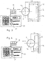
- Fig. 3 shows the workpiece 14 to be machined, which is transported along the stop ruler 2 in the transport direction 15 through the moulder.
- the workpiece 14 is to be machined on its left side in the transport direction 15 with the tool 9, which is fixed on the spindle 16 in a rotationally fixed manner.
- the spindle 16 is set here with respect to the stop ruler 2 so that it is 150 mm from the stop ruler 2.
- the workpiece 14 has the width dimension 17 before the processing by the tool 9. After the processing by the tool 9, the workpiece 14 has only the smaller width dimension 18.
- the display device 12 assigned to the spindle 16 sits on the corresponding adjusting spindle for the tool spindle 16 and has a display 19 in which the distance of the spindle 16 from the stop ruler 2 is preferably displayed electronically.
- the value 150 appears in the display 19.
- the display device 12 is connected in a known manner to the adjusting spindle via a sleeve (not shown) and determines the distance of the distance via the rotary movement of the adjusting spindle, taking into account the spindle pitch, for example according to the principle of an encoder Machine spindle 9 from the stop ruler 2, which is shown in the display 19.
- the settings are stored under a program number, a program or profile name in a defined order in the data memory 13.
- the data are stored under the name "Profile 1".
- the memory key 21 is pressed on an input device 20 which is provided with an alphanumeric keyboard 24.
- Fig. 4 shows the case that a new workpiece 14 with a profile 2 with a smaller width 17 is to be machined with the tool 9 on the spindle 16 than in the embodiment of FIG. 3.
- the spindle 16 is adjusted so that it has, for example, the distance of 75 mm from the stop ruler 2 of the moulder.
- This set dimension appears on the display 19 of the display device 12. All the spindles of the moulder are set on the new workpiece 14 with the profile 2 with the width dimension 17, the corresponding positions of the respective spindles of the moulder appearing on the display 19 of the respective display device 12.
- the settings of the various spindles are transmitted to the data memory 13 in the defined order by pressing the memory key 21 of the input device 20 and, in the exemplary embodiment, stored under the name "Profile 2".
- the position data of pressure elements are advantageously also recorded and stored in the data memory 13.
- the pressure elements are in a known manner before and after that on the Corresponding spindle seated tool arranged and rest on the workpiece 14.
- the pressure elements are adjusted relative to the tool in order to exert an optimal pressure effect on the workpiece 14.
- the pressure elements are also advantageously associated with display devices 12, with which the position of the pressure elements is detected in the same way as for the spindles.
- One of these display devices 12 ' can be seen in FIG. 1, with which the position of the one pressure element (not shown) associated with the upper horizontal spindle is detected.
- This display device 12 ' is also connected to the data memory 13.
- 5 and 6 show the case in which the setting data for the spindles of the moulder are to be called up from the data memory 13 in order to produce the profile 1 on the workpiece 14. It is shown as an example that the value 75 is shown in the lower field of the display 19 of the corresponding display device, from which it follows that the spindle 16 for the tool 9 is arranged at a distance of 75 mm from the stop ruler 2 of the moulder.
- the name “profile 1” is first set in a display 23 of the input device 20 on the input device 20 and then the call key 22 is pressed.
- the setting data stored under the designation “profile 1” in the data memory 13 are transmitted in the defined sequence to the respective display devices 12 and are displayed in the upper field of the display 19.
- the spindle 16 is arranged at a distance of 150 mm from the stop ruler 2 during the production of the profile 1. Accordingly, this value is shown in the upper display field of the display 19 of the associated display device 12.
- the instantaneous value for the distance of the spindle 16 from the stop ruler 2 is given, which in the exemplary embodiment is 75 mm.
- the operator of the moulder must now adjust the spindle 16 so far until the value 150 appears in the lower display field of the display 19 (FIG. 6). Then the spindle 16 has a distance of 150 mm from the stop ruler 2.
- the setting data stored under the name “Profile 1” are also transmitted to the respective display devices 12 in this way to the respective spindles.
- the operator of the moulder then only has to ensure that the same values are indicated in the two display fields of the respective display devices.
- the corresponding data from the data memory 13 are also transmitted to the display devices 12 ′ assigned to the pressure elements. If the setpoint deviates from the actual value, the corresponding pressure element is adjusted so that the displayed actual value matches the setpoint.
- a test run of a workpiece is carried out to check whether the settings of the moulder are correct. If, for example, the flight circle diameter of the tool 9 has changed in the time between saving the setting data and calling it up again, for example by regrinding the cutting knives, the required adjustment of the respective spindle can be determined and carried out after the test run.
- the new actual data are then, as has been explained with reference to FIGS. 3 and 4, transferred to the memory 13 by pressing the memory key 21 of the input device 20 and the corresponding designation.
- the molding machine can be set in the manner described using the setting device with very little effort and easily to the workpiece profile to be produced.
- the setting data stored in the data memory 13 are actual data during the acquisition, which are based on the retrieval from the memory are shown as target data in the display 19 of the respective display device 12.
- the operator of the moulder only has to set the respective spindle in such a way that the actual position of the spindle corresponds to the target position called up by the data memory 13. This can be monitored very easily in the display with the two display fields. If the profile produced on the workpiece 14 after it has been tested by the moulder does not match the target profile, for example because the tools have been reground, the setting of the spindles is corrected accordingly.
- the new setting dimensions are then in turn transmitted to the data memory as actual dimensions in the manner described.
- the moulder can be adjusted with the mechanical display devices in the usual way according to determined setting and tool data or also according to a wood sample.
- the display device 12, 12 ' has the display 19 with the two display fields in which the actual value and the target value are displayed.
- the display device 12, 12 ' can also be designed such that when the setpoint values are called up from the data memory 13, only the difference value from the current actual position is shown in the display 19. The operator of the moulder must then make the adjustment so that the difference value is brought to zero.
- adjustable elements such as stops, rulers, table tops and the like, which have to be adjusted manually in relation to the tools or workpieces.
- a linear measuring system such as a linear potentiometer or magnetic tape, which are coupled to a corresponding display device which displays the actual and target value or the differential value in the manner described. Setting these elements is also easy.
- the display device 12, 12 ' only shows the actual value or the target value in its display 19.
- a switch (not shown) can be used to switch between the two displayed values. Even then, the various spindles and adjustable elements can be easily and reliably adjusted to the required position.
- the display 19 of the display device 12, 12 ' shows the actual and the desired value for setting the elements to a new position. If both values match, only the actual value that corresponds to the setpoint is shown in the display 19. If the corresponding element is adjusted from the set position, for example to make a subsequent correction or because the element has been inadvertently adjusted, the operator is visually advised of this adjustment. The operator then knows that the actual and target values do not match. This can be done, for example, by a flashing representation of the value shown on the display 19, by a change in the color of the value, by a symbol or the like which also appears on the display. In such a case, the operator switches over the display device so that the actual value and the target value are shown again in the display 19. The operator can then adjust the element so that the actual and target values match again. This adjustment is particularly necessary if the element has been inadvertently adjusted.
- the new actual position is stored in the memory 13 as a new setpoint in the manner described.
Landscapes
- Engineering & Computer Science (AREA)
- Life Sciences & Earth Sciences (AREA)
- Mechanical Engineering (AREA)
- Wood Science & Technology (AREA)
- Forests & Forestry (AREA)
- Machine Tool Sensing Apparatuses (AREA)
- Injection Moulding Of Plastics Or The Like (AREA)
- Making Paper Articles (AREA)
Applications Claiming Priority (2)
| Application Number | Priority Date | Filing Date | Title |
|---|---|---|---|
| DE10136767 | 2001-07-27 | ||
| DE10136767A DE10136767A1 (de) | 2001-07-27 | 2001-07-27 | Kehlmaschine sowie Verfahren zur Einstellung wenigstens einer der Spindeln der Kehlmaschine |
Publications (2)
| Publication Number | Publication Date |
|---|---|
| EP1279465A1 true EP1279465A1 (fr) | 2003-01-29 |
| EP1279465B1 EP1279465B1 (fr) | 2007-09-12 |
Family
ID=7693382
Family Applications (1)
| Application Number | Title | Priority Date | Filing Date |
|---|---|---|---|
| EP02016172A Expired - Fee Related EP1279465B1 (fr) | 2001-07-27 | 2002-07-20 | Moulurière et procédé de positionnement d'au moins une broche de la moulurière |
Country Status (4)
| Country | Link |
|---|---|
| US (1) | US6695021B2 (fr) |
| EP (1) | EP1279465B1 (fr) |
| DE (2) | DE10136767A1 (fr) |
| TW (1) | TW564211B (fr) |
Cited By (2)
| Publication number | Priority date | Publication date | Assignee | Title |
|---|---|---|---|---|
| EP2153936A1 (fr) | 2008-08-14 | 2010-02-17 | Homag Holzbearbeitungssysteme AG | Machine pouvant être rééquipée, en particulier machine de traitement et procédé correspondant |
| EP2992993A1 (fr) * | 2014-09-04 | 2016-03-09 | Homag Holzbearbeitungssysteme GmbH | Dispositif et procede destines au positionnement d'un element de serrage |
Families Citing this family (2)
| Publication number | Priority date | Publication date | Assignee | Title |
|---|---|---|---|---|
| WO2007076195A2 (fr) | 2005-11-22 | 2007-07-05 | Genus, Inc. | Appareil de depot de couche atomique (ald) a tranche unique et a ecoulement symetrique de petit volume |
| DE102009021729A1 (de) * | 2009-05-11 | 2010-11-18 | Michael Weinig Ag | Maschine zum Bearbeiten von Werkstücken aus Holz, Kunststoff und dergleichen |
Citations (5)
| Publication number | Priority date | Publication date | Assignee | Title |
|---|---|---|---|---|
| EP0600174A1 (fr) * | 1992-10-08 | 1994-06-08 | ACU-RITE GmbH | Indicateur de position |
| EP0620081A1 (fr) * | 1993-04-10 | 1994-10-19 | Michael Weinig Aktiengesellschaft | Méthode de positionnement d'un élément d'une machine, de préférence un outil, qui a un point de référence, par support à un point de référence fixe, de préférence à une butée ou une surface de support |
| EP0645221A1 (fr) * | 1993-09-23 | 1995-03-29 | Michael Weinig Aktiengesellschaft | Dispositif de pressage pour une machine à travailler des pièces à usiner en bois, plastique ou similaires |
| EP0917935A2 (fr) * | 1997-11-19 | 1999-05-26 | Michael Weinig Aktiengesellschaft | Procédé d'usinage de pièces en bois, plastique ou similaires dans une moulurière et moulurière pour la mise en oeuvre d'une telle méthode |
| DE19756503A1 (de) * | 1997-12-19 | 1999-06-24 | Weinig Michael Ag | Kehlmaschine |
Family Cites Families (3)
| Publication number | Priority date | Publication date | Assignee | Title |
|---|---|---|---|---|
| DE1477390B2 (de) * | 1963-05-18 | 1971-05-19 | M Hensoldt & Sohne Optische Werke AG, 6330 Wetzlar | Geraet zur anzeige der verschiebungsgroesse eines schlittens |
| DE2432325B2 (de) * | 1974-07-05 | 1976-12-16 | Siemens AG, 1000 Berlin und 8000 München | Werkzeugvoreinstellgeraet fuer drehautomaten |
| DE3707230A1 (de) * | 1987-03-06 | 1988-09-15 | Albert Baeuerle | Universal-holzbearbeitungsmaschine |
-
2001
- 2001-07-27 DE DE10136767A patent/DE10136767A1/de not_active Ceased
-
2002
- 2002-07-17 TW TW091115920A patent/TW564211B/zh not_active IP Right Cessation
- 2002-07-20 EP EP02016172A patent/EP1279465B1/fr not_active Expired - Fee Related
- 2002-07-20 DE DE50210873T patent/DE50210873D1/de not_active Expired - Lifetime
- 2002-07-23 US US10/064,513 patent/US6695021B2/en not_active Expired - Lifetime
Patent Citations (5)
| Publication number | Priority date | Publication date | Assignee | Title |
|---|---|---|---|---|
| EP0600174A1 (fr) * | 1992-10-08 | 1994-06-08 | ACU-RITE GmbH | Indicateur de position |
| EP0620081A1 (fr) * | 1993-04-10 | 1994-10-19 | Michael Weinig Aktiengesellschaft | Méthode de positionnement d'un élément d'une machine, de préférence un outil, qui a un point de référence, par support à un point de référence fixe, de préférence à une butée ou une surface de support |
| EP0645221A1 (fr) * | 1993-09-23 | 1995-03-29 | Michael Weinig Aktiengesellschaft | Dispositif de pressage pour une machine à travailler des pièces à usiner en bois, plastique ou similaires |
| EP0917935A2 (fr) * | 1997-11-19 | 1999-05-26 | Michael Weinig Aktiengesellschaft | Procédé d'usinage de pièces en bois, plastique ou similaires dans une moulurière et moulurière pour la mise en oeuvre d'une telle méthode |
| DE19756503A1 (de) * | 1997-12-19 | 1999-06-24 | Weinig Michael Ag | Kehlmaschine |
Cited By (3)
| Publication number | Priority date | Publication date | Assignee | Title |
|---|---|---|---|---|
| EP2153936A1 (fr) | 2008-08-14 | 2010-02-17 | Homag Holzbearbeitungssysteme AG | Machine pouvant être rééquipée, en particulier machine de traitement et procédé correspondant |
| DE102009035374A1 (de) | 2008-08-14 | 2010-02-18 | Homag Holzbearbeitungssysteme Ag | Umrüstbare Maschine, insbesondere Bearbeitungsmaschine, und zugehöriges Verfahren |
| EP2992993A1 (fr) * | 2014-09-04 | 2016-03-09 | Homag Holzbearbeitungssysteme GmbH | Dispositif et procede destines au positionnement d'un element de serrage |
Also Published As
| Publication number | Publication date |
|---|---|
| US6695021B2 (en) | 2004-02-24 |
| EP1279465B1 (fr) | 2007-09-12 |
| DE50210873D1 (de) | 2007-10-25 |
| DE10136767A1 (de) | 2003-02-13 |
| TW564211B (en) | 2003-12-01 |
| US20030019094A1 (en) | 2003-01-30 |
Similar Documents
| Publication | Publication Date | Title |
|---|---|---|
| EP0634254A1 (fr) | Dispositif à chariot d'alimentation et procédé pour la fabrication d'articles en bois à partir de troncs d'arbres | |
| EP1127665B1 (fr) | Machine à travailler des pièces à usiner en bois, plastique ou similaires, de préférence une moulurière, et procédé de réglage d'une telle machine | |
| EP0917935B1 (fr) | Procédé d'usinage de pièces en bois, plastique ou similaires dans une moulurière | |
| DE3517194A1 (de) | Verfahren und vorrichtung zum bearbeiten von kanten von plattenfoermigen werkstuecken | |
| DE3632263C2 (fr) | ||
| DE4243054C1 (de) | Vorrichtung zur Bearbeitung der Kantenränder von fortlaufend bewegten plattenförmigen Werkstücken | |
| EP0924037B1 (fr) | Moulurière | |
| DE3606182A1 (de) | Werkzeugmaschine zum ablaengen und lochen von profilleisten | |
| EP1279465B1 (fr) | Moulurière et procédé de positionnement d'au moins une broche de la moulurière | |
| DE3019692C2 (de) | Einrichtung zur Ver- und Bearbeitung von Profilleisten oder -stegen | |
| EP1387743B1 (fr) | Unite de detourage pour une machine continue commandee par programme | |
| DE3717731A1 (de) | Holzbearbeitungsmaschine | |
| WO2002026452A1 (fr) | Scie a panneaux avec dispositif d'appui a angle reglable | |
| DE3640675C2 (fr) | ||
| EP0924027A2 (fr) | Machine pour l'usinage d'une pièce en bois, plastique ou similaires, par exemple raboteuse de plaques, ainsi que procédé de positionnement de la broche dans une telle machine | |
| DE3307809A1 (de) | Holzbearbeitungsmaschine | |
| EP0645221B1 (fr) | Dispositif de pressage pour une machine à travailler des pièces à usiner en bois, plastique ou similaires | |
| EP0362833A2 (fr) | Machine de travail du bois, de préférence une moulurière | |
| EP0620081A1 (fr) | Méthode de positionnement d'un élément d'une machine, de préférence un outil, qui a un point de référence, par support à un point de référence fixe, de préférence à une butée ou une surface de support | |
| DE2749546A1 (de) | Fensterhoelzer-bearbeitungsmaschine | |
| DE3717411C2 (fr) | ||
| DE2704814C2 (de) | Fräsmaschine zum gleichzeitigen Planfräsen der Oberseite und der Unterseite eines bandförmigen Gußstranges | |
| EP0167112A1 (fr) | Procédé et appareil pour fraiser et rainurer des parties d'un cadre en bois | |
| DE915501C (de) | Steuer- und Einstellvorrichtung, insbesondere fuer Kettenfraesmaschinen mit mehreren Ketten | |
| DE3317026C1 (de) | Kopierfräsvorrichtung zum Fräsen von Beschlagsaussparungen in Tür- und Fensterprofile |
Legal Events
| Date | Code | Title | Description |
|---|---|---|---|
| PUAI | Public reference made under article 153(3) epc to a published international application that has entered the european phase |
Free format text: ORIGINAL CODE: 0009012 |
|
| AK | Designated contracting states |
Designated state(s): AT BE BG CH CY CZ DE DK EE ES FI FR GB GR IE IT LI LU MC NL PT SE SK TR |
|
| AX | Request for extension of the european patent |
Extension state: AL LT LV MK RO SI |
|
| 17P | Request for examination filed |
Effective date: 20030530 |
|
| 17Q | First examination report despatched |
Effective date: 20030902 |
|
| AKX | Designation fees paid |
Designated state(s): DE FR GB IT |
|
| GRAP | Despatch of communication of intention to grant a patent |
Free format text: ORIGINAL CODE: EPIDOSNIGR1 |
|
| GRAS | Grant fee paid |
Free format text: ORIGINAL CODE: EPIDOSNIGR3 |
|
| GRAA | (expected) grant |
Free format text: ORIGINAL CODE: 0009210 |
|
| AK | Designated contracting states |
Kind code of ref document: B1 Designated state(s): DE FR GB IT |
|
| REG | Reference to a national code |
Ref country code: GB Ref legal event code: FG4D Free format text: NOT ENGLISH |
|
| REF | Corresponds to: |
Ref document number: 50210873 Country of ref document: DE Date of ref document: 20071025 Kind code of ref document: P |
|
| GBT | Gb: translation of ep patent filed (gb section 77(6)(a)/1977) |
Effective date: 20071214 |
|
| ET | Fr: translation filed | ||
| PLBE | No opposition filed within time limit |
Free format text: ORIGINAL CODE: 0009261 |
|
| STAA | Information on the status of an ep patent application or granted ep patent |
Free format text: STATUS: NO OPPOSITION FILED WITHIN TIME LIMIT |
|
| 26N | No opposition filed |
Effective date: 20080613 |
|
| PG25 | Lapsed in a contracting state [announced via postgrant information from national office to epo] |
Ref country code: IT Free format text: LAPSE BECAUSE OF NON-PAYMENT OF DUE FEES Effective date: 20090720 |
|
| PGRI | Patent reinstated in contracting state [announced from national office to epo] |
Ref country code: IT Effective date: 20110616 |
|
| REG | Reference to a national code |
Ref country code: FR Ref legal event code: PLFP Year of fee payment: 15 |
|
| REG | Reference to a national code |
Ref country code: FR Ref legal event code: PLFP Year of fee payment: 16 |
|
| PGFP | Annual fee paid to national office [announced via postgrant information from national office to epo] |
Ref country code: FR Payment date: 20170628 Year of fee payment: 16 |
|
| PGFP | Annual fee paid to national office [announced via postgrant information from national office to epo] |
Ref country code: IT Payment date: 20170726 Year of fee payment: 16 Ref country code: GB Payment date: 20170719 Year of fee payment: 16 |
|
| PGFP | Annual fee paid to national office [announced via postgrant information from national office to epo] |
Ref country code: DE Payment date: 20180926 Year of fee payment: 17 |
|
| GBPC | Gb: european patent ceased through non-payment of renewal fee |
Effective date: 20180720 |
|
| PG25 | Lapsed in a contracting state [announced via postgrant information from national office to epo] |
Ref country code: FR Free format text: LAPSE BECAUSE OF NON-PAYMENT OF DUE FEES Effective date: 20180731 Ref country code: GB Free format text: LAPSE BECAUSE OF NON-PAYMENT OF DUE FEES Effective date: 20180720 |
|
| PG25 | Lapsed in a contracting state [announced via postgrant information from national office to epo] |
Ref country code: IT Free format text: LAPSE BECAUSE OF NON-PAYMENT OF DUE FEES Effective date: 20180720 |
|
| REG | Reference to a national code |
Ref country code: DE Ref legal event code: R119 Ref document number: 50210873 Country of ref document: DE |
|
| PG25 | Lapsed in a contracting state [announced via postgrant information from national office to epo] |
Ref country code: DE Free format text: LAPSE BECAUSE OF NON-PAYMENT OF DUE FEES Effective date: 20200201 |