EP0167112A1 - Procédé et appareil pour fraiser et rainurer des parties d'un cadre en bois - Google Patents
Procédé et appareil pour fraiser et rainurer des parties d'un cadre en bois Download PDFInfo
- Publication number
- EP0167112A1 EP0167112A1 EP85107968A EP85107968A EP0167112A1 EP 0167112 A1 EP0167112 A1 EP 0167112A1 EP 85107968 A EP85107968 A EP 85107968A EP 85107968 A EP85107968 A EP 85107968A EP 0167112 A1 EP0167112 A1 EP 0167112A1
- Authority
- EP
- European Patent Office
- Prior art keywords
- workpiece
- milling
- tool
- milled
- frame
- Prior art date
- Legal status (The legal status is an assumption and is not a legal conclusion. Google has not performed a legal analysis and makes no representation as to the accuracy of the status listed.)
- Granted
Links
Images


Classifications
-
- B—PERFORMING OPERATIONS; TRANSPORTING
- B27—WORKING OR PRESERVING WOOD OR SIMILAR MATERIAL; NAILING OR STAPLING MACHINES IN GENERAL
- B27F—DOVETAILED WORK; TENONS; SLOTTING MACHINES FOR WOOD OR SIMILAR MATERIAL; NAILING OR STAPLING MACHINES
- B27F1/00—Dovetailed work; Tenons; Making tongues or grooves; Groove- and- tongue jointed work; Finger- joints
Definitions
- the invention relates to a method and an apparatus for milling mitres arranged symmetrically to the central axis of a rung frame part and a plating connecting the miters to one another.
- the miter is milled in rung frame parts and the grooves on the rung connections so that first a miter is milled into the workpiece clamped in a holding device, then the workpiece is relaxed, rotated by 180 °, re-clamped and then milled the opposite miter is, and that after another relaxation and re-clamping is grooved.
- This repeated clamping and unclamping leads to considerable inaccuracies in the machining, since after unclamping, turning and reclamping, the workpiece no longer occupies the same position as originally, so that the two miters are no longer milled perfectly symmetrically to the rung axis and thus the required accuracy of fit the rung frame parts are lost.
- Such inaccuracies can only be reduced if the workpiece is reclamped with very great care is taken, which would require a considerable amount of time and extraordinary care.
- the object of the invention is to provide a method and an apparatus for mitering and simultaneously plating on rung frame parts and the like. Workpieces economically with only a single milling unit and a grooving tool from two opposite sides, without the workpiece to be machined must be reclamped, and the milling of the two miters and the plating in one work cycle.
- the workpiece to be milled is clamped in a clamping device, the workpiece is milled on one side by moving the milling tool horizontally in one direction over the workpiece and transversely to the workpiece, the workpiece in the Clamping device is pivoted through 180 °, during this pivoting of the workpiece through the working area of the grooving tool, the plating is automatically milled, the milling tool is moved back in the opposite direction to the starting position and the miter is milled into the second workpiece side, and then the workpiece into the Starting position is pivoted back and relaxed.
- a device which is characterized by a guide device connected to the frame for receiving a milling cutter unit, which can be displaced horizontally over the device and the height adjustable for milling the mitres, one connected to the frame and the workpiece underneath clamping pressure holding the workpiece retainer, in which the workpiece is positionable on the tools and which is pivotable about its center axis by 180 0, such that in two swivel positions, the upper edge of the workpiece assumes the same height position to the router tool, and arranged in the frame-receiving device for a Nuterwerkmaschinemaschine with drive that is below the Workpiece is arranged so that the grooving tool comes into engagement with the workpiece during pivoting in order to mill the plating between the two miters.
- the two opposite miters and the cladding in between can be milled without unclamping or reclamping in that the milling tool is displaced relative to the workpiece.
- the operation comprises a forward and a backward movement, at the end of the forward movement the workpiece with the receiving device being pivoted through 180 ° about the central axis of the workpiece, so that the miter milled during the forward movement with respect to the workpiece is identical to that in the case of the Backward movement of the milled miter is milled on the opposite side of the workpiece.
- the height of the milling unit can be adjusted in order to be able to mill miters of different depths or workpieces of different thicknesses. This height adjustment is preferably carried out manually by adjusting a screw spindle, but can also be carried out in any other way.
- a lock is expediently provided, in which the selected height setting of the milling unit is locked.
- the milling cutter can also be moved horizontally across the workpiece.
- the grooving tool can be adjusted both in height and laterally, the latter in order to be able to make side corrections that result from e.g. when sharpening the tools, there are differences between the grooving and milling tools.
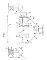
- the milling unit is shown with 1 or 1 '.
- the milling cutter 2 is attached with its shaft 3 om a holding head 4.
- Shank 3 with milling cutter 2 are driven by a drive motor 5.
- the holder 4 of the shaft is fastened in an assembly guide 6 and displaced in the direction of the arrow 7 relative to a workpiece holder 8 bar, which receives the workpiece 9, for example a rung frame bar, with a T-shaped cross section.
- the workpiece 9 has legs 10 and 11 into which the milling cutter mills the mitres 12, 13.
- the workpiece 9 is positioned in a clamping device 14, 15.
- a clamping pressure is exerted against the clamping device via a clamping device 16.
- the workpiece holder 8 is then pivoted about an axis of rotation 17 in the direction of the arrow 18.
- the workpiece 9 comes into engagement with a nuting unit 19, the nuting tool 20 of which mills a plating 21 into the workpiece 9.
- the groove unit 19 is arranged in a height-adjustable manner in the frame of the overall device.
- the method of operation of the device according to the invention is as follows: the milling unit 1 is shifted to the right in the direction of arrow 7 in the schematic illustration according to FIG. 1 and mills a miter 12 into the workpiece 9 during this movement. This movement process is indicated at the position denoted by 1 ' completed. Subsequently, the workpiece holder 8 is pivoted with the workpiece 9 about the rotation axis 17 in the direction of arrow 18 to 180 0th With a partial pivoting by 90 °, the workpiece 9 in the workpiece holder 8 engages with the grooving tool 20, which mills a plate 21 in the workpiece.
- the workpiece 9 with the workpiece holder is pivoted further into the position 8 'and thus assumes a position pivoted by 180 ° with respect to the starting position.
- the milling unit 1 is shifted from the position 1 'from right to left in the drawing, the milling tool 2 milling the second miter 13 and the milling unit 1 finally assuming the starting position on the left in the drawing.
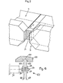
- the finished workpiece 9 provided with the two opposing mitres 12, 13 and the plating 21 is shown in a perspective view in FIG. 2.
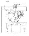
- the structure of the device according to the invention is shown in more detail in FIGS. 3, 4 and 5.
- the machine frame 22 of the device consists of a lower part 23, which receives the grooving unit 19, and an upper part 24, which receives the milling unit 1 and the workpiece holder 8 with workpiece 9.
- the nut unit 19 which also includes the nut drive includes, fixed in a frame part 25 which is suspended from an intermediate floor 26 on the machine frame.
- the height adjustment of the nut unit 19 is carried out by means of height adjustment devices 27, 27.
- the height adjustment of the nut tool 20 or the nut unit 19 can, however, be carried out in any other manner. Irrespective of and in addition to the height adjustment, the grooving tool can be adjusted to a small extent laterally in order to carry out a correction movement in the assignment to the milling tool, as indicated by arrow 28.
- the lower part 23 and the upper part 24 of the device consist of vertical and horizontal supports which are closed to form a frame and are enclosed by a housing 29 which is open laterally and at the front in the region of the upper part 23.
- Carriers 30, 31 are fastened on the upper side of the upper part 24 and receive bearing blocks 32, 33 for guide rods 34, 35, on which a carrier plate 36, which receives the milling cutter assembly 1, can be displaced in the direction of arrow 39 (FIG. 3). With the help of a handle 37 on the milling unit 1, the milling unit with milling tool 2 is moved by the operator over the entire depth 1-1 'of the device.
- a height adjustment device 38 is fastened to the carrier plate 36, which consists, for example, of a screw bolt 40 which is fixedly connected to the carrier plate 36 and a threaded adjusting wheel 41 which is vertically movable thereon, the height movement of which is transmitted to the milling unit 1.
- the workpiece holder 8 with the workpiece 9 is fastened on the frame or on the housing 29 so as to be adjustable in height about an axis 17.
- Cylindrical rotary members 44, 45 are mounted on pins 42, 43 fixed to the housing, with the outer ends of which actuating levers 46, 47 are fastened and to which the workpiece holding device 8 is connected.
- Both rotary members 44, 45 are of identical design and each take up a receiving plate 48 which is fixedly connected to the rotary member in question.
- the vertical mounting plate 48 has a horizontal leg 49, through which a bolt 50 is guided, which is provided, for example, with a screw thread, to which a thread adjusting wheel 51 is connected in a height-adjustable manner.
- the bolt 50 is horizontal Carrier plate 52 connected, which receives a second, movable receiving plate 53.
- the workpiece 9 is arranged between the two mounting plates 48 and 53.
- a slide acting against the receiving plate 53 designates a slide acting against the receiving plate 53, which is guided in a guide member 55 which is connected to the carrier plate 52 via a flange 56.
- a lever arm 57 is fastened, which is articulated to an intermediate lever 58 articulated on the slide 54, such that when the lever 57 is actuated about the pivot point 59, the slide 54 is pressed against the movable mounting plate 53 is and thus the workpiece 9 is fixed between the mounting plate 48 and 53 by clamping pressure.
- the workpieces can optionally also be clamped pneumatically, namely via pressure cylinders.
- the workpiece mounting plates 48 and 53 are cut out and divided in accordance with the shape of the milling tool 2 and at 62 in accordance with the shape of the grooving tool 20, they represent splinter protection.
Landscapes
- Life Sciences & Earth Sciences (AREA)
- Engineering & Computer Science (AREA)
- Wood Science & Technology (AREA)
- Mechanical Engineering (AREA)
- Forests & Forestry (AREA)
- Milling Processes (AREA)
- Dovetailed Work, And Nailing Machines And Stapling Machines For Wood (AREA)
- Door And Window Frames Mounted To Openings (AREA)
Priority Applications (1)
| Application Number | Priority Date | Filing Date | Title |
|---|---|---|---|
| AT85107968T ATE37819T1 (de) | 1984-07-05 | 1985-06-27 | Verfahren und vorrichtung zum fraesen und nuten von rahmenteilen aus holz. |
Applications Claiming Priority (2)
| Application Number | Priority Date | Filing Date | Title |
|---|---|---|---|
| DE3424680 | 1984-07-05 | ||
| DE3424680A DE3424680A1 (de) | 1984-07-05 | 1984-07-05 | Verfahren und vorrichtung zum fraesen und nuten von rahmenteilen aus holz |
Publications (2)
| Publication Number | Publication Date |
|---|---|
| EP0167112A1 true EP0167112A1 (fr) | 1986-01-08 |
| EP0167112B1 EP0167112B1 (fr) | 1988-10-12 |
Family
ID=6239855
Family Applications (1)
| Application Number | Title | Priority Date | Filing Date |
|---|---|---|---|
| EP85107968A Expired EP0167112B1 (fr) | 1984-07-05 | 1985-06-27 | Procédé et appareil pour fraiser et rainurer des parties d'un cadre en bois |
Country Status (4)
| Country | Link |
|---|---|
| US (1) | US4632165A (fr) |
| EP (1) | EP0167112B1 (fr) |
| AT (1) | ATE37819T1 (fr) |
| DE (2) | DE3424680A1 (fr) |
Families Citing this family (4)
| Publication number | Priority date | Publication date | Assignee | Title |
|---|---|---|---|---|
| DE3609331C1 (de) * | 1986-03-20 | 1986-12-04 | Erwin 7261 Gechingen Jenkner | Saege- und Bohrmaschine zum Aufteilen und Bohren plattenfoermiger Werkstuecke |
| US4934421A (en) * | 1989-08-01 | 1990-06-19 | Colonial Saw Company, Inc. | Wood cutting machine |
| US5305812A (en) * | 1993-03-05 | 1994-04-26 | Ferencsik Robert P | Programmable woodworking dovetail machine |
| GB2552355A (en) * | 2016-07-20 | 2018-01-24 | Mighton Products Ltd | Cross joint milling machine |
Citations (2)
| Publication number | Priority date | Publication date | Assignee | Title |
|---|---|---|---|---|
| US3735787A (en) * | 1970-10-28 | 1973-05-29 | Platt E A | Stud and dado cutter |
| US3837384A (en) * | 1972-03-29 | 1974-09-24 | Huebel & Platzer Maschinenbau | System for cutting splines in boards |
Family Cites Families (2)
| Publication number | Priority date | Publication date | Assignee | Title |
|---|---|---|---|---|
| US1200836A (en) * | 1915-03-22 | 1916-10-10 | Harzer Holzwaren Fabrik Gebr Lohoff | Wood-turning machine. |
| DE869555C (de) * | 1951-05-08 | 1953-03-05 | Ferdinand Fromm | Vorrichtung und Verfahren zum Ausklinken von stabfoermigen Werk-stuecken, insbesondere von Fenstersprossenkreuze ergebenden Holzstaeben |
-
1984
- 1984-07-05 DE DE3424680A patent/DE3424680A1/de active Granted
-
1985
- 1985-06-27 AT AT85107968T patent/ATE37819T1/de not_active IP Right Cessation
- 1985-06-27 DE DE8585107968T patent/DE3565490D1/de not_active Expired
- 1985-06-27 EP EP85107968A patent/EP0167112B1/fr not_active Expired
- 1985-07-03 US US06/751,532 patent/US4632165A/en not_active Expired - Fee Related
Patent Citations (2)
| Publication number | Priority date | Publication date | Assignee | Title |
|---|---|---|---|---|
| US3735787A (en) * | 1970-10-28 | 1973-05-29 | Platt E A | Stud and dado cutter |
| US3837384A (en) * | 1972-03-29 | 1974-09-24 | Huebel & Platzer Maschinenbau | System for cutting splines in boards |
Also Published As
| Publication number | Publication date |
|---|---|
| ATE37819T1 (de) | 1988-10-15 |
| DE3424680A1 (de) | 1986-02-06 |
| US4632165A (en) | 1986-12-30 |
| DE3424680C2 (fr) | 1989-06-15 |
| DE3565490D1 (en) | 1988-11-17 |
| EP0167112B1 (fr) | 1988-10-12 |
Similar Documents
| Publication | Publication Date | Title |
|---|---|---|
| DE3035451C2 (fr) | ||
| DE3220026C2 (fr) | ||
| CH629407A5 (de) | Werkzeugmaschine. | |
| EP0237615A1 (fr) | Machine à scier et à percer pour le débitage et l'alésage de pièces en plaques | |
| EP0157728A1 (fr) | Machine à tourner | |
| EP0565050A1 (fr) | Tête de fraisage | |
| DE2636986C3 (de) | Drehmaschine | |
| EP0292864B1 (fr) | Machine pour travailler le bois | |
| EP0167112B1 (fr) | Procédé et appareil pour fraiser et rainurer des parties d'un cadre en bois | |
| EP0058369B1 (fr) | Dispositif d'avance pour les machines-outils pour l'usinage du bois | |
| DE8100802U1 (de) | "drehbank mit mehreren werkzeugschlitten" | |
| EP0787560A1 (fr) | Dispositif d'usinage des barres, des profilés et similaire | |
| EP0483499A2 (fr) | Machine pour l'usinage des extrémités de châssis de fenêtres | |
| DE2328439C3 (de) | Schwenkbarer Werkstück-Aufspanntisch für Werkzeugmaschinen, insbesondere für Universal-Fräsmaschinen | |
| DE2846591A1 (de) | Fensterhoelzer-bearbeitungsmaschine | |
| DE3914008A1 (de) | Vorrichtung zum herstellen und bearbeiten von werkstuecken beliebiger geometrie | |
| DE2749546A1 (de) | Fensterhoelzer-bearbeitungsmaschine | |
| DE2058005A1 (de) | Werkzeugmaschine | |
| DE3717411C2 (fr) | ||
| DE4401044B4 (de) | Hobelmaschine | |
| DE3933863A1 (de) | Schleifmaschine | |
| DE3100826A1 (de) | Fraesmaschine mit in mehreren koordinaten beweglichen spindelkoepfen | |
| DE4413483A1 (de) | Aufsatzgerät für eine Werkzeugschleifmaschine | |
| DE2321617C3 (de) | Vorrichtung zum spanabhebenden Entgraten und Formen der Zahnenden von Zahnrädern o.dgl | |
| DE2741123C2 (de) | Werkzeug zum Anschrägen der beim Stanzen entstandenen Werkstückskanten auf einer Koordinaten-Stanzmaschine |
Legal Events
| Date | Code | Title | Description |
|---|---|---|---|
| PUAI | Public reference made under article 153(3) epc to a published international application that has entered the european phase |
Free format text: ORIGINAL CODE: 0009012 |
|
| AK | Designated contracting states |
Designated state(s): AT BE CH DE FR GB IT LI NL SE |
|
| 17P | Request for examination filed |
Effective date: 19860412 |
|
| 17Q | First examination report despatched |
Effective date: 19870611 |
|
| GRAA | (expected) grant |
Free format text: ORIGINAL CODE: 0009210 |
|
| AK | Designated contracting states |
Kind code of ref document: B1 Designated state(s): AT BE CH DE FR GB IT LI NL SE |
|
| PG25 | Lapsed in a contracting state [announced via postgrant information from national office to epo] |
Ref country code: SE Effective date: 19881012 Ref country code: NL Effective date: 19881012 Ref country code: GB Free format text: LAPSE BECAUSE OF NON-PAYMENT OF DUE FEES Effective date: 19881012 Ref country code: BE Effective date: 19881012 |
|
| REF | Corresponds to: |
Ref document number: 37819 Country of ref document: AT Date of ref document: 19881015 Kind code of ref document: T |
|
| REF | Corresponds to: |
Ref document number: 3565490 Country of ref document: DE Date of ref document: 19881117 |
|
| ET | Fr: translation filed | ||
| ITF | It: translation for a ep patent filed |
Owner name: MODIANO & ASSOCIATI S.R.L. |
|
| NLV1 | Nl: lapsed or annulled due to failure to fulfill the requirements of art. 29p and 29m of the patents act | ||
| GBV | Gb: ep patent (uk) treated as always having been void in accordance with gb section 77(7)/1977 [no translation filed] | ||
| PLBE | No opposition filed within time limit |
Free format text: ORIGINAL CODE: 0009261 |
|
| STAA | Information on the status of an ep patent application or granted ep patent |
Free format text: STATUS: NO OPPOSITION FILED WITHIN TIME LIMIT |
|
| 26N | No opposition filed | ||
| PGFP | Annual fee paid to national office [announced via postgrant information from national office to epo] |
Ref country code: DE Payment date: 19900517 Year of fee payment: 6 |
|
| PGFP | Annual fee paid to national office [announced via postgrant information from national office to epo] |
Ref country code: FR Payment date: 19900613 Year of fee payment: 6 |
|
| ITTA | It: last paid annual fee | ||
| PG25 | Lapsed in a contracting state [announced via postgrant information from national office to epo] |
Ref country code: FR Effective date: 19920228 |
|
| PG25 | Lapsed in a contracting state [announced via postgrant information from national office to epo] |
Ref country code: DE Effective date: 19920401 |
|
| REG | Reference to a national code |
Ref country code: FR Ref legal event code: ST |
|
| PGFP | Annual fee paid to national office [announced via postgrant information from national office to epo] |
Ref country code: AT Payment date: 19930614 Year of fee payment: 9 |
|
| PGFP | Annual fee paid to national office [announced via postgrant information from national office to epo] |
Ref country code: CH Payment date: 19930628 Year of fee payment: 9 |
|
| PG25 | Lapsed in a contracting state [announced via postgrant information from national office to epo] |
Ref country code: AT Effective date: 19940627 |
|
| PG25 | Lapsed in a contracting state [announced via postgrant information from national office to epo] |
Ref country code: LI Effective date: 19940630 Ref country code: CH Effective date: 19940630 |
|
| REG | Reference to a national code |
Ref country code: CH Ref legal event code: PL |