EP1279465B1 - Moulurière et procédé de positionnement d'au moins une broche de la moulurière - Google Patents
Moulurière et procédé de positionnement d'au moins une broche de la moulurière Download PDFInfo
- Publication number
- EP1279465B1 EP1279465B1 EP02016172A EP02016172A EP1279465B1 EP 1279465 B1 EP1279465 B1 EP 1279465B1 EP 02016172 A EP02016172 A EP 02016172A EP 02016172 A EP02016172 A EP 02016172A EP 1279465 B1 EP1279465 B1 EP 1279465B1
- Authority
- EP
- European Patent Office
- Prior art keywords
- spindle
- display
- profile
- spindles
- moulding machine
- Prior art date
- Legal status (The legal status is an assumption and is not a legal conclusion. Google has not performed a legal analysis and makes no representation as to the accuracy of the status listed.)
- Expired - Fee Related
Links
Images


Classifications
-
- B—PERFORMING OPERATIONS; TRANSPORTING
- B23—MACHINE TOOLS; METAL-WORKING NOT OTHERWISE PROVIDED FOR
- B23Q—DETAILS, COMPONENTS, OR ACCESSORIES FOR MACHINE TOOLS, e.g. ARRANGEMENTS FOR COPYING OR CONTROLLING; MACHINE TOOLS IN GENERAL CHARACTERISED BY THE CONSTRUCTION OF PARTICULAR DETAILS OR COMPONENTS; COMBINATIONS OR ASSOCIATIONS OF METAL-WORKING MACHINES, NOT DIRECTED TO A PARTICULAR RESULT
- B23Q17/00—Arrangements for observing, indicating or measuring on machine tools
- B23Q17/22—Arrangements for observing, indicating or measuring on machine tools for indicating or measuring existing or desired position of tool or work
-
- B—PERFORMING OPERATIONS; TRANSPORTING
- B23—MACHINE TOOLS; METAL-WORKING NOT OTHERWISE PROVIDED FOR
- B23Q—DETAILS, COMPONENTS, OR ACCESSORIES FOR MACHINE TOOLS, e.g. ARRANGEMENTS FOR COPYING OR CONTROLLING; MACHINE TOOLS IN GENERAL CHARACTERISED BY THE CONSTRUCTION OF PARTICULAR DETAILS OR COMPONENTS; COMBINATIONS OR ASSOCIATIONS OF METAL-WORKING MACHINES, NOT DIRECTED TO A PARTICULAR RESULT
- B23Q1/00—Members which are comprised in the general build-up of a form of machine, particularly relatively large fixed members
- B23Q1/0009—Energy-transferring means or control lines for movable machine parts; Control panels or boxes; Control parts
-
- B—PERFORMING OPERATIONS; TRANSPORTING
- B27—WORKING OR PRESERVING WOOD OR SIMILAR MATERIAL; NAILING OR STAPLING MACHINES IN GENERAL
- B27C—PLANING, DRILLING, MILLING, TURNING OR UNIVERSAL MACHINES FOR WOOD OR SIMILAR MATERIAL
- B27C5/00—Machines designed for producing special profiles or shaped work, e.g. by rotary cutters; Equipment therefor
- B27C5/02—Machines with table
-
- B—PERFORMING OPERATIONS; TRANSPORTING
- B27—WORKING OR PRESERVING WOOD OR SIMILAR MATERIAL; NAILING OR STAPLING MACHINES IN GENERAL
- B27F—DOVETAILED WORK; TENONS; SLOTTING MACHINES FOR WOOD OR SIMILAR MATERIAL; NAILING OR STAPLING MACHINES
- B27F1/00—Dovetailed work; Tenons; Making tongues or grooves; Groove- and- tongue jointed work; Finger- joints
- B27F1/02—Making tongues or grooves, of indefinite length
- B27F1/06—Making tongues or grooves, of indefinite length simultaneously along opposite edges of a board
-
- B—PERFORMING OPERATIONS; TRANSPORTING
- B27—WORKING OR PRESERVING WOOD OR SIMILAR MATERIAL; NAILING OR STAPLING MACHINES IN GENERAL
- B27M—WORKING OF WOOD NOT PROVIDED FOR IN SUBCLASSES B27B - B27L; MANUFACTURE OF SPECIFIC WOODEN ARTICLES
- B27M1/00—Working of wood not provided for in subclasses B27B - B27L, e.g. by stretching
- B27M1/08—Working of wood not provided for in subclasses B27B - B27L, e.g. by stretching by multi-step processes
-
- Y—GENERAL TAGGING OF NEW TECHNOLOGICAL DEVELOPMENTS; GENERAL TAGGING OF CROSS-SECTIONAL TECHNOLOGIES SPANNING OVER SEVERAL SECTIONS OF THE IPC; TECHNICAL SUBJECTS COVERED BY FORMER USPC CROSS-REFERENCE ART COLLECTIONS [XRACs] AND DIGESTS
- Y10—TECHNICAL SUBJECTS COVERED BY FORMER USPC
- Y10T—TECHNICAL SUBJECTS COVERED BY FORMER US CLASSIFICATION
- Y10T29/00—Metal working
- Y10T29/51—Plural diverse manufacturing apparatus including means for metal shaping or assembling
- Y10T29/5104—Type of machine
- Y10T29/5115—Planer
-
- Y—GENERAL TAGGING OF NEW TECHNOLOGICAL DEVELOPMENTS; GENERAL TAGGING OF CROSS-SECTIONAL TECHNOLOGIES SPANNING OVER SEVERAL SECTIONS OF THE IPC; TECHNICAL SUBJECTS COVERED BY FORMER USPC CROSS-REFERENCE ART COLLECTIONS [XRACs] AND DIGESTS
- Y10—TECHNICAL SUBJECTS COVERED BY FORMER USPC
- Y10T—TECHNICAL SUBJECTS COVERED BY FORMER US CLASSIFICATION
- Y10T29/00—Metal working
- Y10T29/51—Plural diverse manufacturing apparatus including means for metal shaping or assembling
- Y10T29/5122—Plural diverse manufacturing apparatus including means for metal shaping or assembling with means to feed work during tool contact
-
- Y—GENERAL TAGGING OF NEW TECHNOLOGICAL DEVELOPMENTS; GENERAL TAGGING OF CROSS-SECTIONAL TECHNOLOGIES SPANNING OVER SEVERAL SECTIONS OF THE IPC; TECHNICAL SUBJECTS COVERED BY FORMER USPC CROSS-REFERENCE ART COLLECTIONS [XRACs] AND DIGESTS
- Y10—TECHNICAL SUBJECTS COVERED BY FORMER USPC
- Y10T—TECHNICAL SUBJECTS COVERED BY FORMER US CLASSIFICATION
- Y10T29/00—Metal working
- Y10T29/51—Plural diverse manufacturing apparatus including means for metal shaping or assembling
- Y10T29/5136—Separate tool stations for selective or successive operation on work
-
- Y—GENERAL TAGGING OF NEW TECHNOLOGICAL DEVELOPMENTS; GENERAL TAGGING OF CROSS-SECTIONAL TECHNOLOGIES SPANNING OVER SEVERAL SECTIONS OF THE IPC; TECHNICAL SUBJECTS COVERED BY FORMER USPC CROSS-REFERENCE ART COLLECTIONS [XRACs] AND DIGESTS
- Y10—TECHNICAL SUBJECTS COVERED BY FORMER USPC
- Y10T—TECHNICAL SUBJECTS COVERED BY FORMER US CLASSIFICATION
- Y10T409/00—Gear cutting, milling, or planing
- Y10T409/30—Milling
- Y10T409/306664—Milling including means to infeed rotary cutter toward work
- Y10T409/307224—Milling including means to infeed rotary cutter toward work with infeed control means energized in response to activator stimulated by condition sensor
- Y10T409/30728—In response to cutter condition
Definitions
- the invention relates to a molding machine according to the preamble of claim 1 and a method for adjusting at least one of the spindles of such a molding machine according to the preamble of claim 10.
- the workpieces are processed on their passage on several sides with tools sitting on the spindles.
- the spindles must be adjusted to the dimensions of the workpiece and to the profile to be produced on this workpiece. It is known to store the profile data and the measured tool data in a memory. From these stored profile and tool data, the set values for the spindles for generating the desired profile are calculated by a program.
- the invention has the object of providing the generic molding machine and the generic method in such a way that the adjustment of the spindle provided adjustment is easy and inexpensive.
- the spindle is set relative to the machine-side reference point in a predetermined position.
- the associated position value is displayed on the display device.
- the position value of the spindle is stored as the actual value in the data memory. If the spindle is to be set again in this position, the stored actual value is retrieved from the data memory and displayed again on the display device.
- the operator of the molding machine according to the invention must then only adjust the spindle such that the actual value indicated on the display device coincides with the desired value also displayed on the display device.
- the display device can also be designed so that when retrieving the setpoint from the data memory, the difference value is displayed for the current actual position of the spindle.
- the operator of the molding machine according to the invention must adjust the spindle in this case so that the displayed difference value is brought to zero.
- the moulder is used for machining workpieces made of wood, plastic and the like, which are transported for processing on their sides by the moulder in a known manner.
- the molding machine has a transport path 1, on which the workpieces (not shown) are transported. During their transport through the moulder, these workpieces rest on a stop 2, which extends over the length of the molding machine and is interrupted in the region of lateral spindles.
- the workpieces are transported in Fig. 1 from right to left on the transport path 1.
- transport rollers 3 are provided, which rest on the workpiece and are rotatably driven.
- the transport rollers 3 are suspended from a transport bar 4, which is located above the transport path 1 at a distance.
- the workpieces are first processed in their passage through the molding machine with a tool 5, which sits on a located in the area below the transport path 1 horizontal dressing spindle. With this tool 5, the bottom of the workpiece is processed, in particular planed.
- the transport path 1 has a corresponding opening for the passage of the tool 5.
- the moulder In the transport direction at a distance behind the lower dressing spindle, the moulder is provided with a vertical spindle 6, on which a tool 7 is seated, with which the right in the transport direction side of the workpieces is processed.
- the spindle 6 is seated on a cross slide 8, which preferably extends perpendicular to the transport direction of the workpieces through the molding machine. With the cross slide 8, the tool 7 can be moved transversely, preferably perpendicular to the transport direction.
- a tool 9 which is located on the left in the transport direction of the workpieces to be processed.
- This tool 9 is non-rotatably mounted on a vertical spindle.
- the tool 9 together with the spindle is mounted on a cross slide 10, which can be moved transversely, preferably perpendicular to the transport direction of the workpieces.
- the two cross slides 8, 10 are spaced from each other.
- the tops of the cross slide 8, 10 are advantageously in a plane with the top of the transport path 1, so that the workpieces can be conveyed smoothly in the transition from the transport path 1 to the cross slide 8, 10.
- the tops of the cross slide 8, 10 but can also be lower. Then separate table tops form the transport path 1 in this area.
- a tool 11 which is non-rotatably mounted on a horizontal spindle, which is arranged in the region above the transport path 1 and the workpieces. With the tool 11, the top of the workpiece is processed, for example, planed straight.
- the moulder may have other subsequent tools, such as further lower spindles.
- the tools 5, 7, 9, 11 may also be profile tools, i. they carry profile knives, which have the desired profiling. This profiled the corresponding sides of the workpiece. It is also possible, depending on the application on one spindle planing tools and other spindles profile tools to arrange so that the corresponding sides of the workpiece are planed or profiled straight.
- the workpieces After passing through the moulder, the workpieces have been processed on their sides.
- the workpieces are moved past with a small distance one behind the other on the various tools 5, 7, 9, 11, which make the appropriate processing on the workpieces.
- the molding machine is provided with an adjustment device which has display devices 12 for the various axis adjustments (FIG. 2). All display devices 12 are connected to a data memory 13, in the manner to be described, the actual dimensions of all spindles 12 under a certain program number or a program or profile name. If the molding machine is to be set again for the corresponding workpiece profile, then the adjustment data stored in the memory 13 under the corresponding program number or the corresponding program or profile name are called up and transmitted to the individual display devices 12.
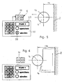
- Fig. 3 shows the workpiece to be machined 14, which is transported along the stop rule 2 in the transport direction 15 through the molding machine.
- the workpiece 14 is to be processed with the tool 9, which sits on the spindle 16 rotatably on its left in the transport direction 15 side.
- the spindle 16 is in this case set with respect to the stop rule 2 that it has the distance 150 mm from the fence rule 2.
- the workpiece 14 has the width dimension 17 prior to machining by the tool 9. After machining by the tool 9, the workpiece 14 only has the smaller width dimension 18.
- the indicating device 12 assigned to the spindle 16 sits on the corresponding adjusting spindle 25 for the tool spindle 16 and has a display 19, in which the distance of the spindle 16 from the stop rule 2 is preferably displayed electronically.
- the display device 12 is drivingly connected in a known manner via a sleeve 26 with the adjusting spindle 25 and determined by the rotational movement of the adjusting spindle 25, taking into account the spindle pitch, for example, according to the principle of a rotary encoder the distance of the machine spindle 9 of the fence 2, which is displayed in the display 19.
- the settings are stored in the data memory 13 under a program number, a program or profile name in a defined sequence.
- the data is stored under the name "profile 1".
- the memory button 21 is pressed for this purpose.
- Fig. 4 shows the case that with the tool 9 on the spindle 16, a new workpiece 14 with a profile 2 with a smaller width 17 than in the embodiment of FIG. 3 should be processed.
- the spindle 16 is adjusted so that it has, for example, the distance 75 mm from the fence 2 of the moulder. This set dimension appears in the display 19 of the display device 12. All spindles of the moulder are set to the new workpiece 14 with the profile 2 with the width dimension 17, the corresponding positions of the respective spindles of the molding machine appear in the display 19 of the respective display device 12.
- the settings of the various spindles in the defined order are transmitted to the data memory 13 by pressing the memory button 21 of the input device 20 and stored in the exemplary embodiment under the name "Profile 2".
- the position data of pressure elements are advantageously detected and stored in the data memory 13.
- the Anyaketti are in a known manner in front of and behind on the arranged spindle corresponding tool and lie on the workpiece 14.
- the pressure elements are adjusted relative to the tool in order to exert an optimal pressure action on the workpiece 14.
- the pressure elements are also advantageous associated with display devices 12, with which in the same manner as in the spindles, the position of the pressure elements is detected.
- One of these display devices 12 ' can be seen in Fig. 1, with which the position of the one, the upper horizontal spindle associated (not shown) Anyakettis is detected.
- This display device 12 ' is also connected to the data memory 13.
- FIGS. 5 and 6 show the case that the setting data for the spindles of the molding machine are to be retrieved from the data memory 13 in order to produce the profile 1 on the workpiece 14.
- the value 75 is displayed, from which it follows that the spindle 16 is arranged for the tool 9 at a distance of 75 mm from the stop rule 2 of the molding machine.
- the name "profile 1" is first set on the input device 20 in a display 23 of the input device 20 and then the call key 22 is pressed.
- the setting data stored in the data memory 13 under the name "profile 1" are transmitted in the defined order to the respective display devices 12 and displayed in the upper field of the display 19.
- the spindle 16 is arranged in the production of the profile 1 at a distance of 150 mm to the stop rule 2. Accordingly, this value is displayed in the upper display panel of the display 19 of the associated display device 12. In the lower display panel of the display 19 is still the instantaneous value for the distance of the spindle 16 is indicated by the stop rule 2, which is 75 mm in the embodiment.
- the operator of the moulder must now adjust the spindle 16 so far until the value 150 appears in the lower display field of the display 19 (FIG. 6). Then, the spindle 16 has the distance of 150 mm from the stop rule. 2
- the adjustment data stored under the name "profile 1" are also transmitted to the respective display devices 12 to the respective spindles in this way.
- the operator of the molding machine then only has to ensure that the same values are indicated in the two display fields of the respective display devices.
- the corresponding data from the data memory 13 are also transmitted to the pressure elements associated with the display devices 12 '. If the setpoint deviates from the actual value, the corresponding pressure element is adjusted so that the displayed actual value coincides with the setpoint.
- a trial run of a workpiece is carried out. If, for example, the circle diameter of the tool 9 has changed in the time between the storage of the setting data and the renewed retrieval, for example by regrinding the cutting blade, the required adjustment of the respective spindle can be determined and made after the trial run.
- the new actual data are then, as has been explained with reference to FIGS. 3 and 4, transferred to the memory 13 by pressing the memory button 21 of the input device 20 and the corresponding designation.
- the moulder can be adjusted in the manner described using the adjustment with very little effort and easy on the workpiece profile to be produced.
- the setting data stored in the data memory 13 are actual data during the acquisition the retrieval from memory as target data in the display 19 of the respective display device 12 are displayed.
- the operator of the moulder only has to adjust the respective spindle so that the actual position of the spindle coincides with the desired position retrieved from the data memory 13. In the display with the two display fields, this can be monitored very easily. If the profile produced on the workpiece 14 after its trial pass through the molding machine does not coincide with the nominal profile, because, for example, the tools have been reground, the adjustment of the spindles is corrected accordingly.
- the new setting dimensions are then in turn transmitted in the manner described to the data memory as actual dimensions.
- the moulder can be set with the mechanical display devices in the usual way according to established setting and tool data or even a wood pattern.
- the display device 12, 12 ' the display 19 with the two display fields in which the actual and the desired value are displayed.
- the display device 12, 12 ' can also be designed so that when retrieving the setpoints from the data memory 13 in the display 19, only the difference value is displayed for the current actual position. The operator of the moulder must then make the adjustment so that the difference value is brought to zero.
- the display device 12, 12 displays in its display 19 only the actual or the desired value.
- a switch (not shown) can be used to switch between the two displayed values. Even then, the various spindles and adjustable elements can be easily and reliably adjusted to the required position.
- the new actual position is stored in the manner described as a new setpoint in the memory 13.
Landscapes
- Engineering & Computer Science (AREA)
- Life Sciences & Earth Sciences (AREA)
- Mechanical Engineering (AREA)
- Wood Science & Technology (AREA)
- Forests & Forestry (AREA)
- Machine Tool Sensing Apparatuses (AREA)
- Injection Moulding Of Plastics Or The Like (AREA)
- Making Paper Articles (AREA)
Claims (15)
- Moulurière pour l'usinage de pièces à usiner (14) en bois, plastique ou analogues, équipée d'au moins une bande transporteuse (1) pour les pièces à usiner et d'outils (5, 7, 9, 11), qui sont montés à rotation sur les broches (6, 16), qui peuvent être positionnées et reliées en entraînement par des éléments d'ajustement (25), de préférence des broches de réglage,
caractérisée en ce que les éléments d'ajustement (25) sont couplés à des dispositifs d'affichage (12) affichant la position des broches (6, 16) par rapport à un point de référence (2) côté machine, qui sont reliés à au moins une mémoire de données (13), dans laquelle les données de position des broches (6, 16) peuvent être stockées comme valeur effective pour le profil à fabriquer sous un nom associé à ce profil et peuvent être extraites de celle-ci comme valeur de consigne pour un nouveau positionnement de ce profil. - Moulurière selon la revendication 1, caractérisée en ce que les dispositifs d'affichage (12) sont montés à rotation sur les éléments d'ajustement.
- Moulurière selon la revendication 1 ou 2, caractérisée en ce que le dispositif d'affichage (12) présente au moins un affichage (19) présentant avantageusement deux fenêtres d'affichage.
- Moulurière selon l'une des revendications 1 à 3, caractérisée en ce que la mémoire de données (13) présente au moins un périphérique d'entrée (20) présentant avantageusement au moins un affichage (23).
- Moulurière selon la revendication 4, caractérisée en ce que le périphérique d'entrée (20) est équipé d'un clavier alphanumérique (24).
- Moulurière selon l'une des revendications 1 à 5, caractérisée en ce qu'au moins une des broches (6, 16) est positionnée transversalement à la direction de transport des pièces à usiner (14).
- Moulurière selon la revendication 6, caractérisée en ce que la broche (6, 16) prévue avantageusement sur une coulisse transversale (8, 10) peut être positionnée transversalement à son axe.
- Moulurière selon la revendication 6 ou 7, caractérisée en ce que la broche (6, 16) peut être positionnée dans sa direction axiale.
- Moulurière selon l'une des revendications 1 à 8, qui est équipée d'éléments presseurs, qui peuvent être positionnés par rapport à la broche associée, caractérisée en ce que, en vue du positionnement d'au moins un élément presseur, au moins un dispositif d'affichage (12') est prévu, qui est relié à la mémoire de données (13).
- Procédé de positionnement d'au moins une des broches (6, 16) d'une moulurière selon l'une des revendications 1 à 9, dans lequel la broche (6, 16) est positionnée par rapport à un point de référence (2) côté machine,
caractérisé en ce que la broche (6, 16) est positionnée dans une position désirée par rapport au point de référence (2) côté machine et les données de position de la broche (6, 16) sont stockées comme valeur effective pour le profil à fabriquer sous un nom associé à ce profil dans une mémoire de données (13), à partir de laquelle la valeur effective stockée est extraite comme valeur de consigne pour un nouveau positionnement de ce profil en vue du positionnement de la broche (6, 16). - Procédé selon la revendication 10, caractérisé en ce que la valeur de consigne est affichée sur un affichage (19) d'un dispositif d'affichage (12) et la broche (6, 16) est déplacée de sa position respective de sorte que la valeur effective affichée sur l'affichage (19) correspond à la valeur de consigne.
- Procédé selon la revendication 10 ou 11, caractérisé en ce que la broche (6, 16) est positionnée dans une position nécessaire pour le profil à fabriquer à partir d'une pièce à usiner (14) et la valeur effective associée est stockée dans la mémoire de données (13) sous un nom associé à ce profil.
- Procédé selon l'une des revendications 10 à 12, caractérisé en ce que toutes les broches (6, 16) de la moulurière sont positionnées dans une position désirée par rapport au point de référence (2) côté machine et en ce que la valeur effective respective des broches (6, 16) est stockée dans la mémoire de données (13).
- Procédé selon la revendication 10, caractérisé en ce que la valeur de consigne est affichée sur l'affichage (19) du dispositif d'affichage (12) comme valeur différentielle par rapport à la valeur effective instantanée de la broche (6, 16) et la broche (6, 16) est déplacée de sorte que la valeur différentielle atteint la valeur zéro.
- Procédé selon l'une des revendications 10 à 14, caractérisé en ce qu'au moins un élément presseur est positionné dans une position désirée par rapport à l'outil associé (5, 7, 9) et la valeur effective correspondant à cette position est stockée dans la mémoire de données (13), à partir de laquelle la valeur effective stockée est extraite comme valeur de consigne pour un nouveau positionnement de l'élément presseur dans la même position.
Applications Claiming Priority (2)
| Application Number | Priority Date | Filing Date | Title |
|---|---|---|---|
| DE10136767A DE10136767A1 (de) | 2001-07-27 | 2001-07-27 | Kehlmaschine sowie Verfahren zur Einstellung wenigstens einer der Spindeln der Kehlmaschine |
| DE10136767 | 2001-07-27 |
Publications (2)
| Publication Number | Publication Date |
|---|---|
| EP1279465A1 EP1279465A1 (fr) | 2003-01-29 |
| EP1279465B1 true EP1279465B1 (fr) | 2007-09-12 |
Family
ID=7693382
Family Applications (1)
| Application Number | Title | Priority Date | Filing Date |
|---|---|---|---|
| EP02016172A Expired - Fee Related EP1279465B1 (fr) | 2001-07-27 | 2002-07-20 | Moulurière et procédé de positionnement d'au moins une broche de la moulurière |
Country Status (4)
| Country | Link |
|---|---|
| US (1) | US6695021B2 (fr) |
| EP (1) | EP1279465B1 (fr) |
| DE (2) | DE10136767A1 (fr) |
| TW (1) | TW564211B (fr) |
Families Citing this family (4)
| Publication number | Priority date | Publication date | Assignee | Title |
|---|---|---|---|---|
| EP1957688A2 (fr) | 2005-11-22 | 2008-08-20 | Genus, Inc. | Appareil de depot de couche atomique (ald) a tranche unique et a ecoulement symetrique de petit volume |
| ES2381837T3 (es) | 2008-08-14 | 2012-06-01 | Homag Holzbearbeitungssysteme Ag | Máquina reajustable, especialmente máquina de mecanización, y procedimiento correspondiente |
| DE102009021729A1 (de) * | 2009-05-11 | 2010-11-18 | Michael Weinig Ag | Maschine zum Bearbeiten von Werkstücken aus Holz, Kunststoff und dergleichen |
| DE102014012957A1 (de) * | 2014-09-04 | 2016-03-10 | Homag Holzbearbeitungssysteme Gmbh | Vorrichtung und Verfahren zum Positionieren eines Spannelements |
Family Cites Families (8)
| Publication number | Priority date | Publication date | Assignee | Title |
|---|---|---|---|---|
| DE1477390B2 (de) * | 1963-05-18 | 1971-05-19 | M Hensoldt & Sohne Optische Werke AG, 6330 Wetzlar | Geraet zur anzeige der verschiebungsgroesse eines schlittens |
| DE2432325B2 (de) * | 1974-07-05 | 1976-12-16 | Siemens AG, 1000 Berlin und 8000 München | Werkzeugvoreinstellgeraet fuer drehautomaten |
| DE3707230A1 (de) * | 1987-03-06 | 1988-09-15 | Albert Baeuerle | Universal-holzbearbeitungsmaschine |
| DE4233908C2 (de) * | 1992-10-08 | 1994-08-04 | Acu Rite Gmbh | Positionsanzeige |
| DE4311861A1 (de) * | 1993-04-10 | 1994-10-13 | Weinig Michael Ag | Verfahren zur Positionierung eines einen Bezugspunkt aufweisenden Maschinenelementes, vorzugsweise eines Bearbeitungswerkzeuges, relativ zu einem Referenzpunkt, vorzugsweise zu einem Anschlag oder einer Auflagefläche |
| DE4332281A1 (de) * | 1993-09-23 | 1995-03-30 | Weinig Michael Ag | Andrückvorrichtung für Maschinen zum Bearbeiten von Werkstücken aus Holz, Kunststoff und dergleichen |
| DE19751033A1 (de) * | 1997-11-19 | 1999-05-20 | Weinig Michael Ag | Verfahren zum Bearbeiten von Werkstücken aus Holz, Kunststoff und dergleichen auf einer Kehlmaschine sowie Kehlmaschine zur Durchführung eines solchen Verfahrens |
| DE19756503B4 (de) * | 1997-12-19 | 2007-09-27 | Michael Weinig Ag | Kehlmaschine |
-
2001
- 2001-07-27 DE DE10136767A patent/DE10136767A1/de not_active Ceased
-
2002
- 2002-07-17 TW TW091115920A patent/TW564211B/zh not_active IP Right Cessation
- 2002-07-20 DE DE50210873T patent/DE50210873D1/de not_active Expired - Lifetime
- 2002-07-20 EP EP02016172A patent/EP1279465B1/fr not_active Expired - Fee Related
- 2002-07-23 US US10/064,513 patent/US6695021B2/en not_active Expired - Lifetime
Also Published As
| Publication number | Publication date |
|---|---|
| US6695021B2 (en) | 2004-02-24 |
| US20030019094A1 (en) | 2003-01-30 |
| TW564211B (en) | 2003-12-01 |
| EP1279465A1 (fr) | 2003-01-29 |
| DE10136767A1 (de) | 2003-02-13 |
| DE50210873D1 (de) | 2007-10-25 |
Similar Documents
| Publication | Publication Date | Title |
|---|---|---|
| EP1127665B1 (fr) | Machine à travailler des pièces à usiner en bois, plastique ou similaires, de préférence une moulurière, et procédé de réglage d'une telle machine | |
| EP0917935B1 (fr) | Procédé d'usinage de pièces en bois, plastique ou similaires dans une moulurière | |
| EP0924037B1 (fr) | Moulurière | |
| DE4243054C1 (de) | Vorrichtung zur Bearbeitung der Kantenränder von fortlaufend bewegten plattenförmigen Werkstücken | |
| DE3632263C2 (fr) | ||
| DE19756503B4 (de) | Kehlmaschine | |
| EP1279465B1 (fr) | Moulurière et procédé de positionnement d'au moins une broche de la moulurière | |
| DE4339953A1 (de) | Maschine zum Bearbeiten von Werkstücken aus Holz, Kunststoff und dergleichen | |
| EP1387743B1 (fr) | Unite de detourage pour une machine continue commandee par programme | |
| DE3307809A1 (de) | Holzbearbeitungsmaschine | |
| DE3717731A1 (de) | Holzbearbeitungsmaschine | |
| WO2002026452A1 (fr) | Scie a panneaux avec dispositif d'appui a angle reglable | |
| DE294221C (fr) | ||
| DE1300227B (de) | UEbergabevorrichtung fuer die drehungsfreie UEbergabe von Werkstuecken, insbesondere Fensterrahmen, Tueren u. dgl. | |
| EP0645221B1 (fr) | Dispositif de pressage pour une machine à travailler des pièces à usiner en bois, plastique ou similaires | |
| EP0362833A2 (fr) | Machine de travail du bois, de préférence une moulurière | |
| EP0620081A1 (fr) | Méthode de positionnement d'un élément d'une machine, de préférence un outil, qui a un point de référence, par support à un point de référence fixe, de préférence à une butée ou une surface de support | |
| EP0744255A2 (fr) | Dispositif pour découper des troncs d'arbres et tête de fraisage pour ce dispositif | |
| DE2749546A1 (de) | Fensterhoelzer-bearbeitungsmaschine | |
| DE3717411C2 (fr) | ||
| DE19917537C5 (de) | Holzbearbeitungsmaschine mit einer Korrekturvorrichtung | |
| DE4217291C1 (de) | Kantenanleimmaschine | |
| DE19721521C2 (de) | Numerisch gesteuerte Zapfenschneidmaschine | |
| DE4424310C2 (de) | Maschine zum Bearbeiten von Werkstücken aus Holz, Kunststoff und dergleichen | |
| DE2503985A1 (de) | Verfahren und vorrichtung zum schneiden von gegenstaenden aus holz o. dgl., insbesondere von zierleisten, tueren u. a. |
Legal Events
| Date | Code | Title | Description |
|---|---|---|---|
| PUAI | Public reference made under article 153(3) epc to a published international application that has entered the european phase |
Free format text: ORIGINAL CODE: 0009012 |
|
| AK | Designated contracting states |
Designated state(s): AT BE BG CH CY CZ DE DK EE ES FI FR GB GR IE IT LI LU MC NL PT SE SK TR |
|
| AX | Request for extension of the european patent |
Extension state: AL LT LV MK RO SI |
|
| 17P | Request for examination filed |
Effective date: 20030530 |
|
| 17Q | First examination report despatched |
Effective date: 20030902 |
|
| AKX | Designation fees paid |
Designated state(s): DE FR GB IT |
|
| GRAP | Despatch of communication of intention to grant a patent |
Free format text: ORIGINAL CODE: EPIDOSNIGR1 |
|
| GRAS | Grant fee paid |
Free format text: ORIGINAL CODE: EPIDOSNIGR3 |
|
| GRAA | (expected) grant |
Free format text: ORIGINAL CODE: 0009210 |
|
| AK | Designated contracting states |
Kind code of ref document: B1 Designated state(s): DE FR GB IT |
|
| REG | Reference to a national code |
Ref country code: GB Ref legal event code: FG4D Free format text: NOT ENGLISH |
|
| REF | Corresponds to: |
Ref document number: 50210873 Country of ref document: DE Date of ref document: 20071025 Kind code of ref document: P |
|
| GBT | Gb: translation of ep patent filed (gb section 77(6)(a)/1977) |
Effective date: 20071214 |
|
| ET | Fr: translation filed | ||
| PLBE | No opposition filed within time limit |
Free format text: ORIGINAL CODE: 0009261 |
|
| STAA | Information on the status of an ep patent application or granted ep patent |
Free format text: STATUS: NO OPPOSITION FILED WITHIN TIME LIMIT |
|
| 26N | No opposition filed |
Effective date: 20080613 |
|
| PG25 | Lapsed in a contracting state [announced via postgrant information from national office to epo] |
Ref country code: IT Free format text: LAPSE BECAUSE OF NON-PAYMENT OF DUE FEES Effective date: 20090720 |
|
| PGRI | Patent reinstated in contracting state [announced from national office to epo] |
Ref country code: IT Effective date: 20110616 |
|
| REG | Reference to a national code |
Ref country code: FR Ref legal event code: PLFP Year of fee payment: 15 |
|
| REG | Reference to a national code |
Ref country code: FR Ref legal event code: PLFP Year of fee payment: 16 |
|
| PGFP | Annual fee paid to national office [announced via postgrant information from national office to epo] |
Ref country code: FR Payment date: 20170628 Year of fee payment: 16 |
|
| PGFP | Annual fee paid to national office [announced via postgrant information from national office to epo] |
Ref country code: IT Payment date: 20170726 Year of fee payment: 16 Ref country code: GB Payment date: 20170719 Year of fee payment: 16 |
|
| PGFP | Annual fee paid to national office [announced via postgrant information from national office to epo] |
Ref country code: DE Payment date: 20180926 Year of fee payment: 17 |
|
| GBPC | Gb: european patent ceased through non-payment of renewal fee |
Effective date: 20180720 |
|
| PG25 | Lapsed in a contracting state [announced via postgrant information from national office to epo] |
Ref country code: FR Free format text: LAPSE BECAUSE OF NON-PAYMENT OF DUE FEES Effective date: 20180731 Ref country code: GB Free format text: LAPSE BECAUSE OF NON-PAYMENT OF DUE FEES Effective date: 20180720 |
|
| PG25 | Lapsed in a contracting state [announced via postgrant information from national office to epo] |
Ref country code: IT Free format text: LAPSE BECAUSE OF NON-PAYMENT OF DUE FEES Effective date: 20180720 |
|
| REG | Reference to a national code |
Ref country code: DE Ref legal event code: R119 Ref document number: 50210873 Country of ref document: DE |
|
| PG25 | Lapsed in a contracting state [announced via postgrant information from national office to epo] |
Ref country code: DE Free format text: LAPSE BECAUSE OF NON-PAYMENT OF DUE FEES Effective date: 20200201 |