EP0612901B1 - Dispositif de fermeture pour portes de véhicules - Google Patents
Dispositif de fermeture pour portes de véhicules Download PDFInfo
- Publication number
- EP0612901B1 EP0612901B1 EP94101327A EP94101327A EP0612901B1 EP 0612901 B1 EP0612901 B1 EP 0612901B1 EP 94101327 A EP94101327 A EP 94101327A EP 94101327 A EP94101327 A EP 94101327A EP 0612901 B1 EP0612901 B1 EP 0612901B1
- Authority
- EP
- European Patent Office
- Prior art keywords
- latch
- locking
- door
- locking device
- rotary
- Prior art date
- Legal status (The legal status is an assumption and is not a legal conclusion. Google has not performed a legal analysis and makes no representation as to the accuracy of the status listed.)
- Expired - Lifetime
Links
- 230000008878 coupling Effects 0.000 claims description 11
- 238000010168 coupling process Methods 0.000 claims description 11
- 238000005859 coupling reaction Methods 0.000 claims description 11
- 238000007789 sealing Methods 0.000 description 4
- 230000005540 biological transmission Effects 0.000 description 1
- 230000000694 effects Effects 0.000 description 1
- 230000002349 favourable effect Effects 0.000 description 1
- 230000036316 preload Effects 0.000 description 1
- 230000000284 resting effect Effects 0.000 description 1
Images


Classifications
-
- E—FIXED CONSTRUCTIONS
- E05—LOCKS; KEYS; WINDOW OR DOOR FITTINGS; SAFES
- E05B—LOCKS; ACCESSORIES THEREFOR; HANDCUFFS
- E05B83/00—Vehicle locks specially adapted for particular types of wing or vehicle
- E05B83/16—Locks for luggage compartments, car boot lids or car bonnets
-
- E—FIXED CONSTRUCTIONS
- E05—LOCKS; KEYS; WINDOW OR DOOR FITTINGS; SAFES
- E05B—LOCKS; ACCESSORIES THEREFOR; HANDCUFFS
- E05B79/00—Mounting or connecting vehicle locks or parts thereof
- E05B79/10—Connections between movable lock parts
- E05B79/20—Connections between movable lock parts using flexible connections, e.g. Bowden cables
-
- E—FIXED CONSTRUCTIONS
- E05—LOCKS; KEYS; WINDOW OR DOOR FITTINGS; SAFES
- E05B—LOCKS; ACCESSORIES THEREFOR; HANDCUFFS
- E05B83/00—Vehicle locks specially adapted for particular types of wing or vehicle
- E05B83/36—Locks for passenger or like doors
-
- E—FIXED CONSTRUCTIONS
- E05—LOCKS; KEYS; WINDOW OR DOOR FITTINGS; SAFES
- E05B—LOCKS; ACCESSORIES THEREFOR; HANDCUFFS
- E05B63/00—Locks or fastenings with special structural characteristics
- E05B63/14—Arrangement of several locks or locks with several bolts, e.g. arranged one behind the other
- E05B63/143—Arrangement of several locks, e.g. in parallel or series, on one or more wings
Definitions
- the invention relates to a door closing device for motor vehicle doors, which are suspended from the vehicle body by means of a joint parallelogram consisting in particular of at least one support part and at least one control part in such a way that when opening and closing they execute a swiveling movement superimposed by a transverse movement and preferably with one of a striker or striker fastened to the body, as well as a catch or. Vorrast- and a closing or. Main latching lock latch existing locking device are equipped.
- Motor vehicle doors designed in the conventional way as so-called impact doors are usually slammed shut when the door is closed, since when the door is closed the high contact pressure of the seal between the door and the body must be overcome before the door is in its closed position, which is flush with the body, and also in its fully latched closed position can reach.
- motor vehicle doors which are suspended from the vehicle body by means of an articulated parallelogram consisting, in particular, of at least one support part and at least one control part, such that when they open and close they carry out a swiveling movement superimposed by a transverse movement, their position in alignment with the body is difficult or impossible by simply slamming the door.
- the invention is therefore based on the object of creating a door locking device which is absolutely reliable on the one hand, but on the other hand can also be produced and assembled with little technical and economic outlay, which enables the door to be swiveled in effortlessly into its locked and locked position and which also beyond prevents unintentional opening of the door, which has only been pivoted insufficiently into the closed position.
- This object is essentially achieved in that a fixed locking bracket or locking bolt is arranged on each of the two door pillars delimiting the door opening in the vehicle body and a rotary latch is arranged on both ends of the door, a first rotary latch being formed by the lock latch of a door lock and with the second rotary latch is in drive connection, such that the lock latch the driving and another is the dragged trap.
- This arrangement allows the vehicle door, which is directly in front of its closing position aligned with the vehicle body, to be brought against the sealing pressure by means of the rotary latches at both ends and evenly into its fully latched closed position aligned with the vehicle body, and is moreover in a purely mechanical embodiment with the least possible production and assembly effort realizable.
- both rotary latches with the respectively associated locking bolt or locking bracket reach an engagement position corresponding to a catch or pre-locking position as soon as the vehicle door is retracted or swiveled into a position in front of the door opening of the vehicle body.
- both rotary latches can be parts of a door lock, in that a main lock is arranged at the rear end of the vehicle door and a second or secondary lock is arranged at the front end of the door.
- At least the driving lock latch is designed as a fork latch and the other, in particular the towed rotary latch, is designed as a pawl, the two rotary latches each having a catching or pre-latching position and a closing or main latching position of the Have the door-marking engagement area.
- a particularly preferred embodiment consists in the fact that the fork tines delimiting the fork opening of the driving lock latch are of unequal length, the region of the longer fork tine projecting beyond the shorter fork tines marking the latching or catching position of the vehicle door, while the shorter fork tines with its back surface are used for closing -respectively. Main stop position of the vehicle door marked.
- At least the driving fork latch forming the lock latch is one of them assigned in the catch or preload position and in the closed position against a backward movement, preferably manually disengageable pawl, in such a way that the fork latch and the locking blade are mounted opposite one another about fixed axes and can be pivoted in opposite directions, and the pawl with the fork end of the The lock latch interacts in such a way that the pawl engages with the free end of its longer fork prong when the lock latch is in the catch or pre-locking position and with the back surface of its shorter fork tine when the fork latch is in the closed or main locking position.
- a latch is arranged on the back surface of the shorter fork prong of the lock latch for securing the pawl against engagement.
- This securing of the lock latch in its main latching position is particularly advantageous where it is further provided that the driven rotary latch with the driving lock latch is in drive connection via at least one coupling member, such as coupling rod, wire pull or Bowden cable, which transmits at least tensile forces, since in this way both rotary latches are in their respective main catch position can be locked, even if, as in accordance with a further feature of the invention, it is provided that at least the driving lock latch is acted upon by a spring force in the direction of its release position.
- This application of spring force to the lock latch has the advantage that releasing the door lock from both the catch and. Lock position as well as from the closing or.
- the main latching position is automatically reached simply by adjusting the pawl and thus the actuation can be carried out in the simplest way.
- both rotary latches, the driving lock latch and the driven rotary latch in the direction of their release position, in particular by each a spring force applied against the door body is applied.
- at least one of the two rotary latches is assigned a fixed stop which limits its opening end position.
- both of the rotary latches are each equipped with an extension forming a lever arm and are in drive connection with one another via two tension members, in particular Bowden cables or wire pulls, which are arranged crosswise to one another, each tension member in each case connecting the lever arm of the one with the latch part of the other rotary latch connects.
- the design of a door locking device allows a great deal of design freedom, a first and simplest training result being that the pawl can be adjusted by means of a manually operated door handle is.
- the lock latch and / or the pawl can be adjusted by means of a motorized, in particular electromotive drive from the catching or pre-latching position and the main latching or closing position or into the locking or unlocking position.
- a special embodiment of the invention is that at least the locking bolt or locking bracket assigned to the lock latch is held in a vertical guide on the door pillar and by means of a motorized, in particular electromotive, drive from a catch or pre-locking position of the fork latch into one of the main catches -or the closed position of the fork latch corresponding position and vice versa is adjustable.
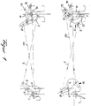
- the embodiment shown in the drawing is based on a motor vehicle door which is not shown in detail and which is attached by means of a joint parallelogram consisting of at least one support part and at least one control part to a vehicle body, which in turn is not shown in detail either, and which corresponds to this articulation characteristic in the course of both its opening and opening their closing movement carries out a swiveling movement superimposed by a transverse movement, a fixed locking pin 1 or 2 being arranged on each of the two door pillars delimiting a door opening in the vehicle body.
- a first rotary latch 3 and in the area of the rear end of the vehicle door a second rotary latch 4 are each pivotably articulated about a fixed axis 5 or 6 oriented transversely to the pivot axis of the vehicle door.
- the first rotary latch 3 is designed as a fork latch and at the same time forms the lock latch of the door lock, while the second rotary latch 4 is designed as a latch.
- the two rotary latches 3 and 4 are in a forced mutual drive connection via wire pulls 60 and 7, the lock latch 3 being the driving and the rotary latch 4 being the towed rotary latch.
- both rotary latches are also provided with an extension 8 forming a lever arm and engage the crosswise arranged wire pulls on the one hand on the lever arm 8 of the one and on the latch part 9 and 10 of the other rotary latches 3 and 4, such that the Rotary latch 4 with a pivoting movement of the lock latch forming catch 3 is forcibly adjusted synchronously and in the same direction.
- the fork latch 3 forming the lock latch has two unequally long fork tines 11 and 12, the first longer fork tine 11 already coming into contact with the associated locking bolt 1 when the vehicle door is in a position parallel to its closed position in front of the door opening of the vehicle body, and in this Position assumes the pre-locking position.
- the locking bolt 2 arranged on the other door pillar also engages with the latch area of the second rotary latch, the latch being designed in such a way that the locking pin only comes into contact with a part of the latch 4 which marks a latching area.
- the rotary latch 3 forming the lock latch then reaches a main latching or closed position and, due to its coupling with it, also tows the second rotary latch 4 into a locking position.
- the vehicle door is pulled against its sealing pressure into its locked, closed end position which is aligned with the vehicle body.
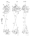
- the second rotary latch 4 is assigned a tension spring 13, which acts on the rotary latch 4 and, as a result of their coupling with it, also on the rotary latch 3 forming the lock latch in the direction of its release position.
- both the first rotary latch 3 forming the lock latch and the second rotary latch 4 are each assigned their own tension spring 13 or 14 acting in the direction of their release position.
- At least the rotary latch 3 forming the lock latch is assigned a stop 20 which limits its pivoting movement in the direction of the release position and which is fixedly arranged on the door body, this stop 20 interacting with the lever arm 8 connected to the rotary latch 3.
- the second rotary latch 4 is also assigned a stop 20, which limits its pivoting mobility in the direction of the release position, this stop 20 interacting with the latch part of the rotary latch 4.
- the position of the two rotary latches 3 and 4 is initially in the pre-locking or Catch position secured by a pawl 15 against reverse rotation, which is opposite the rotary latch 3, which forms the lock latch and is designed as a fork latch, and is rotatable in opposite directions on a fixed axis 16 and with the free end in rotary catches 3 and 4 located in the catch or pre-latched position of the longer fork tine 11 interacts positively.
- the pawl 15 When the vehicle door is moved into its closed position aligned with the vehicle body and the associated further pivoting movement of the lock latch 3, the pawl 15 then comes into positive engagement with the back surface 17 of the shorter second fork prong 12 of the fork latch 3 forming the lock latch and now secures the two rotary latches 3 and 4 in its main resting position.
- the pawl 15 can be coupled to a door handle or the like release handle 21 for the purpose of deliberately releasing the vehicle door, in particular for opening the same.
- the locking bolt la assigned to the lock latch 3 designed as a fork latch is adjustable in the vertical direction by means of a motor drive (not particularly shown in the drawing) along a vertical slot guide provided in the door pillar, such that, by means of a downward vertical adjustment of the locking bolt la, the lock latch 3 designed as a fork latch is moved from the catching or pre-latching position into the closing or main latching position.
- the second rotary latch 4 is also adjusted accordingly.
- the two rotary latches 3 and 4 are moved back into their catch or pre-locking position.
Landscapes
- Lock And Its Accessories (AREA)
Claims (17)
- Dispositif de fermeture pour portes de véhicules automobiles, qui sont montées dans la carrosserie du véhicule par l'intermédiaire d'un système articulé en forme de parallélogramme de façon à effectuer lors de leur ouverture ou fermeture simultanément un mouvement de pivotement et un mouvement transversal, et, qui sont équipées d'un dispositif de fermeture composé d'un étrier ou boulon de fermeture (1), (2) fixé de préférence sur la carrosserie et d'un pêne présentant une position d'arrêt préalable et une position de blocage principal et coopérant avec ledit étrier ou boulon de fermeture, caractérisé en ce que sur chacun des deux montants de porte délimitant l'ouverture dans la carrosserie est disposé un étrier ou boulon de fermeture (1), (2) fixe et sur chacun des bords frontaux de la porte est disposée une clenche oscillante (3), (4), la première clenche oscillante (3) étant constituée du pêne de la serrure de porte et couplée avec la deuxième clenche oscillante (4) de telle sorte que la clenche (3) est l'élément entraînant et la clenche (4) l'élément entraîné.
- Dispositif de fermeture selon la revendication 1 caractérisé en ce que au moins la clenche (3) entraînante est constituée d'une pièce en forme de fourche et la clenche (4) entraînée d'un cliquet.
- Dispositif de fermeture selon les revendications 1 et 2 caractérisé en ce que les deux clenches (3), (4) comportent chacune une zone d'engagement correspondant à une position de réception ou d'arrêt préalable, et, une zone d'engagement correspondant à la position de fermeture, respectivement de blocage de la porte.
- Dispositif de fermeture selon les revendications 1 à 3 caractérisé en ce que les dents (11), (12) délimitant l'ouverture de la fourche de la clenche entraînante (3) ne sont pas de même longueur, et, la partie de la dent la plus longue (11) saillante sur la dent la plus courte (12) marque la position de réception ou d'arrêt préalable.
- Dispositif de fermeture selon les revendications 1 à 4 caractérisé en ce que au moins la clenche (3) en forme de fourche coopère avec un cliquet (15) pouvant être dégagée en particulier manuellement, maintenant la clenche tant dans sa position de réception et d'arrêt préalable que dans sa position de fermeture en prévenant tout mouvement oscillant en arrière de la clenche.
- Dispositif de fermeture selon les revendications 1 à 5 caractérisé en ce que la clenche (3) en forme de fourche et le cliquet (15) sont disposés en étant articulés en sens opposé autour d'axes fixes se faisant face, le cliquet (15) coopérant avec l'extrémité de la clenche (3) en forme de fourche.
- Dispositif de fermeture selon les revendications 1 à 6 caractérisé en ce que le cliquet (15) est en position d'engagement avec l'extrémité libre de la dent (11) la plus longue de la clenche en forme de fourche lorsque ladite clenche se trouve en position de réception ou d'arrêt préalable, et, en position d'engagement avec la surface arrière (17) de la dent (12) la plus courte de ladite clenche lorsque cette dernière se trouve en position de fermeture ou de blocage principal.
- Dispositif de fermeture selon les revendications 1 à 7 caractérisé en ce que sur la surface arrière (17) de la dent la plus courte (12) de la clenche (3) est prévue une saillie d'arrêt (18) assurant le maintien de la position d'engagement du cliquet (15).
- Dispositif de fermeture selon l'une des revendications 1 à 8 caractérisé en ce que la clenche entraînée (4) est couplée en vue de son entraînement avec la clenche entraînante (3) par l'intermédiaire d'un élément de couplage (7), (60) transmettant au moins des forces de traction, tel une tige, une commande par fil ou une commande Bowden.
- Dispositif de fermeture selon l'une des revendications 1 à 9 caractérisé en ce que au moins la clenche entraînante (3) subit dans le sens du dégagement la force d'un ressort.
- Dispositif de fermeture selon l'une des revendications 1 à 9 caractérisé en ce que les deux clenches oscillantes, à savoir la clenche entraînante (3) et la clenche entraînée (4) subissent dans le sens du dégagement la force d'un ressort, en particulier d'une ressort de traction.
- Dispositif de fermeture selon l'une des revendications 1 à 11 caractérisé en ce que en liaison avec le ressort de charge (14) au moins l'une (3) des clenches oscillantes coopère avec une butée fixe (20) qui détermine la position d'ouverture extrême de la clenche.
- Dispositif de fermeture selon l'une des revendications 1 à 12 caractérisé en ce que les deux clenches oscillantes (3), (4) sont pourvues chacune d'un prolongement formant un bras de levier (8) et couplées entre elles en vue de leur entraînement par deux éléments de traction (7), (60), en particulier une commande Bowden ou une commande par fils, disposés en croix, dont chacun relie le bras de levier d'une des clenches à la partie principale de l'autre clenche.
- Dispositif de fermeture selon l'une des revendications 1 à 13 caractérisé en ce que les deux clenches oscillantes (3), (4) sont couplées en vue de leur entraînement par un seul élément (7), (60) transmettant une pression et des forces de traction.
- Dispositif de fermeture selon l'une des revendications 1 à 14 caractérisé en ce que le cliquet (15) est déplaçable par l'intermédiaire d'une poignée de porte actionnée manuellement.
- Dispositif de fermeture selon l'une des revendications 1 à 14 caractérisé en ce que la clenche oscillante (3) ou le cliquet (15) est déplaçable depuis sa position de réception ou d'arrêt préalable dans sa position de fermeture ou de blocage principal par l'intermédiaire d'un moteur, en particulier un moteur électrique.
- Dispositif de fermeture selon l'une des revendications 1 à 15 caractérisé en ce que le boulon ou l'étrier de fermeture (1), (2) est maintenu sur le montant de porte en étant déplaçable dans une glissière verticale et peut être déplacé par l'intermédiaire d'un moteur électrique depuis une position correspondant à la position de réception ou d'arrêt préalable de la clenche en forme de fourche dans une position correspondant à la position de fermeture ou de blocage principal de ladite clenche.
Applications Claiming Priority (2)
| Application Number | Priority Date | Filing Date | Title |
|---|---|---|---|
| DE4305738A DE4305738A1 (de) | 1993-02-25 | 1993-02-25 | Türschließeinrichtung für Kraftwagentüren |
| DE4305738 | 1993-02-25 |
Publications (2)
| Publication Number | Publication Date |
|---|---|
| EP0612901A1 EP0612901A1 (fr) | 1994-08-31 |
| EP0612901B1 true EP0612901B1 (fr) | 1996-02-14 |
Family
ID=6481263
Family Applications (1)
| Application Number | Title | Priority Date | Filing Date |
|---|---|---|---|
| EP94101327A Expired - Lifetime EP0612901B1 (fr) | 1993-02-25 | 1994-01-29 | Dispositif de fermeture pour portes de véhicules |
Country Status (3)
| Country | Link |
|---|---|
| EP (1) | EP0612901B1 (fr) |
| DE (2) | DE4305738A1 (fr) |
| ES (1) | ES2083300T3 (fr) |
Families Citing this family (6)
| Publication number | Priority date | Publication date | Assignee | Title |
|---|---|---|---|---|
| DE4325266A1 (de) * | 1993-07-28 | 1995-02-02 | Scharwaechter Gmbh Co Kg | Türschließeinrichtung für Kraftwagentüren |
| EP1330584B1 (fr) * | 2000-11-01 | 2014-06-11 | Southco, Inc. | Dispositif de verrouillage |
| DE102006033043B4 (de) * | 2006-07-14 | 2010-03-18 | Johnson Controls Interiors Gmbh & Co. Kg | Ver- und Entriegelungsmechanismus für den Deckel eines Handschuhfachs |
| DE202008012500U1 (de) * | 2008-09-19 | 2010-04-15 | Gebr. Bode Gmbh & Co. Kg | Türanordnung mit mechanischer Gesperrekopplung |
| US20170298657A1 (en) * | 2016-04-14 | 2017-10-19 | Ford Global Technologies, Llc | Dual cable door latch release mechanism |
| DE102016112260A1 (de) * | 2016-07-05 | 2018-01-11 | Kiekert Ag | Elektrisch betätigbares kraftfahrzeugschloss |
Family Cites Families (8)
| Publication number | Priority date | Publication date | Assignee | Title |
|---|---|---|---|---|
| US2896990A (en) * | 1956-01-06 | 1959-07-28 | Gen Motors Corp | Vehicle closure latch |
| US2943879A (en) * | 1957-05-10 | 1960-07-05 | Lisle W Menzimer | Latch mechanism |
| DE2263421A1 (de) * | 1972-12-27 | 1974-07-04 | Volkswagenwerk Ag | Schlossanordnung fuer eine schiebetuer, insbesondere eines kraftfahrzeuges |
| US4273368A (en) * | 1979-07-06 | 1981-06-16 | American Safety Equipment Corporaion | Dual latching mechanism for a flexible deck lid |
| IT8321700U1 (it) * | 1983-05-02 | 1984-11-02 | Alfa Romeo Spa | Serratura per il cofano di un vano di una vettura |
| US4662109A (en) * | 1984-12-28 | 1987-05-05 | Nissan Shatai Company, Limited | Sliding door lock arrangement |
| DE3642242A1 (de) * | 1986-12-10 | 1988-06-23 | Bayerische Motoren Werke Ag | Verriegelungseinrichtung fuer tueren, hauben, klappen o.dgl. von fahrzeugen, insbesondere kraftfahrzeugen |
| DE3718209A1 (de) * | 1987-05-29 | 1988-12-15 | Scharwaechter Gmbh Co Kg | Kraftwagen-tuerfeststeller |
-
1993
- 1993-02-25 DE DE4305738A patent/DE4305738A1/de not_active Withdrawn
-
1994
- 1994-01-29 ES ES94101327T patent/ES2083300T3/es not_active Expired - Lifetime
- 1994-01-29 EP EP94101327A patent/EP0612901B1/fr not_active Expired - Lifetime
- 1994-01-29 DE DE59400114T patent/DE59400114D1/de not_active Expired - Fee Related
Also Published As
| Publication number | Publication date |
|---|---|
| ES2083300T3 (es) | 1996-04-01 |
| DE59400114D1 (de) | 1996-03-28 |
| DE4305738A1 (de) | 1994-10-13 |
| EP0612901A1 (fr) | 1994-08-31 |
Similar Documents
| Publication | Publication Date | Title |
|---|---|---|
| EP2342405A1 (fr) | Verrou pour véhicule à moteur | |
| EP3899179B1 (fr) | Dispositif d'installation pour une porte de véhicule automobile | |
| EP3500714B1 (fr) | Ensemble logique de serrure | |
| DE19933371A1 (de) | Schließeinrichtung mit Zuziehhilfe | |
| EP1617031A2 (fr) | Porte coulissante pour un véhicule | |
| EP1801332A2 (fr) | Serrure pour véhicule automobile | |
| DD219985A5 (de) | Ausschwingtuer mit betaetigungseinrichtung | |
| EP1187963A1 (fr) | Dispositif de blocage et dispositif d'entrainement de porte pourvu d'un tel dispositif de blocage et destine a une porte entrainee par un groupe moteur | |
| EP0612901B1 (fr) | Dispositif de fermeture pour portes de véhicules | |
| DE102011108438A1 (de) | Kraftfahrzeugschloss | |
| DE19518493C2 (de) | Antriebseinrichtung für ein Torblatt | |
| DE19902150A1 (de) | Ausstellvorrichtung für einen an einem Rahmen schwenkbar angebrachten Kipp- oder Dreh-Kipp-Flügel | |
| DE10320439A1 (de) | Kraftfahrzeugtürverschluss | |
| DE9302707U1 (de) | Türschließeinrichtung für Kraftwagentüren | |
| DE10112120A1 (de) | Zuziehhilfsvorrichtung | |
| DE4228235A1 (de) | Verriegelungseinrichtung für Schlösser an Türen von Kraftfahrzeugen | |
| DE102019131684A1 (de) | Kraftfahrzeug-Türschlossanordnung für eine Schiebetür eines Kraftfahrzeugs | |
| EP1255905A1 (fr) | Dispositif d'actionnement | |
| EP0636759B1 (fr) | Dispositif de fermeture pour portes de véhicules | |
| EP0942123A1 (fr) | Dispositif pour verrouiller un couvercles notamment pour la capote d'un véhicule | |
| EP1288418B1 (fr) | Ferrure pour une fenêtre basculante ou oscillo-battante | |
| EP3744929B1 (fr) | Fermeture à crémone | |
| DE29813797U1 (de) | Türschloß mit einer Öffnungshilfe | |
| EP0197025A1 (fr) | Dispositif à actionner en cas de danger pour verrouillages de portes sans poignée | |
| EP3192952B1 (fr) | Serrure de véhicule automobile |
Legal Events
| Date | Code | Title | Description |
|---|---|---|---|
| PUAI | Public reference made under article 153(3) epc to a published international application that has entered the european phase |
Free format text: ORIGINAL CODE: 0009012 |
|
| 17P | Request for examination filed |
Effective date: 19940129 |
|
| AK | Designated contracting states |
Kind code of ref document: A1 Designated state(s): DE ES FR GB IT |
|
| 17Q | First examination report despatched |
Effective date: 19950804 |
|
| GRAA | (expected) grant |
Free format text: ORIGINAL CODE: 0009210 |
|
| AK | Designated contracting states |
Kind code of ref document: B1 Designated state(s): DE ES FR GB IT |
|
| ET | Fr: translation filed | ||
| GBT | Gb: translation of ep patent filed (gb section 77(6)(a)/1977) |
Effective date: 19960212 |
|
| REF | Corresponds to: |
Ref document number: 59400114 Country of ref document: DE Date of ref document: 19960328 |
|
| REG | Reference to a national code |
Ref country code: ES Ref legal event code: FG2A Ref document number: 2083300 Country of ref document: ES Kind code of ref document: T3 |
|
| ITF | It: translation for a ep patent filed | ||
| PLBE | No opposition filed within time limit |
Free format text: ORIGINAL CODE: 0009261 |
|
| STAA | Information on the status of an ep patent application or granted ep patent |
Free format text: STATUS: NO OPPOSITION FILED WITHIN TIME LIMIT |
|
| 26N | No opposition filed | ||
| PGFP | Annual fee paid to national office [announced via postgrant information from national office to epo] |
Ref country code: GB Payment date: 20011214 Year of fee payment: 9 |
|
| PGFP | Annual fee paid to national office [announced via postgrant information from national office to epo] |
Ref country code: FR Payment date: 20011226 Year of fee payment: 9 |
|
| REG | Reference to a national code |
Ref country code: GB Ref legal event code: IF02 |
|
| PGFP | Annual fee paid to national office [announced via postgrant information from national office to epo] |
Ref country code: ES Payment date: 20020118 Year of fee payment: 9 |
|
| PGFP | Annual fee paid to national office [announced via postgrant information from national office to epo] |
Ref country code: DE Payment date: 20030124 Year of fee payment: 10 |
|
| PG25 | Lapsed in a contracting state [announced via postgrant information from national office to epo] |
Ref country code: GB Free format text: LAPSE BECAUSE OF NON-PAYMENT OF DUE FEES Effective date: 20030129 |
|
| PG25 | Lapsed in a contracting state [announced via postgrant information from national office to epo] |
Ref country code: ES Free format text: LAPSE BECAUSE OF NON-PAYMENT OF DUE FEES Effective date: 20030130 |
|
| GBPC | Gb: european patent ceased through non-payment of renewal fee | ||
| PG25 | Lapsed in a contracting state [announced via postgrant information from national office to epo] |
Ref country code: FR Free format text: LAPSE BECAUSE OF NON-PAYMENT OF DUE FEES Effective date: 20030930 |
|
| REG | Reference to a national code |
Ref country code: FR Ref legal event code: ST |
|
| PG25 | Lapsed in a contracting state [announced via postgrant information from national office to epo] |
Ref country code: DE Free format text: LAPSE BECAUSE OF NON-PAYMENT OF DUE FEES Effective date: 20040803 |
|
| REG | Reference to a national code |
Ref country code: ES Ref legal event code: FD2A Effective date: 20030130 |
|
| PG25 | Lapsed in a contracting state [announced via postgrant information from national office to epo] |
Ref country code: IT Free format text: LAPSE BECAUSE OF NON-PAYMENT OF DUE FEES;WARNING: LAPSES OF ITALIAN PATENTS WITH EFFECTIVE DATE BEFORE 2007 MAY HAVE OCCURRED AT ANY TIME BEFORE 2007. THE CORRECT EFFECTIVE DATE MAY BE DIFFERENT FROM THE ONE RECORDED. Effective date: 20050129 |