EP0612575B1 - Bohrwerkzeug - Google Patents
Bohrwerkzeug Download PDFInfo
- Publication number
- EP0612575B1 EP0612575B1 EP93119663A EP93119663A EP0612575B1 EP 0612575 B1 EP0612575 B1 EP 0612575B1 EP 93119663 A EP93119663 A EP 93119663A EP 93119663 A EP93119663 A EP 93119663A EP 0612575 B1 EP0612575 B1 EP 0612575B1
- Authority
- EP
- European Patent Office
- Prior art keywords
- slots
- drilling tool
- tool according
- arms
- drill bit
- Prior art date
- Legal status (The legal status is an assumption and is not a legal conclusion. Google has not performed a legal analysis and makes no representation as to the accuracy of the status listed.)
- Expired - Lifetime
Links
Images
Classifications
-
- B—PERFORMING OPERATIONS; TRANSPORTING
- B28—WORKING CEMENT, CLAY, OR STONE
- B28D—WORKING STONE OR STONE-LIKE MATERIALS
- B28D1/00—Working stone or stone-like materials, e.g. brick, concrete or glass, not provided for elsewhere; Machines, devices, tools therefor
- B28D1/02—Working stone or stone-like materials, e.g. brick, concrete or glass, not provided for elsewhere; Machines, devices, tools therefor by sawing
- B28D1/04—Working stone or stone-like materials, e.g. brick, concrete or glass, not provided for elsewhere; Machines, devices, tools therefor by sawing with circular or cylindrical saw-blades or saw-discs
- B28D1/041—Working stone or stone-like materials, e.g. brick, concrete or glass, not provided for elsewhere; Machines, devices, tools therefor by sawing with circular or cylindrical saw-blades or saw-discs with cylinder saws, e.g. trepanning; saw cylinders, e.g. having their cutting rim equipped with abrasive particles
-
- B—PERFORMING OPERATIONS; TRANSPORTING
- B23—MACHINE TOOLS; METAL-WORKING NOT OTHERWISE PROVIDED FOR
- B23B—TURNING; BORING
- B23B51/00—Tools for drilling machines
- B23B51/04—Drills for trepanning
- B23B51/0426—Drills for trepanning with centering devices
Definitions
- the invention relates to a drilling tool, in particular for stone processing, according to the preamble of claim 1.
- a drilling tool in particular for stone processing, according to the preamble of claim 1.
- the removable center drill having a plurality of lateral bolts which with play in open-ended, paraxial slots in the Core bits can be used.
- This drilling tool has the disadvantage that the center drill can easily fall out. Before starting the tool, it must be held by hand, at least when drilling downwards.
- the drilling tool according to the invention with the characterizing feature of claim 1 has the advantage that the center drill is held self-locking in the drill bit with quick and easy assembly without auxiliary tools.
- the manufacturing effort is minimal and the center drill cannot fall out automatically even when the drill bit is held down because the arms wedge in the slanted slots.
- the drilling tool specified in claim 1 can be additionally improved by the further measures listed in the dependent claims. It is particularly advantageous to choose an angle of 20 ° to 30 °, preferably 25 °, for the slots. This enables easy assembly due to the short rotation required and on the other hand reliably prevents it from falling out automatically. If the width of the slots approximately corresponds to the diameter of the arms, in particular if there is a sliding fit, the minimum necessary slot length results.
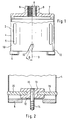
- Figure 1 shows a side view
- Figure 2 shows a cross section through the drilling tool according to the invention.
- the drilling tool according to the invention is designed as a drill bit 2 with a central axis 3 and a hollow cylindrical cutter holder 4.
- the cutter holder 4 has closed longitudinal slots 5 in the wall, which are used for cooling.
- Cutting segments 6 are placed on the front end face of the cutter carrier 4.
- Knife holder 4 and holder 7 can also consist of one piece.
- a threaded bore 8 and parallel key surfaces 9 are arranged for attaching a fork wrench.
- four edge-open slots 10 are cut into the cutter holder 4 in a rotationally symmetrical manner.
- the slots run at an angle ⁇ of 25 ° obliquely to the direction of the central axis 3 of the drill bit, namely in the direction of rotation backwards.
- a center drill bit 12 shown in FIG. 2 has a flat-cylindrical base body 13, into which a center drill 14 projecting toward the front is soldered in the center.
- Four arms 15 protrude radially to the side in a star shape. For example, they are firmly connected to the base body 13 with a press fit.
- the arms 15 are removably in the slots 10 of the cutter holder 4, so that the center drill 14 is held centrally in the drill bit 2. They protrude only slightly, for example 1 mm, from the cutter carrier 4, which allows drilling close to the edge and reduces the risk of injury.
- the width of the slots 10 corresponds to 6 mm to the diameter of the arms 15, so that there is a sliding fit.
- the length of the slots 10 corresponds to approximately twice their width. In any case, a length of the slots 10 corresponding to three times the width is sufficient to prevent the center drill bit 12 from falling out.
- the center drill bit 12 is inserted into the drill bit 2 by simply plugging it on and turning it slightly to the left. The hole to be made is then drilled until the cutting segments 5 have left a circular groove in the rock. Now the center drill bit 12 is removed again by turning it slightly to the right and the hole is drilled without a center drill.
- the center drill bit 12 cannot be released automatically.
- the center drill bit 12 tilts when the drill bit 2 is pivoted downwards.
- the arms 15 wedge in the slots 10.
- the one-sided tilting is additionally supported by differences in the coefficient of friction in the slots 10, which occur due to manufacturing tolerances or contamination.
- the angle ⁇ can also be chosen larger.
- the inclination of the slots 10 is of course chosen so that the center drill bit 12 is pressed into the slots 10 during drilling.
Landscapes
- Engineering & Computer Science (AREA)
- Mechanical Engineering (AREA)
- Mining & Mineral Resources (AREA)
- Processing Of Stones Or Stones Resemblance Materials (AREA)
- Drilling Tools (AREA)
- Cutting Tools, Boring Holders, And Turrets (AREA)
- Drilling And Boring (AREA)
Description
- Die Erfindung betrifft ein Bohrwerkzeug, insbesondere zur Steinbearbeitung, nach dem Oberbegriff des Anspruchs 1. Aus dem DE-GM 89 02 472 ist bereits ein solches Bohrwerkzeug bekannt, dessen herausnehmbarer Zentrierbohrer mehrere seitliche Bolzen aufweist, die mit Spiel in randoffene, achsparalelle Schlitze in der Bohrkrone einsetzbar sind. Dieses Bohrwerkzeug hat den Nachteil, daß der Zentrierbohrer leicht herausfallen kann. Vor dem Ansetzen des Werkzeugs muß er also mit der Hand gehalten werden, zumindest dann, wenn nach unten gebohrt werden soll.
- Um ein Herausfallen zu verhindern, wird in dem Dokument weiter vorgeschlagen, den Durchmesser der Langlöcher so zu wählen, daß sich die Bolzen unter leichter Reibung an den Langlöchern verschieben. Die Reibung bleibt aber in der praktischen Anwendung einerseits wegen des Verschleißes und andererseits wegen möglicher Verschmutzung der Bohrkrone nicht konstant, so daß ein zuverlässiger Schutz vor Herausfallen bei leichter Demontierbarkeit des Zentrierbohrers nicht gegeben ist. Das bedeutet, daß das Bohrwerkzeug bei schweren Bohrgeräten, die mit zwei Händen gehalten werden müssen, gar nicht oder zumindest nicht ohne Gefahr verwendbar ist.
- Bei einem auf dem Markt angebotenen Bohrwerkzeug sind gegen das Herausfallen des Zentrierbohrers radial abstehende, flexible Kunststofflappen angebracht, die sich gegen die Innenwand der Bohrkrone anpressen. Neben dem zusätzlichen Aufwand hat diese Lösung den Nachteil, daß zum bequemen Herausziehen des Zentrierbohrers gegen den Widerstand der Kunststofflappen die seitlichen Bolzen relativ weit aus der Bohrkrone herausstehen müssen.
- Das erfindungsgemäße Bohrwerkzeug mit dem kennzeichnenden Merkmal des Anspruchs 1 hat demgegenüber den Vorteil, daß der Zentrierbohrer bei schneller und kinderleichter Montierbarkeit ohne Hilfswerkzeug selbsthemmend in der Bohrkrone gehalten ist. Der Fertigungsaufwand ist minimal und der Zentrierbohrer kann auch bei nach unten gehaltener Bohrkrone nicht selbstätig herausfallen, da sich die Arme in den schrägstehenden Schlitzen verkeilen.
- Durch die weiteren in den abhängigen Ansprüchen aufgeführten Maßnahmen läßt sich das in Anspruch 1 angegebene Bohrwerkzeug zusätzlich verbessern. Besonders vorteilhaft ist es, für die Schlitze einen Winkel von 20° bis 30°, vorzugsweise 25° zu wählen. Dies ermöglicht wegen der nur kurzen notwendigen Drehung noch eine problemlose Montage und verhindert andererseits bereits zuverlässig ein selbstätiges Herausfallen. Wenn die Breite der Schlitze etwa dem Durchmesser der Arme entspricht, insbesondere wenn ein Schiebesitz vorliegt, ergibt sich eine minimale notwendige Schlitzlänge.
- Ein Ausführungsbeispiel der Erfindung ist in der Zeichnung dargestellt und in der nachfolgenden Beschreibung näher erläutert. Figur 1 zeigt eine Seitenansicht und Figur 2 einen Querschnitt durch das erfindungsgemäße Bohrwerkzeug.
- Das erfindungsgemäße Bohrwerkzeug ist als Bohrkrone 2 mit Mittelachse 3 und einem hohlzylindrischen Schneidenträger 4 ausgebildet. Der Schneidenträger 4 weist geschlossene Längsschlitze 5 in der Wandung auf, die der Kühlung dienen. An der vorderen Stirnfläche des Schneidenträgers 4 sind Schneidsegmente 6 aufgesetzt. Hinten ist der Schneidenträger 4 auf einem Halter 7 zum Aufschrauben auf die Spindel einer Bohr- oder Schlagbohrmaschine befestigt. Schneidenträger 4 und Halter 7 können auch aus einem Stück bestehen. An dem Halter 7 sind rückseitig eine Gewindebohrung 8 und parallele Schlüsselflächen 9 zum Ansetzen eines Gabelschlüssels angeordnet. In den Schneidenträger 4 sind von der vorderen Stirnfläche ausgehend rotationssymmetrisch verteilt vier randoffene Schlitze 10 eingeschnitten. Die Schlitze verlaufen unter einem Winkel β von 25° schräg zur Richtung der Mittelachse 3 der Bohrkrone, und zwar in Drehrichtung rückwärts.
- Ein in Figur 2 gezeigter Zentrierbohrereinsatz 12 weist einen flachzylindrischen Grundkörper 13 auf, in den zentrisch ein nach vorne herausstehender Zentrierbohrer 14 eingelötet ist. Radial seitlich stehen vier Arme 15 sternförmig heraus. Sie sind z.B. mit Preßpassung fest mit dem Grundkörper 13 verbunden. Die Arme 15 liegen herausnehmbar in den Schlitzen 10 des Schneidenträgers 4, so daß der Zentrierbohrer 14 zentrisch in der Bohrkrone 2 gehalten ist. Sie Überragen den Schneidenträger 4 nur geringfügig, z.B. 1 mm, was randnahes Bohren erlaubt und die Verletzungsgefahr mindert. Die Breite der Schlitze 10 entspricht mit 6 mm dem Durchmesser der Arme 15, so daß sich ein Schiebesitz ergibt. Die Länge der Schlitze 10 entspricht etwa ihrer doppelten Breite. Jedenfalls reicht eine der dreifachen Breite entsprechende Länge der Schlitze 10 aus, um ein Herausfallen des Zentrierbohrereinsatzes 12 zu verhindern.
- Vor dem Ansetzen der Bohrkrone an das zu bearbeitende Gestein wird der Zentrierbohrereinsatz 12 durch einfaches Aufstecken und leichtes Linksdrehen in die Bohrkrone 2 eingesetzt. Sodann wird das anzubringende Loch solange angebohrt, bis die Schneidsegmente 5 eine kreisförmige Rinne im Gestein hinterlassen haben. Nun wird der Zentrierbohrereinsatz 12 unter leichtem Rechtsdrehen wieder herausgenommen und das Loch ohne Zentrierbohrer fertiggebohrt.
- Wegen der notwendigen Drehbewegung um die Mittelachse 3 kann sich der Zentrierbohrereinsatz 12 nicht selbstätig lösen. Insbesondere deshalb, weil der Zentrierbohrereinsatz 12 kippt, wenn die Bohrkrone 2 nach unten geschwenkt wird. Dabei verkeilen sich die Arme 15 in den Schlitzen 10. Das einseitige Kippen wird zusätzlich durch Reibwertdifferenzen in den Schlitzen 10 unterstützt, die aufgrund von Fertigungstoleranzen oder Verschmutzung auftreten. Bei stark verschleißgefährdeten Bohrwerkzeugen kann der Winkel β auch größer gewählt werden. Die Neigung der Schlitze 10 wird selbstverständlich so gewählt, daß der Zentrierbohrereinsatz 12 beim Bohren in die Schlitze 10 hineingedrängt wird.
Claims (7)
- Bohrwerkzeug, insbesondere zur Steinbearbeitung, mit einer hohlzylindrischen Bohrkrone (2) und einem mittig in dieser gehaltenen Zentrierbohrereinsatz (12), welcher seitlich sternförmig herausragend mindestens drei Arme (15) aufweist, die in randoffene Schlitze (10) der Bohrkrone (2) einsetzbar sind, dadurch gekennzeichnet, daß die Schlitze (10) schräg zur Richtung der Mittelachse (3) der Bohrkrone (2) angeordnet sind.
- Bohrwerkzeug nach Anspruch 1, dadurch gekennzeichnet, daß die Schlitze (10) in einem Winkel von ca. 20 - 30° schräg zur Richtung der Mittelachse (3) verlaufen.
- Bohrwerkzeug nach Anspruch 1 oder 2, dadurch gekennzeichnet, daß die Breite der Schlitze (10) dem Durchmesser der Arme (15) entspricht.
- Bohrwerkzeug nach einem der vorhergehenden Ansprüche, dadurch gekennzeichnet, daß die Arme (15) mit Schiebesitz in den Schlitzen (10) aufgenommen sind.
- Bohrwerkzeug nach einem der vorhergehenden Ansprüche, dadurch gekennzeichnet, daß die Schlitze (10) etwa doppelt so lang wie breit sind.
- Bohrwerkzeug nach einem der vorhergehenden Ansprüche, dadurch gekennzeichnet, daß die Arme (15) den Schneidenträger (4) nur geringfügig überragen.
- Bohrwerkzeug nach einem der vorhergehenden Ansprüche, dadurch gekennzeichnet, daß der Schneidenträger (4) Längsschlitze (5) zur Kühlung der Bohrkrone (2) aufweist.
Applications Claiming Priority (2)
| Application Number | Priority Date | Filing Date | Title |
|---|---|---|---|
| DE9302487U DE9302487U1 (de) | 1993-02-20 | 1993-02-20 | Bohrwerkzeug |
| DE9302487U | 1993-02-20 |
Publications (2)
| Publication Number | Publication Date |
|---|---|
| EP0612575A1 EP0612575A1 (de) | 1994-08-31 |
| EP0612575B1 true EP0612575B1 (de) | 1997-03-19 |
Family
ID=6889664
Family Applications (1)
| Application Number | Title | Priority Date | Filing Date |
|---|---|---|---|
| EP93119663A Expired - Lifetime EP0612575B1 (de) | 1993-02-20 | 1993-12-07 | Bohrwerkzeug |
Country Status (3)
| Country | Link |
|---|---|
| EP (1) | EP0612575B1 (de) |
| JP (1) | JP3001185U (de) |
| DE (2) | DE9302487U1 (de) |
Cited By (3)
| Publication number | Priority date | Publication date | Assignee | Title |
|---|---|---|---|---|
| DE19717031C1 (de) * | 1997-04-23 | 1998-10-01 | Duss Maschf | Bohrmaschine zur Erzeugung von Ausnehmungen in Wänden |
| US9579732B2 (en) | 2012-07-18 | 2017-02-28 | Milwaukee Electric Tool Corporation | Hole saw |
| US11845134B2 (en) | 2018-07-10 | 2023-12-19 | Milwaukee Electric Tool Corporation | Hole saw with hex sidewall holes |
Families Citing this family (17)
| Publication number | Priority date | Publication date | Assignee | Title |
|---|---|---|---|---|
| DE4420999C2 (de) | 1994-06-17 | 2003-10-09 | Hilti Ag | Hohlbohrwerkzeug mit auswechselbarem Zentrierbohrer |
| DE4441275B4 (de) * | 1994-11-19 | 2004-03-25 | Robert Bosch Gmbh | Zentrierbohreinsatz für ein Hohlbohrwerkzeug |
| GB9520965D0 (en) * | 1995-10-13 | 1995-12-13 | Gilbert David | Computer furniture |
| EP0799967B1 (de) * | 1996-04-01 | 2001-10-24 | Hawera Probst GmbH | Bohrkrone mit Zentrierbohrer |
| DE19629837A1 (de) * | 1996-04-01 | 1997-10-02 | Hawera Probst Gmbh | Bohrkrone mit Zentrierbohrer |
| DE10064679A1 (de) * | 2000-12-22 | 2002-07-04 | Fischer Artur Werke Gmbh | Abstandshalter für die Befestigung eines Bauteils an einer eine Dämmschicht aufweisenden Wand oder dgl., sowie Verfahren und Werkzeug zum Setzen des Abstandshalters |
| WO2009015488A1 (en) * | 2007-08-01 | 2009-02-05 | Satnam Singh | Hole saw system with improved slug removability |
| DE102011081415A1 (de) * | 2011-08-23 | 2013-02-28 | Robert Bosch Gmbh | Sägeblatt |
| CN102390093A (zh) * | 2011-09-27 | 2012-03-28 | 泉州市洛江区双阳金刚石工具有限公司 | 一种金刚石钻头 |
| US10532412B2 (en) | 2016-09-23 | 2020-01-14 | Milwaukee Electric Tool Corporation | Hole saw arbor assembly |
| EP3725441B1 (de) | 2017-01-06 | 2025-04-09 | Milwaukee Electric Tool Corporation | Lochsäge |
| USD973733S1 (en) | 2017-08-15 | 2022-12-27 | Milwaukee Electric Tool Corporation | Hole saw |
| AU2020295404B2 (en) | 2019-06-20 | 2025-05-29 | Milwaukee Electric Tool Corporation | Hole saw with circular sidewall openings |
| USD958855S1 (en) | 2019-12-09 | 2022-07-26 | Milwaukee Electric Tool Corporation | Hole saw |
| CN113211656B (zh) * | 2021-04-30 | 2023-05-16 | 漳州市闽华建筑工程有限公司 | 一种墙面自动开槽机 |
| JP7814019B2 (ja) * | 2021-07-27 | 2026-02-16 | 株式会社大林組 | 穿孔方法及び穿孔装置 |
| FR3149638B1 (fr) * | 2023-06-12 | 2025-10-17 | Diager | Trepan adapté a la percussion |
Family Cites Families (4)
| Publication number | Priority date | Publication date | Assignee | Title |
|---|---|---|---|---|
| US3524663A (en) * | 1969-05-16 | 1970-08-18 | Mueller Co | Releasable drive coupling |
| DE3107648C1 (de) * | 1981-02-27 | 1982-12-16 | Eisengießerei und Maschinenfabrik Keulahütte GmbH, 2120 Lüneburg | Ventilanborarmatur |
| DE8513328U1 (de) * | 1985-05-07 | 1985-10-31 | Geißler & Kuper GmbH Diamantwerkzeug - Wiederaufbereitung, 3100 Celle | Diamantbohrkrone mit Schaftrohr und Rohrgewindeanschluß |
| DE8902472U1 (de) * | 1989-03-02 | 1989-04-06 | BSB Biedron GmbH, 4630 Bochum | Hohlbohrer |
-
1993
- 1993-02-20 DE DE9302487U patent/DE9302487U1/de not_active Expired - Lifetime
- 1993-12-07 EP EP93119663A patent/EP0612575B1/de not_active Expired - Lifetime
- 1993-12-07 DE DE59305875T patent/DE59305875D1/de not_active Expired - Fee Related
-
1994
- 1994-02-18 JP JP1994000758U patent/JP3001185U/ja not_active Expired - Lifetime
Cited By (3)
| Publication number | Priority date | Publication date | Assignee | Title |
|---|---|---|---|---|
| DE19717031C1 (de) * | 1997-04-23 | 1998-10-01 | Duss Maschf | Bohrmaschine zur Erzeugung von Ausnehmungen in Wänden |
| US9579732B2 (en) | 2012-07-18 | 2017-02-28 | Milwaukee Electric Tool Corporation | Hole saw |
| US11845134B2 (en) | 2018-07-10 | 2023-12-19 | Milwaukee Electric Tool Corporation | Hole saw with hex sidewall holes |
Also Published As
| Publication number | Publication date |
|---|---|
| JP3001185U (ja) | 1994-08-23 |
| DE9302487U1 (de) | 1994-06-23 |
| EP0612575A1 (de) | 1994-08-31 |
| DE59305875D1 (de) | 1997-04-24 |
Similar Documents
| Publication | Publication Date | Title |
|---|---|---|
| EP0612575A1 (de) | Bohrwerkzeug | |
| EP0687516B1 (de) | Kombinationswerkzeug | |
| CH678834A5 (de) | ||
| DE4032176C2 (de) | Scheibenschneider | |
| DE2624370B2 (de) | Scheibenschneider für Blech o.dgl | |
| EP1009595A2 (de) | Mit der antriebswelle einer drehmaschine kuppelbares werkzeugsystem | |
| DE29914047U1 (de) | Schneidkopf zum selbstklemmenden Befestigen auf einem Werkzeughalter | |
| EP0054774A2 (de) | Spannfutter | |
| DE10028016B4 (de) | Verriegelungs-Spannfutter und Antrieb mit einem solchen Spannfutter | |
| EP1447195B1 (de) | Bohrvorrichtung mit einem Hohlbohrer | |
| DE2508316A1 (de) | Muffen-haltevorrichtung fuer ein rotierendes, kraftbetriebenes werkzeug | |
| DE4239559C2 (de) | Handwerkzeugmaschine mit einer Blockiereinrichtung zum Blockieren der Werkzeugspindel beim Werkzeugwechsel | |
| DE3004077C2 (de) | Bohrkrone | |
| DE10333061B4 (de) | Bohrkopf | |
| DE102013104874B3 (de) | Werkzeugrevolver | |
| DE2159405A1 (de) | Spannfutter | |
| DE69725185T2 (de) | Handbetätigtes futter | |
| EP0693013B1 (de) | Modulares werkzeugsystem | |
| WO2008052623A1 (de) | Werkzeughalter | |
| EP1356883A1 (de) | Kernbohrvorrichtung | |
| DE1502083A1 (de) | Verbesserungen an Fraesern | |
| DE202015103583U1 (de) | Werkzeughalter zur lösbaren Befestigung wenigstens eines Schneideinsatzes | |
| DE2328176B2 (de) | Mehrteiliger Schaftfräser | |
| CH664104A5 (de) | Bohrfutter. | |
| DE8335453U1 (de) | Zentrierbohrer für eine Hohlbohrkrone |
Legal Events
| Date | Code | Title | Description |
|---|---|---|---|
| PUAI | Public reference made under article 153(3) epc to a published international application that has entered the european phase |
Free format text: ORIGINAL CODE: 0009012 |
|
| AK | Designated contracting states |
Kind code of ref document: A1 Designated state(s): CH DE GB IT LI SE |
|
| 17P | Request for examination filed |
Effective date: 19950228 |
|
| 17Q | First examination report despatched |
Effective date: 19950803 |
|
| GRAG | Despatch of communication of intention to grant |
Free format text: ORIGINAL CODE: EPIDOS AGRA |
|
| GRAH | Despatch of communication of intention to grant a patent |
Free format text: ORIGINAL CODE: EPIDOS IGRA |
|
| GRAH | Despatch of communication of intention to grant a patent |
Free format text: ORIGINAL CODE: EPIDOS IGRA |
|
| GRAA | (expected) grant |
Free format text: ORIGINAL CODE: 0009210 |
|
| AK | Designated contracting states |
Kind code of ref document: B1 Designated state(s): CH DE GB IT LI SE |
|
| REG | Reference to a national code |
Ref country code: CH Ref legal event code: NV Representative=s name: SCINTILLA AG, DIREKTION Ref country code: CH Ref legal event code: EP |
|
| REF | Corresponds to: |
Ref document number: 59305875 Country of ref document: DE Date of ref document: 19970424 |
|
| ITF | It: translation for a ep patent filed | ||
| GBT | Gb: translation of ep patent filed (gb section 77(6)(a)/1977) |
Effective date: 19970522 |
|
| PLBE | No opposition filed within time limit |
Free format text: ORIGINAL CODE: 0009261 |
|
| STAA | Information on the status of an ep patent application or granted ep patent |
Free format text: STATUS: NO OPPOSITION FILED WITHIN TIME LIMIT |
|
| 26N | No opposition filed | ||
| PGFP | Annual fee paid to national office [announced via postgrant information from national office to epo] |
Ref country code: GB Payment date: 19991129 Year of fee payment: 7 |
|
| PGFP | Annual fee paid to national office [announced via postgrant information from national office to epo] |
Ref country code: SE Payment date: 19991222 Year of fee payment: 7 |
|
| PGFP | Annual fee paid to national office [announced via postgrant information from national office to epo] |
Ref country code: CH Payment date: 19991223 Year of fee payment: 7 |
|
| PGFP | Annual fee paid to national office [announced via postgrant information from national office to epo] |
Ref country code: DE Payment date: 19991229 Year of fee payment: 7 |
|
| PG25 | Lapsed in a contracting state [announced via postgrant information from national office to epo] |
Ref country code: GB Free format text: LAPSE BECAUSE OF NON-PAYMENT OF DUE FEES Effective date: 20001207 |
|
| PG25 | Lapsed in a contracting state [announced via postgrant information from national office to epo] |
Ref country code: SE Free format text: LAPSE BECAUSE OF NON-PAYMENT OF DUE FEES Effective date: 20001208 |
|
| PG25 | Lapsed in a contracting state [announced via postgrant information from national office to epo] |
Ref country code: LI Free format text: LAPSE BECAUSE OF NON-PAYMENT OF DUE FEES Effective date: 20001231 Ref country code: CH Free format text: LAPSE BECAUSE OF NON-PAYMENT OF DUE FEES Effective date: 20001231 |
|
| GBPC | Gb: european patent ceased through non-payment of renewal fee |
Effective date: 20001207 |
|
| EUG | Se: european patent has lapsed |
Ref document number: 93119663.8 |
|
| REG | Reference to a national code |
Ref country code: CH Ref legal event code: PL |
|
| PG25 | Lapsed in a contracting state [announced via postgrant information from national office to epo] |
Ref country code: DE Free format text: LAPSE BECAUSE OF NON-PAYMENT OF DUE FEES Effective date: 20011002 |
|
| PG25 | Lapsed in a contracting state [announced via postgrant information from national office to epo] |
Ref country code: IT Free format text: LAPSE BECAUSE OF NON-PAYMENT OF DUE FEES;WARNING: LAPSES OF ITALIAN PATENTS WITH EFFECTIVE DATE BEFORE 2007 MAY HAVE OCCURRED AT ANY TIME BEFORE 2007. THE CORRECT EFFECTIVE DATE MAY BE DIFFERENT FROM THE ONE RECORDED. Effective date: 20051207 |