EP0610096B1 - Dispositif d'enregistrement par jet d'encre - Google Patents
Dispositif d'enregistrement par jet d'encre Download PDFInfo
- Publication number
- EP0610096B1 EP0610096B1 EP94300851A EP94300851A EP0610096B1 EP 0610096 B1 EP0610096 B1 EP 0610096B1 EP 94300851 A EP94300851 A EP 94300851A EP 94300851 A EP94300851 A EP 94300851A EP 0610096 B1 EP0610096 B1 EP 0610096B1
- Authority
- EP
- European Patent Office
- Prior art keywords
- ink
- recording
- discharge
- image
- discharge port
- Prior art date
- Legal status (The legal status is an assumption and is not a legal conclusion. Google has not performed a legal analysis and makes no representation as to the accuracy of the status listed.)
- Expired - Lifetime
Links
Images


Classifications
-
- B—PERFORMING OPERATIONS; TRANSPORTING
- B41—PRINTING; LINING MACHINES; TYPEWRITERS; STAMPS
- B41J—TYPEWRITERS; SELECTIVE PRINTING MECHANISMS, i.e. MECHANISMS PRINTING OTHERWISE THAN FROM A FORME; CORRECTION OF TYPOGRAPHICAL ERRORS
- B41J2/00—Typewriters or selective printing mechanisms characterised by the printing or marking process for which they are designed
- B41J2/005—Typewriters or selective printing mechanisms characterised by the printing or marking process for which they are designed characterised by bringing liquid or particles selectively into contact with a printing material
- B41J2/01—Ink jet
- B41J2/21—Ink jet for multi-colour printing
- B41J2/2121—Ink jet for multi-colour printing characterised by dot size, e.g. combinations of printed dots of different diameter
- B41J2/2125—Ink jet for multi-colour printing characterised by dot size, e.g. combinations of printed dots of different diameter by means of nozzle diameter selection
-
- B—PERFORMING OPERATIONS; TRANSPORTING
- B41—PRINTING; LINING MACHINES; TYPEWRITERS; STAMPS
- B41J—TYPEWRITERS; SELECTIVE PRINTING MECHANISMS, i.e. MECHANISMS PRINTING OTHERWISE THAN FROM A FORME; CORRECTION OF TYPOGRAPHICAL ERRORS
- B41J2/00—Typewriters or selective printing mechanisms characterised by the printing or marking process for which they are designed
- B41J2/005—Typewriters or selective printing mechanisms characterised by the printing or marking process for which they are designed characterised by bringing liquid or particles selectively into contact with a printing material
- B41J2/01—Ink jet
- B41J2/205—Ink jet for printing a discrete number of tones
- B41J2/2056—Ink jet for printing a discrete number of tones by ink density change
Definitions
- the present invention relates to an ink jet recording head and the recording by an ink jet recording apparatus. More particularly, the invention relates to the ink jet recording head which uses ink having different densities for the same color series for recording images.
- an apparatus which digitally records images by use of a recording head of an ink jet method has rapidly become popular as one of the image formation apparatuses (hereinafter referred to as recording apparatus) serving as information output means for these equipment.
- recording apparatus an apparatus which digitally records images by use of a recording head of an ink jet method
- recording apparatus serving as information output means for these equipment.
- the so-called multinozzle head in which a plurality of ink discharge ports, liquid passages conductively connected to these ports, and others are integrated, is used as a recording element in order to improve the recording speed.
- a recording method of the kind there is adopted for controlling a recording in an intermediate tone, a dot density control method with which to produce such an intermediate tone by controlling the number of recording dots per unit area by the application of the recording dots of a specific size, or a dot diameter control method with which to produce such an intermediate tone by controlling the sizes of the recording dots.
- the latter method which controls the dot diameters requires a complicated control to be carried out for the fine modification of the sizes of the recording dots, hence automatically restrict its implementation. In general, therefore, the former method which controls the dot densities is adopted.
- the electro-thermal energy transducing elements which make a high resolution possible, are used because of the ease with which to prepare the elements in a high density, but it is also difficult to control the amount of pressure variation, thus disabling the diameters of the recording dots to be modulated. For recording, therefore, the method for controlling dot density is adopted.
- an organizational design method may be employed. This method, however, has a problem that the number of gradations is limited by the matrix size. In other words, to increase the number of gradations, it is necessary to make the matrix size larger. If the matrix size is made larger, there is a problem encountered, among others, that one pixel of a recorded image consisting of one matrix becomes greater, thus spoiling the resolution. Also, there is a design method of a conditionally determining type, such as an error diffusion method as another typical type of binarization method.
- the aforesaid organizational design method is of an independently determining type for binarization using a threshold value which is not related to any input pixels
- this type of method varies the threshold value in consideration of the surrounding pixels of an inputted pixel.
- the design method of a conditionally determining type which is represented by the error diffusion method has an excellent compatibility of tonality and resolution.
- the creation of the moire pattern on the recording image is extremely small among other advantages, but, on the other hand, the graininess of the bright part of the image tends to become conspicuous, and a problem is encountered that the evaluation of the image quality is lowered. This problem is particularly conspicuous in a recording apparatus having a low recording density.
- the two recording heads which discharge ink having a low density of a recorded image, and ink having a high density thereof, respectively, are provided so that the recording dots are formed with ink having a low density (light ink) for the bright part to the intermediate tonal part of an image, and also formed with ink having a high density (dark ink) for the intermediate tonal part to the dark part of the image.
- Fig. 1 is a perspective view showing the principal part of a conventional color ink jet recording apparatus of a serial printing type which uses dark and light ink according to the above-mentioned recording method.
- a conventional color ink jet recording apparatus of a serial printing type which uses dark and light ink according to the above-mentioned recording method.
- Such an apparatus is disclosed in US-A-4635078.
- a recording head Kk which discharges black dark ink
- a recording head Ku black light ink
- a recording head Ck which discharges cyan dark ink
- a recording head Cu cyan light ink
- a recording head Mk which discharges magenta dark ink
- a recording head Mu magenta light ink
- a recording head Yk which discharges dark yellow ink
- a recording head Yu yellow light ink.
- the carriage 241 is slidably supported by a guide shaft 243 to be guided to reciprocate along the above-mentioned guide shaft 243 by the driving force of a carriage motor 245 transmitted through a driving belt 244.
- the heat generating elements are arranged to generate the thermal energy used for discharging ink.
- the ink used by each of the recording heads is retained in each of the ink cartridges 248 provided for the respective colors, and is supplied through each of the ink supply passages. Also, the control signals and driving signals are transmitted from an apparatus controller to the recording heads through a flexible cable 249.
- a recording material such as a recording sheet or a plastic thin sheet is conveyed in the direction indicated by arrows in Fig. 1 by means of a feed roller (not shown) and exhaust sheet rollers 242 when a feed motor (not shown) is driven. During this period, a recording is being executed on the surface of the recording material facing the recording heads along the traveling of each of the heads.
- the above-mentioned heat generating elements are driven on the basis of the recording signals to discharge each of the ink, black dark and light, cyan dark and light, magenta dark and light, and yellow dark and light, on the recording material in that order, thus enabling them to adhere thereto for recording images on the material.
- a recovery unit 246 is arranged with a capping unit 247. With the recovery process by this recovery unit, the ink discharge characteristics are stabilized for each of the recording heads.
- the conventional ink jet recording apparatus which uses the dark and light ink as described with reference to Fig. 1 can solve the problem of the graininess of the recorded image comparatively well, and presents one of effective techniques in improving the quality of recorded image.
- the conventional ink jet recording apparatus which uses the dark and light ink is at first provided with a recording head and an ink cartridge per ink to be used. Consequently, the number of recording heads and ink cartridges is increased, inevitably bringing about a larger size of the apparatus.
- the weight of the recording heads and the carriage is increased.
- the distance required for the ramp up and down becomes long when the carriage travels, thus resulting likewise in the larger size of the apparatus.
- the load required to drive the carriage is increased, necessitating the provision of a driving motor having a greater torque.
- a color printer for example, it is necessary for recording images to take into account various conditions, such as coloring ability, tonality, uniformity unlike a character printer and others which record only characters. Particularly, as to the uniformity, just a slight variation per nozzle created in the process of fabricating a multinozzle head produces adverse effects on the amount of discharged ink and the direction of discharges per discharge port in recording, resulting in the density unevenness in a recorded image to cause its quality to be degraded.
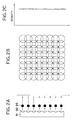
- a reference numeral 91 designates the so-called multinozzle head.
- the head is assumed to be structured with eight discharge ports 92 to discharge only one kind of ink having a single color and a single density.
- a reference numeral 93 designates ink droplets discharged from each of the discharge ports 92. As shown in Fig. 2A, it is ideal that the ink droplets 93 are discharged in the same amount and direction. Then, if the discharges are executed like this, the dots of the same size are recorded on a recording sheet as shown in Fig. 2B, thus making it possible to obtain an over all image uniformly without any density unevenness (see Fig. 2C).
- the lower four discharge ports are used to record the dots of four pixel arrays, respectively, and then, after feeding the sheet for a portion of four discharge ports, the dots are recorded by the second scan by use of the upper four discharge ports on the portion where no dots of the above-mentioned four pixel arrays are recorded.
- the dots which should be recorded by the second scan are thinned by approximately a half.
- the dots to be recorded by each scan are in a complementary relationship.
- a recording method such as this is called "divided recording method”.
- a recorded image is as shown in Fig. 4B because even when using a recording head whose discharge characteristics vary per discharge port as shown in Figs. 3A to 3C, its unfavorable effect to the recorded image per discharge port is reduced by half, hence making the black streak and white streak as shown in Fig. 3B less conspicuous. Therefore, compared to the density unevenness shown in Fig. 3C, there is also a considerably improvement in it as shown in Fig. 4C. Also, the joint streaks appearing at the boundaries between each of the scanning areas can be reduced by half if the divided recording method is applied because the dots on one pixel array are recorded by the discharge ports on the end portion of the recording head and those on the central portion of it.
- the image data are divided so that the dots are offset with each other (complementally) in accordance with certain arrays in the first and second scans.
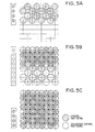
- this division of the image data (hereinafter, may also be referred to as "thinned patterns”) is most often such as shown in Figs. 5A to 5C so that the dots can be arranged in a cross pattern per pixel vertically and horizontally. Therefore, in a unit recording area (here, a unit of four pixels), a recording is completed by the first scan which records the cross pattern and the second scan which records the counter-cross pattern.
- Figs. 5A, 5B, and 5C are views illustrating the process in which a recording in a specific area is completed by use of the cross and counter-cross patterns, respectively.
- the dots 51 are recorded to form the cross pattern by use of the lower four nozzles (Fig. 5A).
- the dots 52 are recorded to from the counter-cross pattern (Fig. 5B) after the sheet is fed for a portion of four pixels (a 1/2 of the head length).
- the dots 53 are recording to from the cross pattern again (Fig. 5C) after the sheet is again fed for a portion of four pixels (a 1/2 of the head length).
- the sheet is fed for a four-pixel unit, and the cross and counter-cross patterns are recorded alternately, thus completing the recording area of the four-pixel unit per scan.
- the cross and counter-cross patterns are recorded alternately, thus completing the recording area of the four-pixel unit per scan.
- a recording method of the kind is disclosed in Japanese Patent Laid-Open Application No. 60-107975 and USP No. 4,967,203, for example, and it is described in these patent specifications, respectively, that the method is effectively applicable to solving the problem of the density unevenness and joint streaks.
- the method has means to form a superposed portion by making the sheet feed per each of the main scans smaller than the width of a main scan so that the two adjacent main scans are superposed, and means to arrange the two main scans so as not to allow the printed dots in the aforesaid superposed portion to be superposed.
- a thinning mask is defined as "printed in cross wise in an odd number stage and an even number stage per one array" in some cases, but in some other cases, the odd number stage is printed by a first main scan, and the even number stage is printed by a second scan or the recording is executed at random per scan. Hence there are no complete limits set to the thinning mask and the width of the sheet feed.
- the thinning mask which executes divided recordings is limited to the alternate pixel arrangement which is not adjacent in the vertical and horizontal directions such as disclosed to the effect that:
- a recording method is disclosed as an additional arrangement that several pixels are formed together as a super pixel to make a tonal representation and a multicolor representation, and that the alternate thinning printing is executed per super pixel. It is then described to the effect that according to this method, once a system to materialize the above-mentioned method is incorporated either in a programmed software or a printer firmware, such a program can be called by the color number of the combination designated for the super pixel. As a result, without making the computer programming unnecessarily complicated for the preparation of many colors, this printing quality can be achieved. Also, as an effect, the simplification of the programming for the multicolor representation is described. Further, it is described that each of the super pixels is arranged with a purport that it is recognized as a single homogeneous color, making any blur of colors in the super pixel harmless.
- Fig. 6 is a cross-sectional view showing the state that the recording ink currently in general use impacts on a recording medium (paper).
- ink dots
- ink dots
- ink recorded
- the method is characterized in that the pixels themselves, which are recorded per scan, are not adjacent to each other in the horizontal and vertical directions.
- a divided recording method of a kind is called "multipath printing".
- a plurality of recording element arrays are arranged in parallel, and when a main scan is executed for the dot matrix recording by reciprocating the recording element arrays in the direction orthogonal to the aforesaid recording element arrays, each line of the recording dot matrix, and the dot numbers which are smaller than the total dots to be recorded at least on either one of the respective lines are intermittently recorded on the forward path of the aforesaid main scan, and at the same time, in the backward path of the aforesaid main scan, each of the aforesaid lines and the remaining dots at least on one of the respective lines are intermittently recorded.
- the recording method is characterized in that the orders of super-position in which the superposed recording dots are recorded by the aforesaid plurality of recording element arrays are arranged to differ from each other on the forward path and the backward path of the aforesaid main scan.
- the amount of sheet feed such as to make it smaller than the length of the recording element arrays as in the case of the divided recording described earlier.
- the effect of this method is to prevent the recorded image from being degraded due to the tonal deviation (color unevenness) of the recorded image caused by the repeated recording (superposed recording) in color ink.
- the main objective is the prevention of this tonal deviation.
- Japanese Patent Laid-Open Application No. 55-113573 there is disclosed a structure in which a reciprocal recording is executed by use of a pattern in the double-cut form (cross and counter-cross patterns), although not limited to a color printer.
- a pattern in the double-cut form cross and counter-cross patterns
- an arrangement is made so that no adjacent dots are printed continuously, and then, before the printed dots are dried, the adjacent dots are printed in order to achieve its objective, that is, to prevent any deformed dots from being created. Therefore, in this laid-open application, the thinning mask is limited to the pattern in the double-cut form as in the specification of the above-mentioned USP 4,748,453.
- the above-mentioned three disclosed specifications are all aimed at preventing the color unevenness and beading from being created when a reciprocal recording is executed. Therefore, unlike the divided recording method disclosed herein, none of them provides a structure that "the amount of sheet feed between each of scans is made less than the length of the discharge port arrangement" as one of the objectives to prevent the density unevenness from being created due to the variation of the discharge ports. Also, none of them discloses the case where two or more kinds of ink having different densities are used for recording.
- the phenomenon that the dot fixation state differs by the order in which the ink is impacted not only results in the above-mentioned color unevenness, but also this phenomenon is equally applicable to the case where ink having different densities are impacted.
- the density of this dot which is recorded earlier is given priority so that a clear image can be obtained with a high density.
- ink of a high density is impacted subsequent to ink of a low density having been impacted, such ink is greatly permeated around the ink of a low density so that a smooth and even image can be obtained with a density which is not so high.
- Fig. 45 is a view showing another structure of the ink jet recording apparatus which records by use of the dark and light ink.
- Fig. 45 illustrates the structure of the printer unit when printing on the surface of a sheet by use of the above-mentioned multihead.
- a reference numeral 701 designates ink cartridges. These cartridges comprise the ink tanks containing four color ink - black, cyan, magenta, and yellow - each separately prepared in dark and light ink; and the recording heads 702.
- Fig. 7 is a view showing the state of the discharge ports arranged on the recording heads observed in the direction z in Fig. 45.
- the dark ink discharge port array and the light ink discharge port array are arranged on the black head. Adjacent to it, the dark ink discharge port array and light ink discharge port array on the cyan head.
- two arrays of ink discharge ports are arranged each for the four colors.
- the head for each color including the dark and light discharge ports is represented as if arranged independently, but if only the arrangement of ink discharge ports itself is equal to the above-mentioned structure, the state of image formation is also the same even if all the discharge ports for each of the colors and densities are arranged on one and the same head.
- a reference numeral 703 designates a feed roller which rotates in the direction indicated by an arrow while pressing a printing sheet 707 in cooperation with an auxiliary roller 704 to feed a printing sheet 707 in the direction indicated by an arrow y at all times; 705, a supply roller which supplies the printing sheet, and at the same time, serves to press the printing sheet 707 in the same manner as the rollers 703 and 704; 706, a carriage which supports the four ink cartridges, and at the same time, enables them to travel when printing.
- the carriage is on standby in the home position h indicated by dotted lines in Fig. 45 when no operation is executed for printing or when a recovery operation is executed for the multihead.
- the carriage 706 Before starting a printing, the carriage 706 is in the home position shown in Fig. 45. With a printing start command, the recording is executed for an area of a width D on the sheet by use of the n number of multinozzles on the multihead 702 while traveling in the direction x.
- This recording is executed in such a manner that in accordance with the timing read by an encoder, the aforesaid heat generating elements are driven on the basis of recording signals to discharge ink droplets on a recording material in order of dark black, light black, dark cyan, light cyan, dark magenta, light magenta, dark yellow, and light yellow, thus allowing them to adhere to the recording material for the formation of images.
- the carriage When the printing of data is completed to the end portion of the surface of the sheet, the carriage returns to the home position originally set when the printing is started, and then, the printing is again started in the direction x (forward scan direction) or, if the printing is reciprocal, it is executed while the carriage travels in the direction -x (backward scan direction).
- the feed roller 703 rotates in the direction indicated by an arrow to convey the sheet in the direction y for a portion equivalent to the width D. In this way, a printing and a sheet feed for the area equivalent to the multihead width D are repeated by means of the carriage and scan to complete the printing on one surface of the recording sheet.
- the ink is often permeated into the area of the other pixels. For example, as shown in Fig. 48, even in a state that a recording is made only for a 50% of the total area, almost all the area is covered eventually. If such a condition is brought about, the ink recorded by the scan in the opposite direction almost sinks into the lower side of the surface of the sheet due to the principle described in conjunction with Fig. 6. Consequently, on the surface of the sheet, the resultant image tends to present a biased tonality.
- the area recorded by the backward scan subsequent to the earlier recording by the forward scan, and the area recorded by the forward scan subsequent to the earlier recording by the backward scan appear alternately by half a pitch of the recording width of the head; hence inevitably presenting a conspicuous color unevenness in the sheet feeding direction.
- the number of divisions is increased to provide a method in which a printing is executed by two-reciprocal scans or four-reciprocal scans, but in this case, the problem is that the required recording time becomes longer still; hence canceling the favourable effects of the bidirectional printing.
- JP-A-63-295270 discloses a color ink jet head having first and second parallel nozzle arrays connected to a first common ink tank and third and fourth parallel nozzle arrays connected to a second common ink tank containing ink of a different color from the first ink tank.
- the first and third arrays are arranged to eject different amounts of ink from the second and fourth arrays.
- the present invention is intended to solve some of the problems encountered in recording by use of a plurality of ink each having different densities as described above.
- the invention also aims to provide an ink jet recording apparatus wherein the recording head is such as to contribute to miniaturizing the apparatus and to suppress the unevennesses in a recorded image.
- the present invention aims to provide an ink jet recording apparatus capable of obtaining excellent images without any density unevenness.
- the present invention provides an ink jet recording apparatus in accordance with claim 1.
- the present invention provides an ink jet recording apparatus in accordance with claim 4.
- Fig. 8 is a block diagram showing the controlling structure of a color ink jet recording apparatus according to an embodiment of the present invention.
- a reference numeral 1 designates an image input unit through which to input an image obtainable by optically reading an original image by a CCD and others, image luminance signals (RGB) of an equipment, or the like; 2, an operation unit provided with various keys to command the setting of various parameters and start of recording; 3, a CPU which controls the entire systems of the recording apparatus in accordance with various programs stored in a ROM which will be described later; and 4, the ROM which stores the program and others to operate the recording apparatus in accordance with the control program and error processing program.
- RGB image luminance signals
- a reference numeral 4a designates an input/output gamma conversion table which is referred to in the process of the input/output gamma conversion circuit which will be described later; 4b, the masking coefficient which is referred to in the process of the color correction (masking) circuit which will be described later; 4c, the black formation and UCR table which is referred to in the process of the black formation and UCR circuit which will be described later; 4d, the dark and light distribution table which is referred to in the process of the dark and light distribution circuit which will be described later; and 4e, the program groups which store the above-mentioned various programs, respectively.
- a reference numeral 5 designates a RAM which is used as work area for the execution of various programs stored in the ROM 4, and also, as a temporary saving area in executing the error processes; 6, a processing unit to process the image signals which will be described later; 7, a printer unit to form dot images on the basis of the image signals processed in the image signal processing unit 6 at the time of recording; and 8, a bus line transmitting the address signals, data, control signals and others in the apparatus.
- Fig. 9 is a block diagram showing an example of the circuits constituting the image signal processing unit 6 according to the present embodiment.
- the image luminance signals R, G, and B, for red, green, and blue, which are transmitted from the host apparatus, are inputted into the input gamma correction circuit 11, and are converted into the image density signals 21C, 21M, and 21Y for cyan, magenta, and yellow, respectively.
- the color correction (masking) circuit 12 and black formation and UCD (under color removal) circuit 13 these signals are converted into new image density signals 23C, 23M, 23Y, and 23K for cyan, magenta, yellow, and black, respectively.
- these image density signals are distributed by the dark and light distribution circuit 15 into the image density signals 25Ck, 25Mk, 25Yk, and 25Kk corresponding to the dark cyan, dark, magenta, dark yellow, and dark black, each having a high density in its dyestuffs, respectively, and the image density signals 25Cu, 25Mu, 25Yu, and 25Ku corresponding to the light cyan, light magenta, light yellow, and light black, each having a low density in its dyestuffs, respectively.
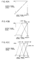
- Figs. 10A, 10B, and 10C are line diagrams showing an example of the dark and light distribution table.
- This table is arranged to indicate a proportionally linear relationship between the image density signal value and the optical reflection density value of an image after recording.
- the image density signals are converted into the dark and light signals by the dark and light distribution circuit on the basis of this dark and light distribution table.
- Each of the image density signals distributed to the dark and light signals, respectively, is binarized by a binarization circuit 6.
- these binarized data are made the discharging signals for each of the recording heads.
- ink is discharged from the ink discharge ports corresponding to each signal value of the recording heads to record a color image.
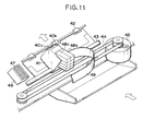
- Fig. 11 is a perspective view showing the principal structure of a color ink jet recording apparatus according to an embodiment of the present invention.
- An ink jet unit 40u for light ink having each discharge port array which discharges light ink independently for black, cyan, magenta, and yellow, respectively, and an ink jet unit 40k for dark ink having each discharge port array which discharges dark ink for black, cyan, magenta, and yellow, respectively, are arranged on a carriage 41 apart from each other at a given distance.
- the carriage 41 is slidably guided on demand by a guide shaft 43 to reciprocate along the guide shaft 43 by the driving force of a carriage motor 45 through a driving belt 44.
- heat generating elements for generating the thermal energy which is utilized for discharging ink.
- Ink is supplied to the corresponding discharge port arrays of each of the ink jet units 40u and 40k from the respective ink cartridges 48u and 48k through given supply passages.
- the interiors of these ink cartridges 48u and 48k are separated by walls to retain yellow, magenta, cyan, and black ink each having the respective densities.
- the control signals and others are transmitted to the ink jet units 40u and 40k through a flexible cable 49.
- a recording material such as a recording sheet or a plastic thin board, is conveyed in the direction indicated by arrows by a feed roller (not shown) and exhaust rollers 42 having a feed motor (not shown) as its driving source.
- a recording is being made on the surface of the recording material facing each of the ink jet units as the units travel.
- the above-mentioned heat generating elements are driven on the basis of the recording signals in accordance with the timing read by an encoder which detects the traveling positions of the carriage 41, thus discharging ink droplets to the recording material in order of dark ink and light ink of each color to enable them to adhere to the recording material for recording an image.
- a recovery unit 46 having a cap unit 47 is arranged in the home position of the carriage 41, which is arranged outside the recording area where a recording is executed by the traveling of the carriage 41.
- the carriage 41 travels to the home position to close the ink discharge formation surface of the ink jet units 40u and 40k corresponding to each of the caps of the cap unit 47; hence preventing any clogging from taking place due to the solidification of ink caused by the evaporation of ink sorbet or the adhesion of foreign material such as dust particles.
- the above-mentioned cap unit 47 is utilized when an idle discharge mode is executed to discharge ink to the interior of the cap unit for the correction of defective discharge and the removal of clogging of the ink discharge ports having low frequency of recording, or when a discharge recovery is processed by sucking ink from the ink discharge ports which have allowed a disabled discharge to occur. Also, arranging a blade in the position adjacent to the cap unit makes it possible to clean the ink discharge port formation surface of the ink jet units.
- Fig. 12 is an exploded perspective view showing the structure of the ink jet units 40u and 40k used for the present embodiment.
- One end of the wiring base board 50 and the wiring part of the heater board 51 are connected with each other, and further, on the other end of the wiring base board 50, a plurality of pads are provided corresponding to each of the electrothermal transducers for receiving the control signals, discharge signals, and the like from the control unit of the apparatus. In this way, the electrical signals from the control unit of the apparatus are supplied to each of the electrothermal transducers.
- a metallic supporting board 52 which supports the reverse side of the wiring base board 50 plainly, also serves as the bottom board of the ink jet units.
- a pressure spring 53 is to press the area in the vicinity of the ink discharge ports of the grooved ceiling board 54 linearly and resiliently. Therefore, this spring comprises a part formed by bending to provide an almost U-letter configuration at its cross-section; the hooking nail which utilizes the escape hole arranged on the base plate; and a pair of hind legs which receive the force working on the spring by the base plate.
- the wiring board 50 and the grooved ceiling board 54 abut upon each other by the force exerted by this spring. Also, the wiring board 50 is mounted on the supporting member by bonding using adhesives or the like.
- ink supply tubes 55 For each of ink, yellow, magenta, cyan, and black, four ink supply tubes 55 are arranged, and on each end of the ink supply tubes 55, an filter 56 is provided.
- the ink supply member 57 is manufactured by a mold formation.
- the liquid passages are also formed to conduct ink from the supply tubes 55 to each of the ink supply inlets arranged on the grooved ceiling board 54.
- the ink supply member 57 is simply fixed to the supporting board 52 in such a manner that two pins (not shown) on the reverse side of the ink supply member 57 are extruded through the holes 58 and 59 arranged on the supporting board 52, and these are thermally bonded for fixation.
- the space between the orifice plate unit 580 and the ink supply member 57 are formed uniformly.
- the sealing agent is filled in from the upper sealing agent inlet prepared on the ink supply member 57.
- the wire bonding is sealed, and at the same time, the space between the orifice plate unit 580 and the ink supply member 57 is sealed.
- the sealing agent flows through the grooves provided for the supporting board 52 to completely seal the space between the orifice plate unit 580 and the front end of the supporting board 52.
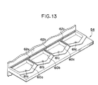
- Fig. 13 is a perspective view showing the above-mentioned grooved ceiling board 54 observed from the heater board 51 side.
- each of the common liquid chambers is partitioned by walls 60a to 60c.
- supply inlets 61a to 61d are provided for supplying ink.
- grooves 62a to 62c are provided on the surface of partition walls 60a to 60c for each of the common liquid chambers, which abuts on the heater board 51. These grooves are conductively connected to the circumference of the grooved ceiling board 54. After the grooved ceiling board 54 is pressed closely to the heater board, the circumferential part is sealed by the aforesaid sealing agent. At this juncture, the sealing agent flows along the above-mentioned grooves to be permeated to fill in the space between the grooved ceiling board and heater board. In this way, it is possible to completely separate the common liquid chambers by the same processes used for the conventional recording head.
- the structure of the grooves differs by the physical properties of the sealing agent, and it is necessary to configure them accordingly.
- Fig. 14A is a schematic view showing the ink discharge port arrays of the ink jet units 40u and 40k observed from the recording material side.
- ink jet units 40u and 40k are used. As described above, these are integrally provided with ink discharge port arrays each for yellow, magenta, cyan, and black for dark ink, and for light ink, respectively.
- the reference marks 70Yk, 70Mk, 70Ck, and 70Kk of the ink jet unit 40k designate the discharge port array to discharge dark ink each for yellow, magenta, cyan, and black, respectively.
- the reference marks 71Yu, 71Mu, 71Cu, and 71Ku of the ink jet unit 40u designate the discharge port array to discharge light ink each for yellow, magenta, cyan, and black, respectively.
- the discharge port array for each color has 32 discharge ports at a pitch of 360 dots per inch (360 dpi). Between each of the colors in these discharge port arrays, a space equivalent to eight dots is provided by the walls between the common liquid chambers.
- Fig. 15 is a schematic view showing the image formation process by use of the ink jet units 40u and 40k shown in Fig. 14A.
- Nth + one line Giving attention to the Nth + one line, it is understandable that after a recording for the dark black Kk and light black Ku is executed by the first scan, a line feed (hereinafter abbreviated to as LF) of the recording material is made for a given amount; a recording for the dark cyan Ck and light cyan Cu is executed by the second scan, followed by an LF; a recording for the dark magenta Mk, and light magenta Mu is executed by the third scan, followed by an LF; and then, a recording for the dark yellow Yk and light yellow Yu is executed by the fourth scan, followed by an LF, thus completing the recording of the Nth + one line.
- LF line feed
- the amount of LF after each recording scan is equivalent to the length of the arrangement of 32 discharge ports of the discharge port array for each color.
- an image is recorded for a 32-discharge port portion.
- the LF amount is set for a length of the discharge port arrangement for each color plus a space between discharge port arrays for each of the colors. The image for the 32-discharge port portion is thus recorded by the four-time recording scans.
- Fig. 14B is a view showing another example of the ink jet units 40u and 40k.
- Fig. 14B there are used one and the same unit having ink discharge arrays for each of the color ink, dark magenta, dark cyan, and dark black in the same unit, and also, one and the same unit having ink discharge arrays for each of the color ink, light magenta, light cyan, and dark yellow.
- the reference numerals 72Kk, 72Mk, and 72Ck of the ink jet unit 40k designate the discharge port arrays to discharge dark ink of black, magenta, and cyan, respectively; and also, 73Yk, 73Mk, and 73Cu of the ink jet unit 40u, the discharge port arrays to discharge light ink of yellow, magenta, and cyan, respectively.
- the dark and light distribution table shown in Fig. 10A is applicable to yellow and black, and the one shown in Fig. 10B is applicable to magenta and cyan.
- the number of discharge ports for 72Kk and 73Yk is two times that of discharge ports for the other colors.
- the discharge port array has 32 discharge ports for dark and light magenta, and dark and light cyan, respectively, while 64 discharge ports for dark black and dark yellow, respectively, both at pitches of 360 dots per inch (360 dpi).
- Fig. 16 is a schematic view showing the image formation process by use of the recording head arranged as shown in Fig. 14B.
- a recording for dark black Kk and dark yellow Yk and an LF are executed by a second scan; a recording for dark cyan Ck and light cyan Cu and an LF are executed by a third scan; and a recording for dark magenta Mk and light magenta Mu and an LF are executed by a fourth scan, thus completing the recording of the Nth + one line.
- the amount of LF after each of the recording scans is equivalent to the width of 32 discharge portion array, and the image recording for the 32 discharge port array portion is executed by the three-time recording scans.
- the recording in dark yellow and dark black is executed every other scans, and a recording of 64-discharge port portion is executed at a time, which is twice as much compared to the one for magenta and cyan.
- the recording speed can be enhanced by varying the amount of LF to a portion equivalent to a 64-dot width.
- Fig. 14C is a view showing an example of still another structure of the ink jet units.
- two ink jet units are used, having ink discharge port arrays for yellow, magenta, cyan, and black, each for the dark ink use and for the light ink use, respectively.
- both ink jet units use dark ink.
- the reference numerals 74Yk, 74Kk, 74Mk, and 74Ck of the ink jet unit 40k designate the discharge port arrays to discharge the dark ink of yellow, black, magenta and cyan, respectively.
- the reference numerals 75Mu and 75Cu of the ink jet unit 40u designate the discharge port arrays to discharge the light ink of magenta and cyan, respectively; and 75Kk and 75Yk, the discharge port arrays to discharge the dark ink of black and yellow, respectively.
- this structure is arranged so that only the dark ink is used for yellow because, having a high brightness, yellow does not make the graininess of its dots conspicuous in the bright image portion, and also for black because it is applied only to the high density portion of an image, making its graininess not conspicuous, either.
- the dark and light distribution table shown in Fig. 10A is applicable to yellow and black, and the one shown in Fig. 10B, to magenta and cyan.
- the discharge port array for each color has 32 discharge ports at a pitch of 360 dots per inch (360 dpi), and there is a space equivalent to a eight-dot portion provided by the walls of liquid chamber for each of the colors between each of the discharge port arrays for the respective colors.
- the discharge port arrays for black and yellow use the two ink jet units, thus having the number of its discharge ports two times the one for other colors. Therefore, a recording for a 64-dot portion is possible at a time. Also, in order to avoid any creation of blank between the yellow and black discharge port arrays for each of the ink jet units, the discharge port arrays for yellow and black are displaced in the unit configuration.
- Fig. 17 is a schematic view showing the image formation process by use of the ink jet recording units structured as shown in Fig. 14C.
- a recording for dark black Kk and dark yellow Yk and an LF are executed by a second scan; a recording for dark cyan Ck and light cyan Cu and an LF are executed by a third scan; and a recording for dark magenta Mk and light magenta Mu and an LF are executed by a fourth scan to complete an image by a three-time recording scans.
- the amount of LF after each of the recording scans is equivalent to a portion of the 32-discharge port width, and the image of 32-discharge port array portion is recorded by three-time recording scans.
- the recordings in dark yellow and dark black are executed every other scans, the second and fourth scans, according to the example shown in Fig. 17.
- a recording for a 64-dot portion which is twice as much, is executed at a time by use of the discharge port arrays in the two ink jet units.
- the amount of LF can be varied to a portion equivalent to a 64-dot width when recording letters in black or a monochrome image, making it possible to enhance the recording speed.
- the ink jet units having ink discharge ports to discharge ink of different colors from the one and the same discharge port formation surface, which is arranged by the provision of divided liquid chambers as in the present embodiment, the number of ink jet units (recording heads) as well as the number of ink cartridges can be reduced, thus making it possible to miniaturize the apparatus.
- the ink jet units used for the present embodiment enables the discharge port arrays for different colors to be fabricated on one and the same discharge port surface in a good precision at a low cost. Therefore, a higher precision and more complicated correction control, which are required for the manufacture of a conventional apparatus, are no longer needed, thus making the provision of a low price possible.
- the ink jet units used for the present embodiment it is preferable for the ink jet units used for the present embodiment to arrange the discharge port arrays for each of the colors on one and the same straight line in order to reduce the steps required for the correction of the ink discharge timing.
- the arrangement is not necessarily limited to the present embodiment. It may be possible to arrange them horizontally or in cross and counter-cross wise.
- discharge port array a plurality of discharge ports to discharge each of color ink or ink each having different densities, which are provided for the ink jet units 40.
- discharge port array is defined for the sake of expression, and it may be possible to call the collection of plural discharge ports a “discharge port group”.
- the ink cartridges according to the present embodiment are also mounted on the carriage as in the case of the ink jet units, but it may be possible to form them integrally with the ink jet units or arrange them so that the cartridges are not mounted on the carriage but to supply ink to the ink jet units through ink supply tubes. Also, it is preferable for the miniaturization of the apparatus to use the cartridges having a plurality of color ink by dividing its interior as in the present embodiment, but it may be possible to use ink cartridges each for a single color without dividing the interior of the cartridge.
- the controlling structure and image signal processing for the color ink jet recording apparatus according to the present embodiment are the same as those described in the foregoing embodiment. Here, the description thereof will be omitted.
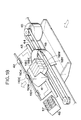
- Fig. 18 is a perspective view showing the principal structure of a color ink jet recording apparatus according to the present embodiment.
- the same reference marks are provided, and the description thereof will be omitted.
- the same is applicable to Fig. 19 and Fig. 20 which will be shown below.
- ink discharge port arrays are arranged for ink jet units 110 for each of colors to discharge the dark ink and light ink, respectively.
- Each of the ink jet units 110K, 110C, 110M, and 110Y are arranged on a carriage 41 at intervals of a given distance in the recording scan direction.
- Fig. 19 is an exploded perspective view showing the structure of the ink jet units 110K, 110C, 110M, and 110Y, which is almost the same as the structure shown in Fig. 12 with the exception of the grooved ceiling board 54.
- Fig. 20 is a perspective view showing the grooved ceiling board 54 of the ink jet units used for the present embodiment observed from the heater board 121 side.
- two common liquid chambers are provided for the dark ink use and the light ink use, and each of the liquid chamber is partitioned by walls 60.
- supply inlets 61a and 61b are provided to supply the dark and light ink, respectively.
- Fig. 21 is a view showing the ink jet discharge arrays of the above-mentioned ink jet units observed from a recording material side.
- one and the same ink jet unit has the ink discharge port arrays each for the dark ink use and light ink use, and such an ink jet unit is used for each of ink, yellow, magenta, cyan, and black, respectively.
- the reference numerals 143Yu, 142Mu, 141Cu, and 140Ku designate the discharge port arrays to discharge the light ink, and 143Yk, 142Mk, 141Ck, and 140Kk, the discharge port arrays to discharge the dark ink.
- Each of the discharge port arrays corresponding to each of the dark and light ink has 64 discharge ports at a pitch of 360 dots per inch (360 dpi), and there are spaces each equivalent to a portion of eight-discharge ports provided by the walls of the common liquid chambers between each of the colors.
- Fig. 25 is a schematic view showing the image formation process by use of the ink jet units shown in Fig. 21.
- a recording for dark black, dark cyan, dark magenta, and dark yellow and an LF are executed by a first scan; and a recording of light black, light cyan, light magenta, and light yellow and an LF are executed by a second scan.
- the recording on the Nth + one line is completed by two-time recording scans just by the first and second scans, and at this juncture, the amount of LF after each of the recording scans is equivalent to a 64-discharge port portion; thus recording the image equivalent to a portion of the 64-discharge port array by the two-time recording scans.
- Fig. 22 is a schematic view showing another structural example of the ink jet units.
- one and the same ink jet unit has ink discharge port arrays for dark ink use, medium ink use, and light ink use, respectively, and such an ink jet unit is used for each of ink, yellow, magenta, cyan, and black, respectively.
- the dark and light distribution table shown in Fig. 10C is applicable.
- the reference numerals 153Yu, 152Mu, 151Cu, and 150Ku designate the discharge port arrays to discharge the light ink; 153Ym, 152Mm, 151Cm, and 150Km, the discharge port arrays to discharge the medium ink; and 153Yk, 152Mk, 151Ck, and 150Kk, the discharge port arrays to discharge the dark ink.
- Each of the discharge port arrays corresponding to ink having each of the densities has 32 discharge ports at a pitch of 360 dots per inch (360 dpi), and there is a space equivalent to a portion of eight dots provided by the walls of the common liquid chambers between each of the colors.
- a recording for dark black, dark cyan, dark magenta, and dark yellow, and an LF are executed by a first scan; a recording for medium black, medium cyan, medium magenta, and medium yellow, and an LF are executed by a second scan; and a recording of light black, light cyan, light magenta, and light yellow, and an LF are executed by a third scan, thus completing an image by three-time recording scans.
- the amount of LF after each of the recording scans is equivalent to a 32-discharge port portion, and the image for a potion of the 32-discharge port arrays is recorded by the three-time recording scans.
- ink having the medium density is used in addition to the dark and light ink, the graininess becomes less conspicuous in all the tonal areas. Further, it becomes possible to switch over ink having each of the densities smoothly, thus preventing the false contours to be created to enable a smoother tonality to be reproduced.
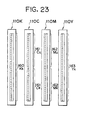
- Fig. 23 is a schematic view showing still another structural example of the ink jet units.
- the reference numerals 162Mu and 161Cu designate the discharge port arrays to discharge the light ink, and 163Yk, 162Mk, 161Ck, and 160Kk, the discharge port arrays to discharge the dark ink.
- the number of discharge ports in the discharge port arrays 160Kk and 163Yk are two times the number of discharge ports for the other colors.
- an yellow image has a high brightness, and no dot graininess is conspicuous in the bright image part, and also, a black image is used only for a part having a high density, and its graininess is not conspicuous, either, only the ink each having high densities are used for black and yellow.
- the dark and light distribution table shown in Fig. 10A is applicable to yellow and black, and the one shown in Fig. 10B is applicable to magenta and cyan.
- Fig. 26 is a schematic view showing the image formation process by use of the ink jet units shown in Fig. 23.
- a recording for dark black, dark cyan, dark magenta, and dark yellow and an LF are executed by a second scan
- a recording for light cyan, and light magenta, and an LF are executed by a third scan to complete an image by two-time recording scans by the above-mentioned second and third scans.
- the amount of LF after each of the recording scans is equivalent to a portion of 64-discharge port arrays, and the image for the portion of the 64-discharge port arrays is recorded by the two-time recording scans.
- the dark yellow and dark black are recorded only by the second scan, which is executed after every one scan, and compared to magenta and cyan, a recording for a portion of 128-discharge arrays, which is twice as much, is executed at a time.
- Fig. 24 is a schematic view showing a further structural example of the ink jet units.
- one and the same ink jet unit has the ink discharge port arrays each for the dark ink use and the light ink use as well as each having a different amount of ink discharge, and such a unit is used, respectively, for ink of each color having each density.
- the reference numerals 173Yus, 172Mus, 171Cus, and 170Kus designate the discharge port arrays to discharge small droplets each having a small amount of discharge for the light ink of the respective colors, and 173Yul, 172Mul, 171Cul, and 170Kul, the discharge port arrays to discharge large droplet having comparatively small amount of discharge for the respective colors.
- the reference numerals 173Yks, 172Mks, 171Cks, and 170Kks designate the discharge port arrays to discharge small droplets having a small amount of discharge for each of the colors of dark ink, and 173Ykl, 172Mkl, 171Ckl, and 170Kkl, the discharge port arrays to discharge large ink droplets having a comparatively large amount of discharge for each of the colors of dark ink.
- the amount of a small ink droplet is approximately 20 pl, and the amount of a large ink droplet is approximately 40 pl.
- Fig. 27 is a schematic view showing the image formation process by use of the ink jet units shown in Fig. 24.
- a recording by the small droplets of dark black, dark cyan, dark magenta, and dark yellow, and an LF are executed by a first scan; a recording by the large droplets of dark black, dark cyan, dark magenta, and dark yellow and an LF are executed by a second scan; a recording by the small droplets of light black, light cyan, light magenta, and light yellow and an LF are executed by a third scan; and a recording by a large droplets of light black, light cyan, light magenta, and light yellow and an LF are executed by a fourth scan.
- the above-mentioned four-time recording scans, the Nth + one line are completely recorded.
- the amount of LF after each of the recording scans is equivalent to a portion of 32-discharge port arrays, and the image for the portion of 32-discharge port arrays is recorded by four-time recording scans.
- ink of the same color series can be grouped in one ink jet unit, making it possible to share the ink cartridge as well as to reduce the possibility of the creation of color mixture which tends to occur when a discharge recovery is executed.
- the discharge port arrays for the ink having a low density (light ink) at the upper side, and those for the ink having a high density (dark ink) at the lower side it is possible to prevent the ink mixture from taking place between different colors even if the dropping flow of ink occurs in operating the discharge recovery by suction.
- the present example uses the ink jet units provided integrally with the ink discharge ports to discharge ink of different colors on one and the same discharge port formation surface by dividing the common liquid chamber; hence making it possible to reduce the number of ink jet units (recording heads) as well as the number of ink cartridges, and then, to miniaturize the apparatus.
- the ink jet units used for the present embodiment enable the discharge port arrays for different colors to be formed on one and the same discharge port surface in a good precision at a low cost. Therefore, a higher precision and a more complicated correction control, which are required for the conventional apparatus, are no longer needed; hence making the provision of a low price possible.
- the ink jet units used for the present embodiment it is preferable for the ink jet units used for the present embodiment to arrange the discharge port arrays for each of the colors on one and the same straight line in order to reduce the steps required for the correction of the ink discharge timing.
- the arrangement is not necessarily limited to the present embodiment. It may be possible to arrange them horizontally or in cross and counter-cross wise.
- the ink cartridges according to the example of this variation can be mounted on a carriage as in the ink jet units, but it may be possible to integrate the ink cartridges with the ink jet units or to supply ink to the ink jet units through ink tubes from the ink tank retaining each ink which is not mounted on the carriage. Also, as in the present embodiment, it is preferable to use the cartridge containing ink of plural colors by dividing its interior in order to miniaturize the apparatus, but it may be possible to use ink cartridges for each of single colors without dividing its interior.
- Fig. 28 is a schematic view of an ink jet unit according to another example of variation of the first embodiment observed from a recording material side.
- the ink jet unit uses one and the same ink jet unit in which the ink jet discharge port arrays are integrally arranged for all the ink colors to be used for recording.
- a reference numeral 210Yu designates a discharge port array to discharge a color ink of light yellow
- 210Mu a discharge port array to discharge a color ink of light magenta
- 210Cu a discharge port array to discharge a color ink of light cyan
- 210Ku a discharge port array to discharge a color ink of light black
- 210Yk designates a discharge port array to discharge a color ink of dark yellow
- 210Mk a discharge port array to discharge a color ink of dark magenta
- 210Ck a discharge port array to discharge a color ink of dark cyan
- 210Kk a discharge port array to discharge a color ink of dark black.
- the discharge port array for each of color ink has 32 discharge ports at a pitch of 360
- a recording in dark black and an LF are executed by a first scan; in light black and an LF by the next second scan; in dark cyan and an LF by a third scan; in light cyan and an LF by a fourth scan; in dark magenta and an LF by a fifth scan; in light magenta and an LF in a sixth scan; in dark yellow and an LF by a seventh scan; and in light yellow and an LF in a eighth scan.
- the recording is completed for a portion equivalent to the discharge port array in each line.
- the amount of LF after each of the recording scans is equivalent to a portion of 32-discharge port arrays, and the image is recorded for a portion of 32-discharge arrays by eight-time recording scans.
- the recording for all the colors is not executed at a time as in the foregoing embodiments, thus making it possible to obtain an excellent image having a lesser deterioration of image due to ink blur or the like.
- the positions where the recording scans for each of the colors are joined are not identical. Unlike the description in conjunction with Fig. 28, the position in one color differs from the other. As a result, it becomes possible to obtain an effect to reduce the creation of the joint streaks by the recording scans.
- the ink jet unit enables the ink discharge port arrays for all the colors to be formed on one and the same discharge port formation surface in a good precision. there is no problem of any registration deviation between each of the colors.
- the discharge port arrays for all the colors are on a straight line as in the present embodiment because this arrangement does not require any correction of discharge timing between the respective colors.
- the arrangement is not necessarily limited to the present embodiment. It may be made horizontally or cross and counter-cross wise.
- each of the discharge port arrays is arranged in cross and counter-cross wise, there is no need for the provision of spaces between each of the colors; making it possible to dispense with any complicated control for sheet feeding.
- the recording speed can be enhanced by varying the number of discharge ports as required.
- the present embodiment uses the ink jet unit provided integrally with the ink discharge ports to discharge ink of different colors on one and the same discharge port formation surface by dividing the common liquid chamber; hence making it possible to reduce the number of ink jet units (recording heads) as well as the number of ink cartridges, and then, to miniaturize the apparatus. Also, a higher precision and a more complicated correction control, which are required for the conventional apparatus, are no longer needed; hence making the provision of a low price possible.
- the ink cartridge may be integrated with the ink jet unit or to supply ink to the ink jet unit through ink tubes from the ink cartridge which is not mounted on the carriage.
- the cartridge containing ink of plural colors it is preferable to use the cartridge containing ink of plural colors by dividing its interior in order to miniaturize the apparatus, but it may be possible to use ink cartridges for each of single colors without dividing its interior.
- Fig. 29 illustrates the structure of an integrated type ink jet cartridge in which the ink jet units 224 for four colors - yellow, magenta, cyan, and black - are integrally assembled by a frame 220.
- the four ink jet units 224 are installed in the frame 220 at given intervals, and fixed therein in a state that its registration in the direction of the discharge port arrays is already adjusted.
- a reference numeral 221 designates the frame cover, and 222, a connector which connects the pads provided for the wiring base board 120 of the four ink jet units 224 and electrical signals transmitted from the apparatus main body.
- the wiring base board 120 and the connector 222 are coupled by electrodes 223.
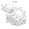
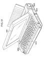
- Fig. 30 shows a state that the above-mentioned integrated type ink cartridge 222 is mounted on a carriage.
- Each of the ink tanks 118 is partitioned into two chambers, upper and lower, by a partition 230.
- the upper chamber light ink is filled while in the lower chamber, dark ink is filled.
- the ink jet cartridge 222 and the four ink tanks 118 each containing yellow, magenta, cyan, and black, respectively, abut upon each other for coupling, so that ink is supplied from the ink tanks 118 to the corresponding ink discharge port arrays.
- the recording for all the colors is not executed at a time as in the foregoing embodiments, thus making it possible to obtain an excellent image having a lesser deterioration of image due to ink blur or the like.
- the actual ink jet unit there are spaces between each of the colors, and the positions where the recording scans for each of the colors are joined are not identical in recording in the respective colors, and the positions become different. As a result, it becomes possible to obtain an effect to reduce the creation of the joint streaks by the recording scans.
- the integrated type ink jet units according to the present embodiment it is made possible for the integrated type ink jet units according to the present embodiment to arrange in a good precision a plurality of ink discharge port arrays formed on one and the same discharge port formation surface in a good precision for assembling an integrated cartridge. Therefore, the problem of the registration deviation between each of the ink jet units can be solved in order to reduce the load to the correction control. Also, the electrical connection can be shared by each of the ink jet units to reduce the number of connecting points with the apparatus main body.
- the discharge port arrays for all the colors are on a straight line as in the present embodiment because this arrangement does not require any correction of discharge timing between the respective colors.
- the arrangement is not necessarily limited to the present embodiment. It may be made horizontally or cross and counter-cross wise.
- the recording speed can be enhanced by varying the number of discharge ports as required.
- the ink cartridge may be integrated with the ink jet unit or to supply ink to the ink jet units through ink tubes from the ink cartridge which is not mounted on the carriage.
- the cartridge containing ink of plural colors it is preferable to use the cartridge containing ink of plural colors by dividing its interior in order to miniaturize the apparatus, but it may be possible to use ink cartridges for each of single colors without dividing its interior.
- the present embodiment enables the apparatus to be miniaturized. Also, any higher apparatus precision and complicated correction control, which are required for the conventional apparatus, are no longer needed, hence making the provision of a low price possible.
- a recording is executed by arranging the pixel positions to be recording by each scan so that a pixel group comprising one vertical pixel and one horizontal pixel becomes complementary by several times of scanning.
- a recording head having eight discharge ports each arranged vertically to discharge dark ink and light ink is exemplified for the description of the present embodiment.
- four discharge ports, in the lower half for the light ink portion, are used among the entire 16-ink discharge port array.
- the pixel arrangement to be recorded is such that a pixel group of 1 x 2 pixels is arranged alternately in a cross and counter-cross form.
- the above-mentioned discharge ports record a half of the entire pixels which can be recorded (that is, to record the pixels by thinning them to a half).
- the pixels to be recorded is the area of the four-pixel width which is not recorded by the first recording scan, and the following portion in which a pixel group of 1 x 2 pixels is arranged in the cross and counter-cross form among the image area of the four-pixel width which follows the recorded area. This portion is in a complementary position in the area where it is superposed with the first recording scan.
- the recording sheet is again fed for a portion equivalent to a four-pixel width while the recording head is returned to the start position of recording. Then a third recording scan is executed.
- the discharging ports used here are the entire eight discharge ports for the light ink, and the four discharge ports in the lower half of the discharge port array for the dark ink.
- the pixel arrangement to be recorded at this juncture are the pixel group of 1 x 2 pixels arranged alternately in the same manner as in the first recording scan.
- the above-mentioned discharge ports record a half of the enter pixels by thinning them accordingly.
- the entire discharge ports of the recording head unit are used to record the pixels alternately arranged with 1 x 2 pixels by thinning reversely to the third recording scan. Then, with this recording scan, the recording required for the first pixel recording is completed. Thereafter, the recording is repeated in the same manner to compete an image.
- a thinned pattern in which 1 x 2 pixels are arranged alternately is used, but the pattern is not limited to this embodiment. It may be possible to record by use of a pattern in which the entire pixels are thinned in a cross and counter-cross form.
- the structure of the recording head unit is not limited to the present embodiment. Any one of the structures described in the above-mentioned embodiments may be applicable.
- all the above-mentioned embodiments can be an effective means not only for the color image recording, but also for the recording of a monochromic image such as a gray scale recording.
- the frequency of use of the dark and light ink of the same color series is substantially equal, thus making it possible to exchange the ink jet unit which is integrally formed with an ink tank without wasting ink so much.
- a sixth embodiment and those given thereafter will enable the color unevenness, density unevenness, and streaks to be reduced sufficiently by utilization of the arrangement relationship of each of the ink discharge port arrays shown in each of the foregoing embodiments.
- the ink jet unit which demonstrates the effects brought about by the integration of each of the ink discharge port arrays as in each of the foregoing embodiments or to use the structure which is the same as those described in the foregoing embodiments in the arrangement relationship of each of the ink discharge port arrays but each of them is not integrated.
- Fig. 32 is a schematic view showing the structure of an ink jet unit (hereinafter may be referred to as recording head) used for the present embodiment according to the present invention.
- the independent recording head for each of four colors, black (K), cyan (C), magenta (M), and yellow (Y), has a total of 16 discharge ports, eight discharge ports each for the dark ink and light ink, respectively.
- the arrangement of the discharge ports for each of ink for this recording head is the same as the discharge port arrangement shown in Fig. 21. It may be possible to integrate each of the discharge port arrays.
- the recording scan and sheet feeding are executed.
- the sheet feed is an amount equivalent to a portion of four-discharge port width per recording scan.
- the recording sheet is fed in the direction from the light ink recording area to the dark ink recording area. Therefore, the recording is always executed in such an order that the dark ink image is recorded after the completion of the recording of the light ink image. If the structure is arranged in this way so that the discharge port arrays are arranged in one line in the sheet feeding direction for each of the dark and light ink, there is no possibility that the order in which each of the dark and light ink is impacted is not reversed in the bidirectional recording, forward and backward paths. As a result, it is possible to prevent the dark and light unevenness from being created in advance due to the order of impacting ink each having different densities.
- a divided recording is executed further by use of the recording head which discharges ink each having different densities with respect to each of plural kinds of ink having different colors. Therefore, the effects of the divided recording can be demonstrated even in the structure in all the kinds of ink discharge port arrays are arranged in the direction of the recording scan as shown in Fig. 7. Nevertheless, it is often encountered that the unfavorable color unevenness cannot be completely eliminated by the provision of such a structure as this.
- the amount of an ink droplet is designed so that the dot area formed by the ink droplet impacting upon the surface of a recording sheet spreads slightly wider than the area given to each pixel on the surface of the recording sheet. This is a precaution to avoid any white portion of the sheet to appear when the dot area on the surface of the sheet is smaller than the area where the printing ratio is 100%.
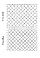
- the divided recording method when the divided recording method is applied, more than a 50% of the area of the recording medium (recording sheet) is covered as shown in Fig. 33A, although in this method, approximately 50% is recorded out of the pixel numbers to be recorded.
- the dark and light ink, and, further, two or more colors of dark and light ink are recorded on one and the same pixel for the mixed color recording.
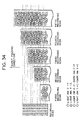
- Fig. 34 shows the state that a uniformly green image is recorded in the present embodiment.
- the uniformly green image referred to in this respect is an image which is recorded in cyan and yellow both having the dark and light ink.
- the image density signal inputted for this image indicates a duty between 128 and 255.
- the pixel positions to be recorded by each of the recording scans are arranged so that the pixel group of one vertical pixel x two horizontal pixels are arranged alternately in a cross and counter-cross form.
- a first recording scan the four discharge ports in the lower half to discharge the light ink having a low image density among all the 16 discharge ports in the recording head.
- the pixel arrangement to be recorded at this juncture is the pixel group of 1 x 2 pixels which is arranged alternatly, and with the above-mentioned discharge ports, a half of the entire recordable pixels is recorded.
- the first recording scan since the recording is executed by the recording head which scans in the forward direction, the ink is impacted on each of the recording pixels in order of cyan and yellow when the uniformly green image is recorded. Therefore, the pixels recorded by the first recording scan bring about a green image having the stronger cyanic coloring.
- the recording sheet is fed in the direction indicated by an arrow in Fig. 34 for a portion equivalent to four-pixel width.
- a recording is executed in the backward direction of the recording scan by use of all the eight discharge ports on the discharge port array to discharge the light ink.
- the pixels to be recorded at this juncture are of the area of four-pixel width which is not recorded in the first scan, and the part where the pixel group of 1 x 2 pixels arranged also alternately in the image area of the four-pixel width which follows it immediately.
- the recording is executed in the backward scan. Therefore, ink is impacted on the recording pixels in order of yellow and cyan.
- the pixels recorded by the second recording scan bring about a green image having a stronger yellowish coloring.
- the ink used for the first and second recording scans are those having the light density. The difference in the coloring due to the order of ink impacting is not so conspicuous.
- a third recording scan is executed after the recording sheet is fed for a portion equivalent to four-pixel width.
- the discharge ports to be used here are all the eight discharge ports on the discharge port array to discharge the light ink, and the four discharge ports on the lower half of the discharge ports to discharge the dark ink. Since this recording scan is again in the forward direction, ink is impacted in order of cyan and yellow in the area of the second and third image areas, which is recorded by the light ink; thus obtaining a green image having a strong cyanic coloring. In contrast, in the first image area, the light ink printing is already completed, and the priority color has already been set. Hence, even if the dark ink is impacted in order of cyan and yellow, it does not result in setting the priority color, but only in making the green density more conspicuous as a whole.
- a fourth recording scan after another sheet feeding the recording is executed in the first image area by use of the entire discharge ports for the first time. Since this recording scan is again on the backward path, ink is impacted in order of yellow and cyan. As described for the third recording scan, the light ink has been impacted already on the first image area and the second image area. This recording is made on them. Therefore, there is almost no influence made by the impacting order of the dark ink. Only the green density in both image areas is enhanced as a whole. Then, with this recording scan, the recording on the first image area is completed. In the third and fourth image areas, the priority color has already been set for the recorded pixels by the impacting order of ink as in the recording scans up to now.
- a light ink image is completed by the first two-time recording scans by the use of the recording head shown in Fig. 32 in the entire image areas which are in series each by four-pixel width, and then, the dark ink image is completed by the following two-time recording scans. Therefore, even with the recording method which uses plural dark and light ink having different densities, it is possible for the present embodiment to remove the causes themselves which allow the dark and light unevenness to appear in the conventional examples.
- a structure is arranged so that the dots having different tonality are recorded in the forward and backward paths.
- the divided recordings are executed, and at the same time, the pixels to be recorded are arranged in a unit of 1 x 2 pixels; hence making it possible to suppress more the ink permeation to the other areas as compared with the event described in conjunction with Figs. 33A and 33B.
- the ratio of the area occupied by the dots recorded in the forward path and the ratio of the area occupied by the dots recorded in the backward path are substantially identical; thus enabling an image of a better quality to be obtained.
- the two harmful events, the dark and light unevenness, and the color unevenness, which tend to occur in the bidirectional recording, that is, recording is executed both in the forward path and backward path are solved by the structural application of the discharge port arrays for each of ink colors with respect to the former event, and by the application of the divided recording and structural arrangement of the pixels with respect to the latter.
- the head structure is arranged so that the recording in the dark ink is executed subsequent to the recording in the light ink.
- the impacting order of dark and light ink itself is not limited to this arrangement. In other words, it may be possible to obtain the effects of the present invention by making an arrangement so that the positions of the light ink nozzles and the dark ink nozzles are inverted.
- the recording head having the arrangement that the light ink is used earlier is considered more suitable for recording a color image.
- the head recording in the dark ink earlier can be a structure which is more suitable for the letters, images, and others to be recorded in black with a high density.
- a color ink jet recording apparatus having a recording head to discharge the dark and light ink can eliminate the color unevenness, and dark and light unevenness due to the impacting order of ink even in executing the bidirectional recording by arranging ink of each color in the scanning direction of the recording head, and the dark and light ink discharge ports in the sheet feeding direction; enabling an excellent image to be obtained in this way.
- the description will be made of a seventh embodiment according to the present invention.
- the dark and light unevenness is solved by the arrangement of the head structure, and the color unevenness, by the application of the divided recording method in the above-mentioned sixth embodiment
- the dark and light unevenness is solved by the application of the divided recording method, and the color unevenness, by the arrangement of the head structure.
- Fig. 36 shows the structure of the recording head according to the present embodiment.
- this example of a variation also used a recording head having 16 discharge ports arranged in a line.
- the dark ink head and the light ink head are independent from each other and are arranged in parallel in the direction of recording scan.
- four discharge ports are arranged for each of the colors toward the sheet feeding direction.
- the order of the recording colors is set: black, cyan, magenta, and yellow.
- the arrangement order in the sheet feeding direction is not necessarily limited to only one. Also, in the present example, there are only four discharge ports for each color and each density. Therefore, the amount of sheet feed is equivalent to a two-pixel width in order to execute the divided recording.
- Fig. 37 shows the process of a recording in the present embodiment.
- a case where a uniformly green image is recorded in cyan and yellow is also exemplified.
- the leading end of the recording sheet is set at the position of the black discharge ports if any black data are present.
- the recording sheet is fed to the position of the cyan discharge ports as shown in Fig. 37.
- the recording sheet is set at the position of two discharge ports in the lower half of the cyan ink discharge ports in a first recording scan.
- the dark cyan ink and light cyan ink are impacted on the recording pixels in that order.
- the dark ink being impacted first the recorded pixels are such that around the cyan pixels having a high density and clear dot contour, large cyanic dots having a low density surround weakly.
- the recording sheet is fed for a portion equivalent to a two-pixel width, and next, the second recording scan follows.
- the pixel arrangement to be recorded at a time in each of the recording scans uses the pixel group of 1 x 2 pixels arranged alternately as in the sixth embodiment.
- the second recording scan is in the backward path, the light cyan ink and the dark cyan ink are impacted on each of the pixels in that order.
- the dark ink dots recorded subsequent to the light ink having already been impacted are permeated largely around the light ink dots; thus the pixels becoming even having the density which is lower than the density of the dots obtainable in the recording scan in the forward path.
- the cyan recording is completed by the two-time recording scans so far.
- the first image area there are mixed the high density cyanic dots and the low density cyanic dots approximately in halves.
- a half of cyanic dots are recorded in the backward path at that time.
- the first image area is positioned facing the magenta discharge port array. Therefore, no actual recording is executed.
- the cyanic dots are recorded one after another in each of the image areas facing the cyan discharge port array.
- the first image area where the cyanic dots are recorded will be recorded next in the fifth recording scan when this area is positioned facing the yellow discharge port array.
- the yellow ink is impacted on the dots already recorded in the cyan ink in order of dark and light ink. If the ink should be impacted on a white sheet in that order, the recorded pixels become highly densified yellowish pixels.
- the recording is executed on the pixels in which the cyan ink has already been absorbed. Therefore, the yellow ink is largely permeated around beneath the cyan ink. Here, no difference arrears in the dot configurations and in its darkness and lightness.
- the recording is executed only when each of the image areas is positioned facing the cyan discharge port array, and positioned facing the yellow discharge port array after two scans.
- the recording in yellow is executed only after all the recording areas are completely recorded in cyan. Therefore, the harmful color unevenness occurring in the reciprocal recording, which has been described in conjunction with a conventional example, is eliminated by the arrangement of the recording head structure in the present embodiment.
- the color unevenness and dark and light unevenness due to the impacting order of ink in the bidirectional recording can be eliminated according to the present embodiment by arranging the dark and light ink discharge ports in the direction of recording scan, and also, the discharging ports to discharge the respective color ink in the sheet feeding direction.
- the order of ink color arrangement in the sheet feeding direction is not limited to the one described in the present embodiment, too. It may be possible to obtain the same effect of the present invention in any arrangement.
- the black ink is brought to the top order with an intention to maximize the density and resolution of black ink among four colors to be used. Making the density and resolution of the black ink higher leads to the provision of clearer letters and images in black.
- a plurality of recording heads are used so that each of the heads corresponds to each color or density.
- only one recording head is employed.
- the ink discharge ports for all the densities and colors are arranged in advance in the recording head, and then, the structure is arranged to integrate them as a body.
- Fig. 38 is a schematic view showing the structure of a recording head to be used for the present embodiment.
- a recording in a color is completed by a total of 16 discharge ports, eight discharge ports each for discharging the dark ink and light ink for each of the color ink.
- the discharge port group for each color is arrange in order of black (K), cyan (C), magenta (M), and yellow (Y), but in this case, the adjacent discharge port groups for the respective colors are arranged to superpose them in a portion of one discharge port each other.
- the horizontal solid lines on the head represent a state of sheet feeding to indicate the positions where the leading pixels of the recording sheet arrive at by the sheet feeding scans one after another per four-pixel width.
- the leading pixels are being positioned according to color in the different parts of the eight discharge ports arranged for each of the colors, if the structural arrangement of the discharge ports is employed as in the present embodiment. In other words, the leading pixels can be positioned at the joint section of the divided recording in black, but these pixels are not positioned at such a joint section in cyan, magenta, and yellow.
- Fig. 39 shows the recording process according to the present embodiment.
- Fig. 39 illustrates a state that a uniformly green image is being recorded.
- the ink discharge ports for ink of different colors are arranged in the sheet feeding direction as in the foregoing seventh embodiment.
- the image area referred to here is a four-pixel area which the recording head for each color records at the same time, that is, an area between the joint sections for each of the colors.
- the image areas are structured by each of the colors, which differ from each other unlike the image area in the foregoing embodiments.
- Fig. 40 illustrates the joint section (image area) between the recorded image and the respective colors after the sixth recording scan shown in Fig. 39.
- the respective joint section image area
- the joint section appears in the positions in which the respective colors are displaced by one pixel each.
- the positions of the discharge ports in the recording head are arranged to superpose one discharge port with each other for each of the colors in order to make the joint sections different per color, but the structural arrangement of the discharge ports to differentiate the joint sections is not necessarily limited to this arrangement.
- the joint section for each color may be arranged in various positions if the number of discharge ports which participate in recording is increased, and the amount of sheet feeding becomes greater accordingly.
- the order of ink color arrangement in the sheet feeding direction is not necessarily limited to the one described herein. It may be possible to obtain the same effect by any arrangement.
- the image can be recorded more smoothly, it is possible to anticipate the effects produced favorably on the elimination of the color unevenness and dark and light unevenness due to the ink permeation as has been described.
- Figs. 41A to 41D are views illustrating the ink suction operation by an ink jet recording apparatus to which the present invention is applicable, and is a cross-sectional view schematically showing the cap unit shown in Fig. 18.
- a porous ink absorbent 20 is provided in the interior of each capping 117. As shown in Fig. 41A, this ink absorbent 20 is arranged so that it is positioned in the vicinity of the discharge port formation surface 21 at the time of capping. In this respect, a portion 30 indicated by the highly densified slant lines in Figs. 41A to 41D designates ink absorbed (sucked) from the discharge ports.
- Fig. 41A illustrates a state that a suction pump is operated while the cap 117 abuts closely on the discharge port surface 21 to generate a negative pressure in the cap 117 through a tube 27; thus sucking ink from each of the discharge ports, and then, suspending the operation of the suction pump.
- the negative pressure in the suction pump is almost released because a certain amount of ink has been sucked. In other words, the negative pressure is reduced to the extent that the meniscus of each discharge port is not broken.
- the carriage is finely shifted in the right-hand direction in Fig. 41A in order to provide a space 31 between the cap 117 and the discharge ports.
- the fine amount of shift of the carriage is set at an appropriate amount which is more than the range allowing the cap 117 to execute the air-tight closing.
- Figs. 42A and 42B are schematic views showing the state of the carriage which finely shifted as described above.
- Fig. 42A shows the state before the shift.
- Fig. 42B shows the state after the shift.
- Fig. 41B shows the state in the interior of the cap immediately after the carriage is finely shifted from the state shown in Fig. 41A as described above.
- the suction pump is again operated when the space 31 is prepared.
- the state of the interior of the cap at that time is shown in Fig. 41C.
- the suction pump is again operated in the state shown in Fig. 41B, only the ink in the cap 117 is sucked through the tube 27 as shown in Fig.
- the cap is in a leaking state (released).
- the porous ink absorbent 20 provided in the cap 117 is restored to a state capable of sucking ink.
- the porous ink absorbent 20 is closely positioned to the discharge port surface 21, most of all the ink on the discharge port formation surface 21 is absorbed by the ink absorbent 20. The ink thus absorbed into the ink absorbent 20 is also sucked through the tube 27.
- the carriage is returned to the original position.
- the carriage is returned to the positions shown in Figs. 41A and 42A so than the ink absorbent 20 which has regained its ink absorbing capability sufficiently is in the state that it approaches closely the entire area of the discharge port formation surface 21. In this way, it is possible to reduce more the ink remains on the discharge port formation surface 21.
- the ink remains on the discharge port formation surface are reduced; thus making it possible to prevent the color mixture from being created.
- the carriage is shifted in the main scanning direction in the above-mentioned embodiment, but it may be possible to shift it in the sub-scanning direction. Further, to provide the space 31, the structure may be arranged to shift the cap side vertically, horizontally, forward or backward, diagonally or the like instead of shifting the carriage.
- Figs. 44A to 44D are schematically cross-sectional views of a cap unit for illustrating another example of suction operation.
- a porous ink absorbent 52 is arranged in the interior of each cap 117.
- the capacity of the ink absorbent 52 is set at a value greater than the suction amount (the amount of forcibly exhausted ink per operation) of the suction pump, or at a value greater than the volume of the ink passages in the ink jet units. Then the foregoing ink absorbent 52 is arranged so that it is positioned in the vicinity of the discharge port formation surface 81 at the time of capping as shown in Fig. 44A.
- a portion at 53 in Figs. 44A to 44D indicates the ink which has been absorbed (sucked) from the discharge ports.
- Fig. 44A illustrates a state that a suction pump is operated while the cap 117 closely abuts on the discharge port formation surface 81, and a negative pressure is created in the cap 117 through a tube 19, thus ink 52 is being sucked from each of the discharge ports. After that, at a given timing, the recording head and the cap 117 are separated as shown in Fig. 44B. Then a space 54 is formed between them.
- the time when the negative pressure is almost released by the suction of a given amount of ink with the operation is the suction pump being suspended, or the time when a given amount of ink has been sucked even in a state that the negative pressure is still active in the cap 117, is selected among others.
- the ink sucked from the recording head by the suction pump is being transferred to a waste ink tank (not shown) through a tube or ink passages.
- the waste ink tank may be structured by a porous ink absorbent which absorbs and holds the waste ink.
- the volume of the porous ink absorbent 52 is set, as described earlier, at a value greater than the amount of suction (the amount of forcibly exhausted ink per one operation) or at a value greater than the volume in the ink passages in the recording head.
- the ink 53 between the discharge port formation surface 81 and the cap 117 is carried to the aforesaid ink absorbent 52 side by the suction force exerted by the ink absorbent 52 as shown in Fig. 44C. Consequently, as shown in Fig. 44D, it is possible to complete the suction recovery operation in a state that no ink remains on the discharge port formation surface 81 of the recording head. In this way, it is possible to prevent ink of different colors from being mixed because the suction recovery operation terminates in the state that no ink remains on the discharge port formation surface 81.
- the porous ink absorbent 52 in the cap, it is possible to provide a directionality (direction toward the suction pump side from the discharge port surface 81) for the ink flow in the cap 117 when sucked.
- a directionality direction toward the suction pump side from the discharge port surface 81
- ink of different colors from being mixed, which occurs otherwise if the ink adhering to the discharge port formation surface 81 should be allowed to flow into the discharge ports.
- the area recordable by one scanning is divided, and further, the pixels in the divided areas are recorded by the divided recording with the plural numbers of scanning.
- ink jet units recording head
- recording head The structure of ink jet units (recording head) used for the present embodiment is the same as the structure shown earlier in Fig. 19.
- the perspective view of the grooved ceiling board 54 of the ink jet units observed from the heater board 121 is the same as the view shown earlier in Fig. 20.
- the above-mentioned structure of the head unit has already been described. Therefore, the description thereof will be omitted.
- the structures of the color ink jet recording apparatus and the image processing unit are also the same as those of the embodiment described earlier.
- the divided recording method such as described earlier is not adopted. It is always set so that a recording area is recorded 100% by a dark ink having a high image density in the forward scan, and then, after its completion, the recording area is recorded 100% by a light ink having a low image density in the backward scan without executing any sheet feeding scan.
- a printing is executed in the forward scan in the dark ink of black ⁇ cyan ⁇ magenta ⁇ yellow, and in the backward scan, the printing is completed in the light ink in order of yellow ⁇ magenta ⁇ cyan ⁇ black. In principal, therefore, no density unevenness appears due to the impacting order of ink in all the colors and densities.
- Fig. 46 illustrates a state where a uniformly green image is being recorded in such a condition as this.
- the uniformly green image referred to here is an image which is recording in both dark and light ink of cyan and yellow.
- the input image density signal indicates a duty from 128 to 255.
- a state is set for the sake of explanation that all the pixels are recorded by the above-mentioned four kinds of ink.
- the recording of the image area equivalent to the head width is completed.
- the ink is impacted in order of dark ink cyan, dark ink yellow, light ink yellow, and light ink cyan.
- a uniform image is obtained in the priority color of the dark ink cyan in which the first recording has been made.
- the recording sheet After a pair of reciprocal recording scans, the recording sheet is fed in the direction indicated by an arrow for a portion equivalent to a head width (eight-pixels width). Then a second image area adjacent to the above-mentioned first image area is recorded by impacting ink in the same order of dark ink cyan, dark ink yellow, light ink yellow, and light ink cyan as in the first image area thereby to obtain a uniform image in the same tonality as in the first image area also having the dark ink cyan as the priority color.
- each of the image areas is recorded in the same manner but by impacting the light ink cyan, light ink yellow, dark ink yellow, dark ink in that order. Then a uniformly green image is obtainable in all the image areas as in the case of the recording in the dark ink in the forward path as described earlier.
- the light ink is used earlier for recording in this case, an image which is obtainable is lighter and smoother in the light cyan as its priority color as a whole, and also, the graininess becomes less.
- the present embodiment as described above, it is possible to obtain an excellent uniform image without any appearance of color unevenness, and dark and light unevenness as in the conventional example by arranging the impacting order of ink for a total of eight kinds (two kinds for monochromic color) each having different colors and densities uniformly in all the image areas which are continuously arranged each by the head width (here, eight-pixel width), respectively.
- the impacting of dark ink and light ink is regulated by the forward and backward paths, and at the same time, the divided recording method is employed therby to aim at obtaining the effects of the present invention.
- the head structure used for the present embodiment is also the same as the structure shown in Fig. 7.
- the present embodiment uses the head in which eight nozzles are arranged in one line, but, here, the divided recording method is used. Therefore, the amount of sheet feeding is half the amount provided for the first embodiment, that is, a four-pixel width.
- Fig. 47 illustrates the printing state of a recording executed according to the present embodiment.
- the state that a uniformly green image is recorded in cyan and yellow is also exemplified as in the ninth embodiment.
- a first recording scan is in the forward direction and a 50% of all the recording pixels are recorded by use of four nozzles in the eight nozzles to discharge the dark ink for each of the colors.
- the image area in which the recording is executed at that time is defined as the first image area.
- These pixels are arranged in such a manner that the pixel group of 1 x 2 pixels are solidified to one, and is just arranged alternately as shown in Fig. 47. In this way, the ink permeation to the area other than the recorded pixels in each of the recording scans can be reduced more than the alternate arrangement of one pixel unit as shown in Fig. 48. As a result, the color unevenness does not occur so easily due to the impacting order of ink as aleady described.
- a second recording scan no sheet feeding is executed, but for the first image area, the backward printing is executed by use of the four nozzles to discharge the light ink in the same manner as the first recording scan.
- the pixels to be recorded at this juncture are the same pixels which have already been recorded in the dark ink in the forward printing.
- ink is impacted in order of light ink yellow and light ink cyan.
- on the pixels in the first image area thus recorded by the first and second scans reciprocally, ink is impacted in order of dark ink cyan ⁇ dark ink yellow ⁇ light ink yellow ⁇ light ink cyan, thus obtaining an image, for a 50% of which the dark ink cyan becomes the priority color as a whole.
- the sheet feeding scan is executed for half a head width (four-pixel width). Then, again in the forward path direction, a 50% recording is executed in the first image area and the second image area by use of the eight nozzles in order of dark ink cyan and dark ink yellow. At this juncture, in the first image area where the 50% recording has already been executed by the first and second recording scans, the remaining 50% pixels are recorded by the nozzles different from those used in the first recording scan.
- the recording for the first image area is all completed.
- the recording order of the first to fourth recording scans are reviewed.
- ink droplets are impacted on the surface of a recording sheet in order of dark ink cyan ⁇ dark ink yellow ⁇ light ink yellow ⁇ light ink cyan ⁇ dark ink cyan ⁇ dark ink yellow ⁇ light ink yellow ⁇ light ink cyan. Accordingly, even in a state that the divided recording is executed by the reciprocal printing, it is regulated in the present embodiment that the dark ink is used only in the forward path, and only the light ink, in the backward path.
- ink is impacted in the identical impacting order for all the pixels; hence making it possible to obtain in the entire image areas a green image in a strong cyanic coloring having the dark ink cyan as its priority color which is brought about by the ink color in which the first recording is executed.
- the recording is executed in the second and third image areas in the same manner as the third and fourth recording scans, and then, the green image having the dark ink cyan as its priority color is obtained in the second image area, which is identical to the image obtained in the first image area.
- the image area arrives at the state where it is completed.
- the all image areas are recorded by the identical impacting order of ink, and the dark ink cyan becomes the priority color.
- the entire image obtainable is also uniform and smooth.
- the present embodiment too, it may be possible to invert the recording order in using the dark ink and the light ink by the forward printing and the backward printing.
- the ninth embodiment it is possible to obtain the images each having its characteristic properties by executing a recording by use of the dark ink in the forward path and the light ink in the backward path or by use of the light ink in the forward path and the dark ink in the backward path.
- the present invention produces an excellent effect on a recording apparatus using an ink jet recording method, particularly the one in which the flying droplets are formed by utilizing thermal energy for recording.
- the principle is such that at least one driving signal, which provides a rapid temperature rise beyond a departure from nucleation boiling point in response to recording information, is applicable to an electrothermal transducer disposed on a liquid (ink) retaining sheet or liquid passage whereby to cause the electrothermal transducer to generate thermal energy to produce film boiling on the thermoactive portion of the recording head; thus effectively leading to the resultant formation of a bubble in the recording liquid (ink) one to one for each of the driving signals.
- the liquid (ink) is discharged through a discharging port to produce at least one droplet.
- the driving signal is more preferably in the form of pulses because the development and contraction of the bubble can be effectuated instantaneously, and, therefore, the liquid (ink) is discharged with quick response.
- the driving signal in the form of pulses is preferably such as disclosed in the specifications of U.S. Patent Nos. 4,463,359 and 4,345,262.
- the temperature increasing rate of the heating surface is preferably such as disclosed in the specification of U.S. Patent No. 4,313,124 for an excellent recording in a better condition.
- the structure of the recording head may be as shown in each of the above-mentioned specifications wherein the structure is arranged to combine the discharging ports, liquid passages, and the electrothermal transducers as disclosed in the above-mentioned patents (linear type liquid passage or right angle liquid passage).
- the structure such as disclosed in the specifications of U.S. Patent Nos. 4,558,333 and 4,459,600 wherein the thermal activation portions are arranged in a curved area is also included in the present invention.
- the present invention is effectively applicable to the structure disclosed in Japanese Patent Laid-Open Application No. 59-123670 wherein a common slit is used as the discharging ports for plural electrothermal transducers, and to the structure disclosed in Japanese Patent Laid-Open Application No. 59-138461 wherein an aperture for absorbing pressure wave of the thermal energy is formed corresponding to the discharging ports.
- the present invention is effectively applicable to a replaceable chip type recording head which is electrically connected to the main apparatus and for which the ink is supplied when it is mounted in the main assemble; or to a cartridge type recording head having an ink tank integrally provided for the head itself.
- the recording head recovery means preliminarily auxiliary means, and the like for the recording head because these additional means will contribute to enabling the effectiveness of the present invention to be more stabilized.
- additional means are capping means for the recording head, cleaning means, compression or suction means, preliminary heating means such as electrothermal transducers or heating elements other than such transducers or the combination of those types of elements. It is also contributable to executing a stabilized recording that the preliminary discharge mode is adopted aside from the regular discharging for recording.
- the ink may be an ink material which is solidified below the room temperature but liquefied at the room temperature. Since the ink is controlled within the temperature not lower than 30°C and not higher than 70°C to stabilize its viscosity for the provision of the stable discharge in general, the ink may be such as to be liquefied when the applicable recording signals are given.
- an ink having a nature of being liquefied only by the application of thermal energy such as an ink capable of being discharged as ink liquid by enabling itself to be liquefied anyway when the thermal energy is given in accordance with recording signals, and an ink which will have already begun solidifying itself by the time it reaches a recording medium.
- the ink in the form of liquid or solid in the recesses or through holes of a porous sheet such as disclosed in Japanese Patent Laid-Open application No. 54-56847 or 60-71260 in order to enable the ink to face the electrothermal transducers.
- the most effective method for the various kinds of ink mentioned above is the one capable of implementing the film boiling method as described above.
- the mode of the recording apparatus it may be possible to adopt a copying apparatus combined with a reader in addition to the image output terminal which is integrally or independently provided for a word processor, computer, or other information processing apparatus, and furthermore, it may be possible to adopt a mode of a facsimile apparatus having transmission and reception functions.
- Fig. 49 is a block diagram schematically showing the structure of a recording apparatus according to the present invention in which the apparatus is applicable to an information processing apparatus having functions as a word processor, a personal computer, a facsimile apparatus, and a copying apparatus.
- Fig. 49 is a block diagram schematically showing the structure of a recording apparatus according to the present invention in which the apparatus is applicable to an information processing apparatus having functions as a word processor, a personal computer, a facsimile apparatus, and a copying apparatus.
- a reference numeral 1201 designates a control unit provided with a CPU such as a microprocessor, and various I/O ports to control the entire system of the apparatus by outputting control signals, data signals, and others to each unit and receiving control signals and data signals from each unit; 1202, a display unit on the screen of which various menus, documentary information, image data read by an image reader 1207, and others are displayed; and 1203, a pressure sensitive transparent touch panel arranged on the display unit 1202 which enables items, coordinate positions, and others indicated on the display unit 1202 to be inputted when its surface is depressed by a finger or the like as required.
- a reference numeral 1204 designates an FM (Frequency Modulation) sound source which stores the music information created by a music editor or the like in a memory 1210 and/or an external memory device 1212 as digital data, and reads them from the memory and others to perform an FM modulation.
- the electrical signals from the FM sound source 1204 are transduced into the audible sounds by a speaker unit 1205.
- a printer unit 1206 is the apparatus to which the present invention is applicable as an output terminal for a word processor, personal computer, facsimile apparatus, and copying apparatus.
- a reference numeral 1207 designates an image reader which is arranged on the feeding path of source documents in order to photoelectrically read the data on source documents for facsimile and copying operations in addition to reading various other source documents; 1208, a facsimile transmission and reception unit which performs the facsimile transmission of the data on the source document read by the image reader 1207, and receives the transmitted facsimile signals for demodulation, and which also has a function to interface with the external devices; 1209, a telephone unit which has various functions to serve as an ordinary telephone and as a device to automatically take and record messages among others; and 1210, a memory unit including the ROM which stores a system program, manager program, and other application programs as well as character fonts, dictionaries, and others, the RAM which stores the application program and text information loaded from the external memory device 1212, and a video RAM among others.
- a reference numeral 1211 designates a keyboard unit which enables text information and various commands to be inputted; 1212, an external memory device using a floppy disk, hard disk, and the like as its storing medium, and in this external memory device 1212, text information, music, or voice information, and user's application program and others are stored.
- Fig. 50 is a view views illustrating the external appearance of the information processing apparatus shown in Fig. 49.
- a reference numeral 1301 designates a flat panel display which utilizes liquid crystal and others to display various menus, graphic information, and text information, and enables the coordinates and specific items to be inputted by depressing the surface of the touch panel arranged on this display 1301 by a finger or the like as required; and 1302, a hand set which is used when the apparatus functions as a telephone unit.
- the keyboard 1303 is detachably connected to the main body through a cord, through which various text information and various data can be inputted. Also, the keyboard 1303 is provided with various functional keys 1304 and others; and 1305, an insertion inlet for a floppy disk.
- a reference numeral 1306 designates a sheet stacker in which the source documents are stacked for the image reader 1207 to read, and the source document thus read are exhausted from the rear portion of the apparatus. Also, in a case of a facsimile reception, or the like, the recording is executed by an ink jet printer 1307.
- the above-mentioned display 1301 may be a CRT, but it is desirable to use a flat panel such as a liquid crystal display using a ferroelectric liquid crystal because with such a display, it is possible to implement the miniaturization of the apparatus and also make it light.
- the above-mentioned image processing apparatus functions as a personal computer or a word processor, the text information inputted through the keyboard unit 1211 in Fig. 49 is processed by the control unit 1201 in accordance with a given program, and is output to the printer unit 1206 as images.
- the apparatus When the apparatus functions as a receiver of the facsimile apparatus, the facsimile information inputted from a facsimile transmission and reception unit 1208 is received by the control unit 1201 for processing in accordance with a given program and is output to the printer unit 1206 as reception images.
- a source document is read by the image reader 1207, and the data on the source document thus read are transferred to the printer unit 1206 through the control unit 1201 and are output as copied images.
- the apparatus functions as a transmitter of the facsimile apparatus
- the data on the source documents read by the image reader 1207 are processed by the control unit 1201 for transmitting in accordance with a given program, and then, transmitted to the communication line through the facsimile transmitter 1208.
- the above-mentioned apparatus as an integrated type in which an ink jet printer is incorporated in the main body as shown in Fig. 51. In this case, the portability will be further enhanced.
- the constituents having the same functions as those shown in Fig. 50 are indicated by the corresponding reference marks.
Landscapes
- Ink Jet (AREA)
- Particle Formation And Scattering Control In Inkjet Printers (AREA)
Claims (22)
- Appareil d'enregistrement à jet d'encre, comprenant :une unité formant tête d'enregistrement comportant une pluralité de réseaux (110K, 110C, 110M, 110Y) d'accès de décharge d'encre pour décharger de l'encre sur un support d'enregistrement ; etun chariot (41) pour déplacer l'unité formant tête d'enregistrement par rapport au support d'enregistrement dans une direction de balayage principal au cours de l'enregistrement, l'unité formant tête d'enregistrement étant montée sur le chariot de telle sorte que les réseaux d'accès de décharge s'étendent dans une direction différente de la direction de balayage principal, caractérisé en ce que chacun des réseaux (110K, 110C, 110M, 110Y) d'accès de décharge est agencé pour décharger de l'encre d'une couleur respective d'un certain nombre de couleurs différentes et que certains ou la totalité desdits réseaux d'accès de décharge comprennent une pluralité de groupes (140Ku, Kk ; 141Cu, Ck ; 142Mu, Mk ; 143Yu, Yk) d'accès de décharge, chaque groupe dans un réseau étant agencé pour décharger de l'encre d'une densité respective d'une pluralité de densités différentes.
- Appareil selon la revendication 1, dans lequel les réseaux d'accès de décharge agencés pour décharger différentes encres en couleurs sont disposés l'un après l'autre dans la direction de balayage principal.
- Appareil selon la revendication 1 ou 2, dans lequel un groupe particulier parmi les groupes d'accès de décharge, agencé pour décharger de l'encre d'une couleur prédéterminée, a davantage d'accès de décharge que les autres groupes d'accès de décharge.
- Appareil d'enregistrement à jet d'encre, comprenant :une unité formant tête d'enregistrement comportant une pluralité de réseaux (40K, 40U) d'accès de décharge d'encre pour décharger de l'encre sur un support d'enregistrement ; etun chariot (41) pour déplacer l'unité formant tête d'enregistrement par rapport au support d'enregistrement dans une direction de balayage principal au cours d'un enregistrement, l'unité formant tête d'enregistrement étant montée sur le chariot (41) de telle sorte que les réseaux d'accès de décharge s'étendent dans une direction différente de la direction de balayage principal, caractérisé en ce qu'au moins l'un des réseaux (40k, 40u) d'accès de décharge est agencé pour décharger de l'encre d'une densité respective d'un certain nombre de densités différentes et que certains ou la totalité desdits réseaux d'accès de décharge comprennent une pluralité de groupes (70Yk, 70Mk, 70Ck, 70Kk ; 71Yu, 71Mu, 71Cu, 71Ku ; 72Mk, 72Ck, 73Mk, 74Ck, 74Yk) d'accès de décharge, chaque groupe dans un réseau étant agencé pour décharger de l'encre d'une couleur respective parmi une pluralité de différentes couleurs.
- Appareil selon la revendication 4, dans lequel les réseaux d'accès de décharge agencés pour décharger de l'encre de différentes densités sont disposés l'un après l'autre dans la direction de balayage principal.
- Appareil selon l'une quelconque des revendications 1 à 5, dans lequel un groupe particulier parmi les groupes d'accès de décharge a davantage d'accès de décharge que les autres groupes d'accès de décharge.
- Appareil selon la revendication 6, dans lequel une partie du groupe d'accès de décharge agencé pour décharger de l'encre de la couleur prédéterminée est située dans une position qui chevauche d'autres groupes d'accès de décharge.
- Appareil selon la revendication 1 ou 2, dans lequel les accès de décharge de ladite unité formant tête d'enregistrement sont agencés de telle sorte que de l'encre ayant une densité relativement élevée est agencée pour être déchargée à partir d'un groupe d'accès de décharge qui, lors de l'utilisation, est un groupe inférieur d'accès de décharge de ladite unité formant tête d'enregistrement.
- Appareil selon la revendication 8, dans lequel une partie du groupe d'accès de décharge agencé pour décharger de l'encre d'une densité prédéterminée est située dans une position qui chevauche d'autres groupes d'accès de décharge.
- Appareil selon la revendication 4 ou 5, dans lequel au moins l'un desdits réseaux comprend un groupe pour décharger de l'encre d'une couleur prédéterminée et d'une densité prédéterminée.
- Appareil selon la revendication 10, dans lequel ledit groupe est destiné à décharger de l'encre d'une densité prédéterminée, différente de la densité de l'encre agencée pour être déchargée par les autres groupes dans ledit réseau.
- Appareil selon la revendication 10, dans lequel ladite couleur prédéterminée comprend au moins l'une du jaune et du noir.
- Appareil selon la revendication 1 ou 2, dans lequel trois groupes d'accès de décharge sont utilisés pour chaque couleur, les trois groupes d'accès de décharge pour une couleur étant agencés pour décharger de l'encre respectivement foncée, moyenne et claire, de cette couleur.
- Appareil selon la revendication 1, dans lequel chaque groupe d'accès de décharge comprend des groupes subsidiaires d'accès de décharge agencés pour décharger des gouttelettes d'encre de différents formats.
- Appareil selon l'une quelconque des revendications précédentes, comprenant en outre un moyen (3) de commande pour conduire des données d'image à être enregistrées pour être séparées en une pluralité d'images partielles entrelacées par affinement des données d'image en utilisant des configurations de masques complémentaires respectives, pour conduire le chariot à exécuter une pluralité de balayages principaux, afin de conduire ladite unité d'enregistrement à enregistrer une image partielle respective au cours de chaque balayage principal et afin de conduire à un déplacement relatif entre le support d'enregistrement et le chariot dans une direction différente de ladite direction de balayage principal entre des balayages principaux.
- Appareil selon l'une quelconque des revendications précédentes, dans lequel les groupes d'accès de décharge de ladite unité formant tête d'enregistrement sont situés à des positions qui sont espacées d'un intervalle prédéterminé dans une direction différente de la direction de balayage principal.
- Appareil selon l'une quelconque des revendications précédentes, dans lequel ladite unité formant tête d'enregistrement comprend une pluralité d'éléments de conversion électrothermique, chacun pour appliquer de l'énergie thermique pour conduire à la génération d'une bulle afin de conduire à une décharge d'encre.
- Appareil selon l'une quelconque des revendications précédentes, comprenant un moyen (47) de récupération comprenant un moyen pour recouvrir ladite unité (40k, 40v) formant tête d'enregistrement et un moyen pour effectuer une opération de récupération, dans lequel ledit moyen (47) de récupération est apte à conduire ladite unité formant tête d'enregistrement à se déplacer par rapport audit moyen de récupération pour amener un intervalle à se former entre ladite unité formant tête d'enregistrement et ledit moyen de recouvrement après le début d'une opération de récupération.
- Appareil selon les revendications 1, 2, 3, 4 ou 5, comprenant en outre un moyen (44, 45) de balayage à mouvement de va et vient pour balayer selon un mouvement de va et vient ledit chariot (41) portant ladite unité formant tête d'enregistrement par rapport au support d'enregistrement dans la direction de balayage principal ;
un moyen d'entraínement d'unité formant tête d'enregistrement pour entraíner ladite unité formant tête d'enregistrement au cours de balayages selon un mouvement de va et vient par ledit moyen de balayage selon un mouvement de va et vient ; et
un moyen de commande de décharge d'encre pour commander une décharge d'encre pour former une partie d'une image par décharge d'encre d'une densité souhaitée parmi les encres ayant différentes densités au cours d'un premier balayage par ledit moyen de balayage selon un mouvement de va et vient, et commander une décharge d'encre pour former une partie différente de l'image par décharge d'encre d'une couleur similaire et d'une densité qui est différente de ladite densité souhaitée au cours d'un deuxième balayage suivant ledit premier balayage. - Appareil selon la revendication 19, comprenant en outre :un moyen pour effectuer au moins l'une d'une transmission d'information d'image à un autre appareil et d'une lecture d'information d'image à partir de celui-ci.
- Appareil selon la revendication 20, comprenant :un moyen pour lire des images originales afin d'obtenir des données d'image pour une image à enregistrer par ladite unité formant tête d'enregistrement.
- Procédé d'enregistrement pour l'enregistrement d'une image sur un support d'enregistrement en utilisant un appareil selon l'une quelconque des revendications 1 à 5, ce procédé comprenant :le balayage selon un mouvement de va et vient de ladite unité formant tête d'enregistrement dans ladite direction de balayage principal ;la formation d'une première partie d'une image par décharge d'encre d'une couleur donnée et d'une densité donnée au cours d'un premier desdits balayages selon un mouvement de va et vient ; etla formation d'une deuxième partie de l'image par décharge d'encre d'une densité qui est différente de ladite densité donnée sur la première partie de l'image formée par l'encre de ladite densité donnée lors d'un deuxième desdits balayages selon un mouvement de va et vient.
Applications Claiming Priority (6)
| Application Number | Priority Date | Filing Date | Title |
|---|---|---|---|
| JP1866293 | 1993-02-05 | ||
| JP18662/93 | 1993-02-05 | ||
| JP1866293A JP3299799B2 (ja) | 1993-02-05 | 1993-02-05 | 記録ヘッド、インクジェット記録装置およびインクジェット記録方法 |
| JP102756/93 | 1993-04-28 | ||
| JP10275693A JP3320136B2 (ja) | 1993-04-28 | 1993-04-28 | インクジェット記録装置及びインクジェット記録方法 |
| JP10275693 | 1993-04-28 |
Publications (3)
| Publication Number | Publication Date |
|---|---|
| EP0610096A2 EP0610096A2 (fr) | 1994-08-10 |
| EP0610096A3 EP0610096A3 (fr) | 1995-02-15 |
| EP0610096B1 true EP0610096B1 (fr) | 2002-07-31 |
Family
ID=26355375
Family Applications (1)
| Application Number | Title | Priority Date | Filing Date |
|---|---|---|---|
| EP94300851A Expired - Lifetime EP0610096B1 (fr) | 1993-02-05 | 1994-02-04 | Dispositif d'enregistrement par jet d'encre |
Country Status (4)
| Country | Link |
|---|---|
| US (1) | US6540327B1 (fr) |
| EP (1) | EP0610096B1 (fr) |
| AT (1) | ATE221463T1 (fr) |
| DE (1) | DE69431082T2 (fr) |
Families Citing this family (35)
| Publication number | Priority date | Publication date | Assignee | Title |
|---|---|---|---|---|
| JP3320268B2 (ja) | 1994-09-02 | 2002-09-03 | キヤノン株式会社 | 記録ヘッド、その記録ヘッドを用いた記録装置及び記録方法 |
| JP3305182B2 (ja) * | 1995-02-02 | 2002-07-22 | セイコーエプソン株式会社 | シリアル記録装置 |
| IT1286298B1 (it) * | 1995-04-05 | 1998-07-08 | Seiko Epson Corp | Apparecchio di registrazione a getto di inchiostro. |
| US7237872B1 (en) * | 1995-05-02 | 2007-07-03 | Fujifilm Dimatrix, Inc. | High resolution multicolor ink jet printer |
| JPH09327936A (ja) * | 1996-06-10 | 1997-12-22 | Sony Corp | プリンタ装置およびプリンタヘッド |
| DE19733678B4 (de) * | 1996-08-02 | 2005-08-04 | Seiko Epson Corp. | Tintenpatrone |
| JPH10278317A (ja) | 1997-02-04 | 1998-10-20 | Seiko Epson Corp | インクジェット式記録装置 |
| WO1998043818A1 (fr) * | 1997-04-02 | 1998-10-08 | Seiko Epson Corporation | Imprimante, procede de formation d'images et support d'enregistrement |
| EP0893265A3 (fr) * | 1997-07-25 | 2000-05-10 | Seiko Epson Corporation | Dispositif d'impression par jet d'encre |
| US6145961A (en) * | 1997-09-04 | 2000-11-14 | Seiko Epson Corporation | Ink-jet printing apparatus and ink reservoir unit attached thereto |
| JP3819573B2 (ja) * | 1997-11-19 | 2006-09-13 | セイコーエプソン株式会社 | 印刷装置および印刷方法並びに記録媒体 |
| JPH11320924A (ja) | 1998-03-13 | 1999-11-24 | Canon Inc | 画像記録装置及びその制御方法並びに記録装置 |
| EP0955174A3 (fr) * | 1998-05-07 | 1999-11-24 | Hewlett-Packard Company | Impression bi-directionnelle à l'altération chromatique controlée |
| JP4620817B2 (ja) * | 1998-05-29 | 2011-01-26 | キヤノン株式会社 | 画像処理装置および画像処理方法 |
| US6196736B1 (en) | 1998-08-18 | 2001-03-06 | Seiko Epson Corporation | Adjustment of printing position deviation during bidirectional printing |
| JP2000103045A (ja) | 1998-09-30 | 2000-04-11 | Nec Corp | インクジェット式プリンタ及び印刷方法 |
| US6827423B1 (en) * | 1999-05-06 | 2004-12-07 | Seiko Epson Corporation | Liquid jetting apparatus, method of driving the same, computer-readable recording medium storing the method and image recording apparatus incorporating the same |
| NL1012085C2 (nl) * | 1999-05-18 | 2000-11-21 | Stork Digital Imaging Bv | Werkwijze voor het vormen van kleuren met een kleurendrukker. |
| US6273550B1 (en) | 2000-02-23 | 2001-08-14 | Mutoh Industries Inc. | Inkjet printer capable of minimizing chromatic variation in adjacent print swaths when printing color images in bidirectional mode |
| JP2002144570A (ja) | 2000-11-10 | 2002-05-21 | Canon Inc | 液滴吐出方法、画像形成方法、液体吐出装置およびヘッド |
| TW508309B (en) * | 2001-11-08 | 2002-11-01 | Benq Corp | Compact printhead and method of delivering ink to the printhead |
| US6812953B2 (en) * | 2002-01-24 | 2004-11-02 | Hewlett-Packard Development Company, L.P. | System for reducing the effect of aerodynamic induced errors in a drop-on-demand printing system |
| JP2004074510A (ja) * | 2002-08-13 | 2004-03-11 | Canon Inc | 記録装置及びテストパターン記録方法 |
| US7548347B2 (en) * | 2002-08-28 | 2009-06-16 | Canon Kabushiki Kaisha | Image printing apparatus and image printing method |
| JP4371640B2 (ja) * | 2002-09-09 | 2009-11-25 | キヤノン株式会社 | カラー出力方法及び出力装置 |
| US7033012B2 (en) * | 2003-01-31 | 2006-04-25 | Hewlett-Packard Development Company, L.P. | Ink containment apparatus and methods for inkjet printers |
| US7036919B2 (en) * | 2003-06-13 | 2006-05-02 | Hewlett-Packard Development Company, L.P. | Print Cartridge |
| US6953239B2 (en) * | 2003-06-13 | 2005-10-11 | Hewlett-Packard Development Company, L.P. | Printer system and printing method |
| TWI232177B (en) * | 2003-06-24 | 2005-05-11 | Benq Corp | Method of printing color images with ink jet printer |
| JP4439319B2 (ja) * | 2004-04-14 | 2010-03-24 | 株式会社リコー | 液体吐出ヘッド、液体カートリッジ、液体吐出装置及び画像形成装置 |
| WO2007007866A1 (fr) * | 2005-07-08 | 2007-01-18 | Canon Kabushiki Kaisha | Cartouche d’encre |
| EP1998551A1 (fr) * | 2006-03-14 | 2008-12-03 | Canon Kabushiki Kaisha | Procede de resolution de couleur et dispositif de traitement d'image video |
| JP5415729B2 (ja) * | 2007-09-10 | 2014-02-12 | キヤノン株式会社 | 画像処理方法及び画像処理装置 |
| JP5046841B2 (ja) * | 2007-10-03 | 2012-10-10 | キヤノン株式会社 | インクジェット記録ヘッド |
| JP7222268B2 (ja) * | 2019-02-28 | 2023-02-15 | ブラザー工業株式会社 | 画像記録装置 |
Citations (1)
| Publication number | Priority date | Publication date | Assignee | Title |
|---|---|---|---|---|
| US4635078A (en) * | 1983-04-28 | 1987-01-06 | Canon Kabushiki Kaisha | Intermediate gradient image producing method |
Family Cites Families (30)
| Publication number | Priority date | Publication date | Assignee | Title |
|---|---|---|---|---|
| CA1127227A (fr) | 1977-10-03 | 1982-07-06 | Ichiro Endo | Procede d'enregistrement a jet liquide et appareil d'enregistrement |
| JPS5936879B2 (ja) | 1977-10-14 | 1984-09-06 | キヤノン株式会社 | 熱転写記録用媒体 |
| US4330787A (en) | 1978-10-31 | 1982-05-18 | Canon Kabushiki Kaisha | Liquid jet recording device |
| US4345262A (en) | 1979-02-19 | 1982-08-17 | Canon Kabushiki Kaisha | Ink jet recording method |
| JPS55113573A (en) | 1979-02-24 | 1980-09-02 | Ricoh Co Ltd | Ink jet plotter |
| US4463359A (en) | 1979-04-02 | 1984-07-31 | Canon Kabushiki Kaisha | Droplet generating method and apparatus thereof |
| US4313124A (en) | 1979-05-18 | 1982-01-26 | Canon Kabushiki Kaisha | Liquid jet recording process and liquid jet recording head |
| US4558333A (en) | 1981-07-09 | 1985-12-10 | Canon Kabushiki Kaisha | Liquid jet recording head |
| JPS5865666A (ja) * | 1981-10-16 | 1983-04-19 | Nippon Telegr & Teleph Corp <Ntt> | カラ−画像構成方法 |
| US4528576A (en) * | 1982-04-15 | 1985-07-09 | Canon Kabushiki Kaisha | Recording apparatus |
| JPS58194541A (ja) | 1982-05-11 | 1983-11-12 | Canon Inc | 記録方法 |
| JPS59123670A (ja) | 1982-12-28 | 1984-07-17 | Canon Inc | インクジエツトヘツド |
| JPS59138461A (ja) | 1983-01-28 | 1984-08-08 | Canon Inc | 液体噴射記録装置 |
| JPS6071260A (ja) | 1983-09-28 | 1985-04-23 | Erumu:Kk | 記録装置 |
| JPS60107975A (ja) | 1983-11-16 | 1985-06-13 | Ricoh Co Ltd | インクジエツト記録装置 |
| EP0150119A3 (fr) * | 1984-01-20 | 1986-05-28 | Nec Corporation | Système d'enregistrement à jet d'encre capable d'enregistrer les demi-tons |
| US4686538A (en) * | 1984-10-31 | 1987-08-11 | Canon Kabushiki Kaisha | Tone recording method |
| JPH0755560B2 (ja) * | 1985-05-09 | 1995-06-14 | シャープ株式会社 | インクジェットプリンタ |
| DE3633239A1 (de) * | 1985-10-01 | 1987-04-16 | Canon Kk | Verfahren zum betrieb einer tintenstrahl-aufzeichnungsvorrichtung und tintenstrahl-aufzeichnungsvorrichtung |
| JPS62279954A (ja) * | 1986-05-29 | 1987-12-04 | Canon Inc | インクジエツト記録方法 |
| JP2606215B2 (ja) * | 1987-05-27 | 1997-04-30 | セイコーエプソン株式会社 | インクジェット記録装置 |
| US4855753A (en) * | 1987-06-19 | 1989-08-08 | Canon Kabushiki Kaisha | Method of ink jet recording and ink jet recording apparatus |
| US4748453A (en) | 1987-07-21 | 1988-05-31 | Xerox Corporation | Spot deposition for liquid ink printing |
| JP2706466B2 (ja) * | 1988-05-09 | 1998-01-28 | キヤノン株式会社 | インクジェット記録装置,インクジェット記録ヘッド及びその記録方法 |
| US4967203A (en) | 1989-09-29 | 1990-10-30 | Hewlett-Packard Company | Interlace printing process |
| US4999646A (en) * | 1989-11-29 | 1991-03-12 | Hewlett-Packard Company | Method for enhancing the uniformity and consistency of dot formation produced by color ink jet printing |
| JPH03189167A (ja) * | 1989-12-19 | 1991-08-19 | Canon Inc | インクジェット記録装置 |
| JP2768795B2 (ja) * | 1990-03-23 | 1998-06-25 | キヤノン株式会社 | インクジェット記録装置 |
| US5355159A (en) * | 1990-10-08 | 1994-10-11 | Canon Kabushiki Kaisha | Color facsimile apparatus which warns of colorant aromalies |
| JP2991572B2 (ja) * | 1991-09-11 | 1999-12-20 | キヤノン株式会社 | 画像記録装置 |
-
1994
- 1994-02-04 DE DE69431082T patent/DE69431082T2/de not_active Expired - Lifetime
- 1994-02-04 AT AT94300851T patent/ATE221463T1/de not_active IP Right Cessation
- 1994-02-04 EP EP94300851A patent/EP0610096B1/fr not_active Expired - Lifetime
-
1997
- 1997-07-14 US US08/892,067 patent/US6540327B1/en not_active Expired - Fee Related
Patent Citations (1)
| Publication number | Priority date | Publication date | Assignee | Title |
|---|---|---|---|---|
| US4635078A (en) * | 1983-04-28 | 1987-01-06 | Canon Kabushiki Kaisha | Intermediate gradient image producing method |
Also Published As
| Publication number | Publication date |
|---|---|
| EP0610096A3 (fr) | 1995-02-15 |
| US6540327B1 (en) | 2003-04-01 |
| EP0610096A2 (fr) | 1994-08-10 |
| DE69431082T2 (de) | 2002-12-19 |
| ATE221463T1 (de) | 2002-08-15 |
| DE69431082D1 (de) | 2002-09-05 |
Similar Documents
| Publication | Publication Date | Title |
|---|---|---|
| EP0610096B1 (fr) | Dispositif d'enregistrement par jet d'encre | |
| EP0546853B1 (fr) | Procédé et appareil d'enregistrement à jet d'encre | |
| US5984449A (en) | Ink jet recording by superimposing inks of different densities | |
| EP0885732B1 (fr) | Méthode et appareil d'impression à jet d'encre | |
| EP0595650B1 (fr) | Appareil et méthode pour l'enregistrement couleur par jet d'encre | |
| US6033055A (en) | Ink jet recording apparatus and ink jet recording method | |
| US5696542A (en) | Ink jet recording method | |
| JP3200143B2 (ja) | インクジェット記録方法 | |
| JP2002307671A (ja) | カラーインクジェット記録装置及びカラーインクジェット記録方法 | |
| JPH11198416A (ja) | 画像処理装置 | |
| US6834936B2 (en) | Ink jet printing apparatus and ink jet printing method | |
| EP0517520B1 (fr) | Méthode et dispositif d'enregistrement par jet d'encre | |
| JPH07232434A (ja) | 記録方法および記録装置 | |
| JPH0622106A (ja) | インクジェット記録方法 | |
| JP3299799B2 (ja) | 記録ヘッド、インクジェット記録装置およびインクジェット記録方法 | |
| US6793308B2 (en) | Ink-jet recording apparatus and ink-jet recording method using inks of different densities, and recorded articles | |
| JP2001063015A (ja) | プリント方法およびプリント装置 | |
| US6435655B1 (en) | Color ink jet recording method/apparatus | |
| JP3428980B2 (ja) | 記録ヘッド、インクジェット記録装置およびインクジェット記録方法 | |
| JP3231143B2 (ja) | インクジェット記録装置およびインクカートリッジ | |
| JP3236034B2 (ja) | インクジェット記録方法及びインクジェット記録装置 | |
| JP3320408B2 (ja) | インクジェット記録ヘッド | |
| JP3323603B2 (ja) | インクジェット記録方法 | |
| JP3157951B2 (ja) | インクジェット記録装置およびインクジェット記録方法 | |
| JPH06312519A (ja) | インクジェット記録装置およびインクジェット記録方法 |
Legal Events
| Date | Code | Title | Description |
|---|---|---|---|
| PUAI | Public reference made under article 153(3) epc to a published international application that has entered the european phase |
Free format text: ORIGINAL CODE: 0009012 |
|
| AK | Designated contracting states |
Kind code of ref document: A2 Designated state(s): AT BE CH DE DK ES FR GB GR IE IT LI LU NL PT SE |
|
| PUAL | Search report despatched |
Free format text: ORIGINAL CODE: 0009013 |
|
| AK | Designated contracting states |
Kind code of ref document: A3 Designated state(s): AT BE CH DE DK ES FR GB GR IE IT LI LU NL PT SE |
|
| 17P | Request for examination filed |
Effective date: 19950706 |
|
| 17Q | First examination report despatched |
Effective date: 19960425 |
|
| GRAG | Despatch of communication of intention to grant |
Free format text: ORIGINAL CODE: EPIDOS AGRA |
|
| GRAG | Despatch of communication of intention to grant |
Free format text: ORIGINAL CODE: EPIDOS AGRA |
|
| GRAH | Despatch of communication of intention to grant a patent |
Free format text: ORIGINAL CODE: EPIDOS IGRA |
|
| GRAH | Despatch of communication of intention to grant a patent |
Free format text: ORIGINAL CODE: EPIDOS IGRA |
|
| GRAA | (expected) grant |
Free format text: ORIGINAL CODE: 0009210 |
|
| AK | Designated contracting states |
Kind code of ref document: B1 Designated state(s): AT BE CH DE DK ES FR GB GR IE IT LI LU NL PT SE |
|
| PG25 | Lapsed in a contracting state [announced via postgrant information from national office to epo] |
Ref country code: NL Free format text: LAPSE BECAUSE OF FAILURE TO SUBMIT A TRANSLATION OF THE DESCRIPTION OR TO PAY THE FEE WITHIN THE PRESCRIBED TIME-LIMIT Effective date: 20020731 Ref country code: LI Free format text: LAPSE BECAUSE OF FAILURE TO SUBMIT A TRANSLATION OF THE DESCRIPTION OR TO PAY THE FEE WITHIN THE PRESCRIBED TIME-LIMIT Effective date: 20020731 Ref country code: GR Free format text: LAPSE BECAUSE OF FAILURE TO SUBMIT A TRANSLATION OF THE DESCRIPTION OR TO PAY THE FEE WITHIN THE PRESCRIBED TIME-LIMIT Effective date: 20020731 Ref country code: CH Free format text: LAPSE BECAUSE OF FAILURE TO SUBMIT A TRANSLATION OF THE DESCRIPTION OR TO PAY THE FEE WITHIN THE PRESCRIBED TIME-LIMIT Effective date: 20020731 Ref country code: BE Free format text: LAPSE BECAUSE OF FAILURE TO SUBMIT A TRANSLATION OF THE DESCRIPTION OR TO PAY THE FEE WITHIN THE PRESCRIBED TIME-LIMIT Effective date: 20020731 Ref country code: AT Free format text: LAPSE BECAUSE OF FAILURE TO SUBMIT A TRANSLATION OF THE DESCRIPTION OR TO PAY THE FEE WITHIN THE PRESCRIBED TIME-LIMIT Effective date: 20020731 |
|
| REF | Corresponds to: |
Ref document number: 221463 Country of ref document: AT Date of ref document: 20020815 Kind code of ref document: T |
|
| REG | Reference to a national code |
Ref country code: GB Ref legal event code: FG4D Ref country code: CH Ref legal event code: EP |
|
| REG | Reference to a national code |
Ref country code: IE Ref legal event code: FG4D |
|
| REF | Corresponds to: |
Ref document number: 69431082 Country of ref document: DE Date of ref document: 20020905 |
|
| ET | Fr: translation filed | ||
| PG25 | Lapsed in a contracting state [announced via postgrant information from national office to epo] |
Ref country code: SE Free format text: LAPSE BECAUSE OF FAILURE TO SUBMIT A TRANSLATION OF THE DESCRIPTION OR TO PAY THE FEE WITHIN THE PRESCRIBED TIME-LIMIT Effective date: 20021031 Ref country code: DK Free format text: LAPSE BECAUSE OF FAILURE TO SUBMIT A TRANSLATION OF THE DESCRIPTION OR TO PAY THE FEE WITHIN THE PRESCRIBED TIME-LIMIT Effective date: 20021031 |
|
| PG25 | Lapsed in a contracting state [announced via postgrant information from national office to epo] |
Ref country code: PT Free format text: LAPSE BECAUSE OF FAILURE TO SUBMIT A TRANSLATION OF THE DESCRIPTION OR TO PAY THE FEE WITHIN THE PRESCRIBED TIME-LIMIT Effective date: 20021112 |
|
| NLV1 | Nl: lapsed or annulled due to failure to fulfill the requirements of art. 29p and 29m of the patents act | ||
| PG25 | Lapsed in a contracting state [announced via postgrant information from national office to epo] |
Ref country code: ES Free format text: LAPSE BECAUSE OF FAILURE TO SUBMIT A TRANSLATION OF THE DESCRIPTION OR TO PAY THE FEE WITHIN THE PRESCRIBED TIME-LIMIT Effective date: 20030130 |
|
| PG25 | Lapsed in a contracting state [announced via postgrant information from national office to epo] |
Ref country code: LU Free format text: LAPSE BECAUSE OF NON-PAYMENT OF DUE FEES Effective date: 20030204 Ref country code: IE Free format text: LAPSE BECAUSE OF NON-PAYMENT OF DUE FEES Effective date: 20030204 |
|
| REG | Reference to a national code |
Ref country code: CH Ref legal event code: PL |
|
| PLBE | No opposition filed within time limit |
Free format text: ORIGINAL CODE: 0009261 |
|
| STAA | Information on the status of an ep patent application or granted ep patent |
Free format text: STATUS: NO OPPOSITION FILED WITHIN TIME LIMIT |
|
| 26N | No opposition filed |
Effective date: 20030506 |
|
| REG | Reference to a national code |
Ref country code: IE Ref legal event code: MM4A |
|
| PGFP | Annual fee paid to national office [announced via postgrant information from national office to epo] |
Ref country code: IT Payment date: 20090205 Year of fee payment: 16 |
|
| PGFP | Annual fee paid to national office [announced via postgrant information from national office to epo] |
Ref country code: FR Payment date: 20090223 Year of fee payment: 16 |
|
| REG | Reference to a national code |
Ref country code: FR Ref legal event code: ST Effective date: 20101029 |
|
| PG25 | Lapsed in a contracting state [announced via postgrant information from national office to epo] |
Ref country code: FR Free format text: LAPSE BECAUSE OF NON-PAYMENT OF DUE FEES Effective date: 20100301 |
|
| PG25 | Lapsed in a contracting state [announced via postgrant information from national office to epo] |
Ref country code: IT Free format text: LAPSE BECAUSE OF NON-PAYMENT OF DUE FEES Effective date: 20100204 |
|
| PGFP | Annual fee paid to national office [announced via postgrant information from national office to epo] |
Ref country code: DE Payment date: 20120229 Year of fee payment: 19 |
|
| PGFP | Annual fee paid to national office [announced via postgrant information from national office to epo] |
Ref country code: GB Payment date: 20120224 Year of fee payment: 19 |
|
| GBPC | Gb: european patent ceased through non-payment of renewal fee |
Effective date: 20130204 |
|
| REG | Reference to a national code |
Ref country code: DE Ref legal event code: R119 Ref document number: 69431082 Country of ref document: DE Effective date: 20130903 |
|
| PG25 | Lapsed in a contracting state [announced via postgrant information from national office to epo] |
Ref country code: GB Free format text: LAPSE BECAUSE OF NON-PAYMENT OF DUE FEES Effective date: 20130204 Ref country code: DE Free format text: LAPSE BECAUSE OF NON-PAYMENT OF DUE FEES Effective date: 20130903 |