EP0606456B1 - Anordnung zum kontinuierlichen überwachen der konzentration von no in gasgemischen - Google Patents
Anordnung zum kontinuierlichen überwachen der konzentration von no in gasgemischen Download PDFInfo
- Publication number
- EP0606456B1 EP0606456B1 EP93917741A EP93917741A EP0606456B1 EP 0606456 B1 EP0606456 B1 EP 0606456B1 EP 93917741 A EP93917741 A EP 93917741A EP 93917741 A EP93917741 A EP 93917741A EP 0606456 B1 EP0606456 B1 EP 0606456B1
- Authority
- EP
- European Patent Office
- Prior art keywords
- electrode
- arrangement according
- counter
- measuring
- solid electrolyte
- Prior art date
- Legal status (The legal status is an assumption and is not a legal conclusion. Google has not performed a legal analysis and makes no representation as to the accuracy of the status listed.)
- Expired - Lifetime
Links
Images


Classifications
-
- G—PHYSICS
- G01—MEASURING; TESTING
- G01N—INVESTIGATING OR ANALYSING MATERIALS BY DETERMINING THEIR CHEMICAL OR PHYSICAL PROPERTIES
- G01N27/00—Investigating or analysing materials by the use of electric, electrochemical, or magnetic means
- G01N27/26—Investigating or analysing materials by the use of electric, electrochemical, or magnetic means by investigating electrochemical variables; by using electrolysis or electrophoresis
- G01N27/416—Systems
- G01N27/417—Systems using cells, i.e. more than one cell and probes with solid electrolytes
-
- G—PHYSICS
- G01—MEASURING; TESTING
- G01N—INVESTIGATING OR ANALYSING MATERIALS BY DETERMINING THEIR CHEMICAL OR PHYSICAL PROPERTIES
- G01N27/00—Investigating or analysing materials by the use of electric, electrochemical, or magnetic means
- G01N27/26—Investigating or analysing materials by the use of electric, electrochemical, or magnetic means by investigating electrochemical variables; by using electrolysis or electrophoresis
- G01N27/403—Cells and electrode assemblies
- G01N27/406—Cells and probes with solid electrolytes
- G01N27/407—Cells and probes with solid electrolytes for investigating or analysing gases
- G01N27/4073—Composition or fabrication of the solid electrolyte
- G01N27/4074—Composition or fabrication of the solid electrolyte for detection of gases other than oxygen
-
- G—PHYSICS
- G01—MEASURING; TESTING
- G01N—INVESTIGATING OR ANALYSING MATERIALS BY DETERMINING THEIR CHEMICAL OR PHYSICAL PROPERTIES
- G01N33/00—Investigating or analysing materials by specific methods not covered by groups G01N1/00 - G01N31/00
- G01N33/0004—Gaseous mixtures, e.g. polluted air
- G01N33/0009—General constructional details of gas analysers, e.g. portable test equipment
- G01N33/0027—General constructional details of gas analysers, e.g. portable test equipment concerning the detector
- G01N33/0036—General constructional details of gas analysers, e.g. portable test equipment concerning the detector specially adapted to detect a particular component
- G01N33/0037—NOx
-
- G—PHYSICS
- G05—CONTROLLING; REGULATING
- G05D—SYSTEMS FOR CONTROLLING OR REGULATING NON-ELECTRIC VARIABLES
- G05D21/00—Control of chemical or physico-chemical variables, e.g. pH value
- G05D21/02—Control of chemical or physico-chemical variables, e.g. pH value characterised by the use of electric means
-
- Y—GENERAL TAGGING OF NEW TECHNOLOGICAL DEVELOPMENTS; GENERAL TAGGING OF CROSS-SECTIONAL TECHNOLOGIES SPANNING OVER SEVERAL SECTIONS OF THE IPC; TECHNICAL SUBJECTS COVERED BY FORMER USPC CROSS-REFERENCE ART COLLECTIONS [XRACs] AND DIGESTS
- Y02—TECHNOLOGIES OR APPLICATIONS FOR MITIGATION OR ADAPTATION AGAINST CLIMATE CHANGE
- Y02A—TECHNOLOGIES FOR ADAPTATION TO CLIMATE CHANGE
- Y02A50/00—TECHNOLOGIES FOR ADAPTATION TO CLIMATE CHANGE in human health protection, e.g. against extreme weather
- Y02A50/20—Air quality improvement or preservation, e.g. vehicle emission control or emission reduction by using catalytic converters
Definitions
- the invention relates to an arrangement according to the preamble of the main claim.
- Such a device is known. (DE-U-91 03 547). With this known device a potentiometric measurement of the concentration of nitrogen oxides, e.g. NO possible because the self-adjusting potential difference between one of the electrodes and the counter electrode is measured without current flow through the two electrochemical half cells.
- the invention is based on the object to further develop a generic arrangement according to the preamble of the main claim so that a measurement of NO with significantly improved sensitivity is possible.
- a variable voltage source is connected between the measuring electrode and the counter electrode, as a result of which results in an electrical current emerging from the counter electrode, which represents a function of the concentration of NO in the measurement gas.
- the applied voltage is tracked so that there is a constant potential at the measuring and reference electrodes.
- the measured current strength is limited by the kinetics of the electrode reactions taking place, which is changed by the presence of NO. Therefore, the catalytic effect of this material on NO proves to be an important basis for the selection of the electrode material.
- Perovskite compounds of the formula Ln 1-x AMO 3 are suitable as electrode materials, Ln here being an element of the series Sc, Y, La or a representative of the lanthanides (atomic number 58-71), A at least one element of the second main group, M at least one element of the transition metals is Cr, Mn, Fe, Co and x is between 0.01 and 0.5.
- Cross-sensitivities i.e. minimize the sensitivity to other gases in the gas mixture by choosing the material of the two electrodes.
- the carrier 41 for the electrochemical cell preferably made of Al 2 O 3
- the carrier 41 for the electrochemical cell has on one side 7 the counterelectrode 40, above it a porous layer of an anion-conducting solid electrolyte (6), preferably yttrium-doped zirconium dioxide (8 mol%) and above that the reference 11a and measuring electrode 11b, which will be explained in more detail below.
- the measuring electrode 11b must completely cover the counter electrode 40 in plan view.
- a temperature sensor 8 surrounding the electrochemical cell is provided on one side 7 of the carrier 41 designed as a ceramic plate.
- a resistance heating layer 10 is provided on the back 9 of the carrier 41, which can be applied in a meandering shape in plan view.
- This arrangement in planar or thick-film technology which is produced by means of screen printing technology and subsequent sintering, has an extreme low mass and small installation dimensions and therefore only needs a small housing to accommodate it.
- Metal layers in the form of printed conductor tracks 25 are provided on the carrier 41 for tapping the measuring current and for supplying the measuring voltage and for heating the resistance heating layer 10.
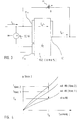
- FIG. 3 shows the basic structure of the amperometric measuring arrangement used.
- a voltage U is applied between the measuring electrode 11b and the counter electrode 40, and the current I flowing through the measuring electrode 11b, the solid electrolyte 6, preferably yttrium-stabilized zirconium dioxide (YSZ, 8 mol%) and the counter electrode 40 is measured.
- the voltage U is tracked in such a way that there is a constant potential difference U n between the measuring electrode 11b and reference electrode 11a.
- the solid electrolyte should be an oxygen anion conductor such as ZrO 2 or CeO 2 .
- a voltage source 31 is connected between the leads 25 of the electrodes 11b and 40, a current measuring device 20 between the lead to the measuring electrode 11b and the lead to the counter electrode 40 and a voltage measuring device 30 between the leads of the measuring 11b and reference electrode 11a.
- a curve of the current as a function of the voltage.
- the current thus varies between the value I 0 and I Conc . 2 .
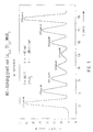
- FIG. 5 shows in a diagram the dependence of the current on the concentration of NO when measuring with an arrangement according to the invention with La 0.8 Sr 0.2 MnO 3 as the electrode material.
- the long-term stability of the measurement signal (I) at 0 and 2725 ppm NO concentration is readily apparent from the diagram according to FIG. 6.
Landscapes
- Chemical & Material Sciences (AREA)
- Life Sciences & Earth Sciences (AREA)
- Health & Medical Sciences (AREA)
- Physics & Mathematics (AREA)
- General Physics & Mathematics (AREA)
- Pathology (AREA)
- Immunology (AREA)
- Analytical Chemistry (AREA)
- Biochemistry (AREA)
- General Health & Medical Sciences (AREA)
- Engineering & Computer Science (AREA)
- Molecular Biology (AREA)
- Electrochemistry (AREA)
- Chemical Kinetics & Catalysis (AREA)
- Automation & Control Theory (AREA)
- Combustion & Propulsion (AREA)
- Food Science & Technology (AREA)
- Medicinal Chemistry (AREA)
- Measuring Oxygen Concentration In Cells (AREA)
Abstract
Description
- Die Erfindung betrifft eine Anordnung gemäß dem Oberbegriff des Hauptanspruchs.
- Eine solche Vorrichtung ist bekannt. (DE-U-91 03 547). Mit dieser bekannten Vorrichtung ist eine potentiometrische Messung der Konzentration von Stickoxiden, z.B. NO dadurch möglich, daß ohne Stromfluß durch die beiden elektrochemischen Halbzellen die sich von selbst einstellende Potentialdifferenz zwischen einer der Elektroden und der Gegenelektrode gemessen wird.
- Der Erfindung liegt demgegenüber die Aufgabe zugrunde, eine gattungsgemäße Anordnung gemäß dem Oberbegriff des Hauptanspruchs so weiter auszugestalten, daß eine Messung von NO mit deutlich verbesserter Empfindlichkeit möglich wird.
- Diese Aufgabe wird bei einer Anordnung gemäß dem Oberbegriff des Hauptanspruchs erfindungsgemäß durch dessen kennzeichnende Merkmale gelöst.
- Erfindungsgemäß wird hierbei zwischen der Meßelektrode und der Gegenelektrode eine variable Spannungsquelle geschaltet, wodurch sich ein aus der Gegenelektrode austretender elektrischer Strom ergibt, der eine Funktion der Konzentration von NO im Meßgas darstellt. Die angelegte Spannung wird dabei so nachgeführt, daß sich ein konstantes Potential an der Meß- und der Referenzelektrode ergibt. Die gemessene Stromstärke ist durch die Kinetik der ablaufenden Elektrodenreaktionen begrenzt, welche durch die Anwesenheit von NO verändert wird. Deshalb erweist sich als wichtige Grundlage der Auswahl des Elektrodenmaterials die katalytische Wirkung dieses Materials auf NO. Als Elektrodenmaterialien kommen hier perowskitische Verbindungen der Formel Ln1-xAMO3 in Frage, wobei hier Ln ein Element der Reihe Sc, Y, La oder ein Vertreter der Lanthaniden (Ordnungszahl 58-71), A zumindest ein Element der zweiten Hauptgruppe, M zumindest ein Element der Übergangsmetalle Cr, Mn, Fe, Co ist und x zwischen 0,01 und 0,5 liegt.
- Ferner lassen sich Querempfindlichkeiten, d.h. die Empfindlichkeit auf andere Gase im Gasgemisch durch Wahl des Materials der beiden Elektroden gezielt minimieren.
- Zweckmäßige Ausgestaltungen und Weiterbildungen der Erfindung sind in den abhängigen Ansprüchen gekennzeichnet.
- Ein bevorzugtes Ausführungsbeispiel wird nachfolgend unter Bezugnahme auf die Zeichnung näher erläutert. In dieser zeigt:
- Figur 1
- eine erste Ausführungsform der Anordnung, im schematischen Querschnitt;
- Figur 2
- die Anordnung gemäß Fig. 1, in Draufsicht;
- Figur 3
- den prinzipiellen Aufbau der Anordnung;
- Figur 4
- eine Kennlinienschar des zwischen Meß- und Gegenelektrode fließenden Stromes über der angelegten Spannung U mit der Konzentration an NO als Parameter;
- Figur 5
- ein Diagramm des fließenden Stromes in Abhängigkeit von NO; und
- Figur 6
- ein Diagramm über einen Langzeittest.
- Der Träger 41 für die elektrochemische Zelle, vorzugsweise aus Al2O3 weist auf dessen einer Seite 7 die Gegenelektrode 40, darüber eine poröse Schicht eines anionenleitenden Festelektrolyten (6), vorzugsweise yttriumdotiertes Zirkondioxid (8 Mol-%) und darüber die Referenz- 11a und Meßelektrode 11b auf, die nachfolgend noch näher erläutert werden. Bei dieser Anordnung muß die Meßelektrode 11b in Draufsicht die Gegenelektrode 40 gänzlich überdecken. Ferner ist auf der einen Seite 7 des als keramisches Plättchen ausgebildeten Trägers 41 ein die elektrochemische Zelle umschließender Temperaturfühler 8 vorgesehen. Auf der Rückseite 9 des Trägers 41 ist eine Widerstandsheizschicht 10 vorgesehen, die in Draufsicht mäanderförmig aufgebracht sein kann.
- Auf der Oberseite der als Festelektrolyt 6 dienenden dünnen Schicht sind zwei verschiedene Elektroden, nämlich eine Referenzelektrode 11a und eine Meßelektrode 11b, die vorzugsweise perowskitische Materialien der Summenformel Ln1-xAxMO3 (x = 0,01 bis 0,5) aufweisen, in Form dünner Schichten aufgebracht, die jeweils voneinander beabstandet angeordnet sind.
- Diese mittels Siebdrucktechnik und anschließendem Sintern hergestellte Anordnung in Planar- bzw. Dickschichttechnologie weist eine äußerst geringe Masse und kleine Einbaumaße auf und benötigt daher zur Aufnahme nur ein kleines Gehäuse.
- Zum Abgriff des Meßstromes sowie der Zuführung der Meßspannung sowie zur Beheizung der Widerstandsheizschicht 10 sind auf dem Träger 41 Metallschichten in Form von aufgedruckten Leiterbahnen 25 vorgesehen.
- In Fig. 3 ist der prinzipielle Aufbau der eingesetzten amperometrischen Meßanordnung dargestellt. Zwischen der Meßelektrode 11b und der Gegenelektrode 40 wird eine Spannung U angelegt, und der durch die Meßelektrode 11b, den Festelektrolyten 6, vorzugsweise yttriumstabilisiertes Zirkondioxid (YSZ, 8 Mol-%) und die Gegenelektrode 40 fließende Strom I gemessen. Dabei wird die Spannung U so nachgeführt, daß sich eine konstante Potentialdifferenz Un zwischen der Meßelektrode 11b und Referenzelektrode 11a ergibt. In jedem Falle sollte der Festelektrolyt ein Sauerstoffanionenleiter wie beispielsweise ZrO2 oder CeO2 sein.
- Demgemäß ist in Fig. 2 eine Spannungsquelle 31 zwischen die Zuleitungen 25 der Elektroden 11b und 40, ein Strommeßgerät 20 zwischen der Zuleitung zur Meßelektrode 11b und der Zuleitung zur Gegenelektrode 40 und ein Spannungsmeßgerät 30 zwischen die Zuleitungen der Meß- 11b und Referenzelektrode 11a geschaltet. Wie in Fig. 4 gezeigt, ergibt sich für jede Konzentration von NO eine Kurve des Stroms in Abhängigkeit der Spannung. Bei konstanter Spannung UK variiert somit der Strom zwischen dem Wert I0 und IKonz.2.
- Fig. 5 zeigt in einem Diagramm die Abhängigkeit des Stromes von der Konzentration von NO bei der Messung mit einer erfindungsgemäßen Anordnung mit La0,8Sr0,2MnO3 als Elektrodenmaterial. Die Langzeitstabilität des Meßsignals (I) bei 0 und 2725 ppm NO-Konzentration ergibt sich ohne weiteres aus dem Diagramm gemäß Fig. 6.
Claims (17)
- Anordnung zur kontinuierlichen Überwachung der Konzentration von Stickstoffoxid, vorzugsweise Stickstoffmonoxid (NO) in Gasgemischen mit einem Träger (41), der zumindest zwei elektrochemische Halbzellen mit einem sauerstoffionenleitenden Festelektrolyten (6) als dünne Schicht und mit einer porösen Festkörperstruktur versehene, vorzugsweise metall- und/oder metalloxidhaltige sowie mit den gasförmigen Bestandteilen wechselwirkende Elektroden (11a, 11b, 40) als dünne Schichten auf einer Seite (7) der beiden Seiten (7, 9) des Trägers aufweist, wobei ein von der Konzentration des NO abhängiges und in Konzentrationswerte umrechenbares elektrisches Meßsignal erzeugt wird, wobei auf der einen, nämlich der Oberseite (7) des Festelektrolyten zumindest zwei der Elektroden als Meßelektrode (11b) und Referenzelektrode (11a) zueinander beabstandet aufgebracht sind, und wobei unter dem Festelektrolyten (6) eine Gegenelektrode (40) auf dem Träger (41) angeordnet ist,
dadurch gekennzeichnet,
daß die Meßelektrode (11b) perowskitische Verbindungen aufweist, daß zwischen der Meßelektrode (11b) und der Gegenelektrode (40) eine Spannungsquelle (31) geschaltet ist und daß zwischen der Gegenelektrode (40) und der Meßelektrode (11b) ein Strommeßgerät (20) geschaltet ist, mit dem der aus der Gegenelektrode (40) austretende elektrische Strom (I) als Funktion der Konzentration von NO gemessen wird. - Anordnung nach Anspruch 1, dadurch gekennzeichnet, daß die Meßelektrode perowskitische Materialien der Formel Ln1-xAxMO3 aufweist, wobei Ln ein Element der Reihe Sc, Y, La oder ein Vertreter der Lanthaniden (Ordnungszahl 58-71), A zumindest ein Element der zweiten Hauptgruppe, M zumindest ein Element der Übergangsmetalle Cr, Mn, Fe, Co ist und x zwischen 0,01 und 0,5 liegt.
- Anordnung nach Anspruch 1 oder 2, dadurch gekennzeichnet, daß die angelegte Spannung (U) der Spannungsquelle (31) so nachgeführt wird, daß die Potentialdifferenz (Un) zwischen der Meßelektrode (11b) und der Referenzelektrode (11a) konstant gehalten wird.
- Anordnung nach Anspruch 1, 2 oder 3, dadurch gekennzeichnet, daß auf der anderen Seite (9) des Trägers (41) eine elektrische Widerstandsheizschicht (10) als Heizung vorgesehen ist.
- Anordnung nach Anspruch 1, 2 oder 3, dadurch gekennzeichnet, daß auf der einen Seite (7) des Trägers (41) ein von der Schicht des Festelektrolyten (6) und der Meß- (11b) und der Referenzelektrode (11a) beabstandeter Temperaturfühler (8) am Rand des Trägers (41) um die Elektroden (11a, 11b), die dünne Schicht des Festelektrolyten (6) und die Gegenelektrode (40), herumgeführt ist.
- Anordnung nach einem der Ansprüche 1 bis 5, dadurch gekennzeichnet, daß der Träger (41) als nicht-ionenleitende Keramik ausgebildet ist und auf der einen Seite (7) sowohl die Gegenelektrode (40) als auch den Temperaturfühler (8) sowie den Festelektrolyten (6) als dünne Schicht aufweist, auf dem die Elektroden (11a, 11b) aufgebracht sind.
- Anordnung nach Anspruch 6, dadurch gekennzeichnet, daß der Träger (41) Aluminiumoxid (Al2O3) aufweist.
- Anordnung nach einem der Ansprüche 5 bis 7, dadurch gekennzeichnet, daß der Träger (41) aus Keramik mit einem Anschlußstück für die elektrischen Zuleitungen (25) versehen ist.
- Anordnung nach einem der Ansprüche 1 bis 8, dadurch gekennzeichnet, daß der Festelektrolyt (6) ein Anionenleiter ist.
- Anordnung nach einem der Ansprüche 1 bis 8, dadurch gekennzeichnet, daß der Festelektrolyt (6) stabilisiertes ZrO2 oder CeO2 aufweist.
- Anordnung nach Anspruch 10, dadurch gekennzeichnet, daß der Festelektrolyt (6) yttriumdotiert ist.
- Anordnung nach Anspruch 11, dadurch gekennzeichnet, daß die Dotierung bevorzugt 8 Mol-% beträgt.
- Anordnung nach einem der Ansprüche 1 bis 9, dadurch gekennzeichnet, daß alle Schichten, nämlich die der Meß- (11b) und der Referenzelektroden (11a), die Gegenelektrode (40), die dünne Schicht des Festelektrolyten (6), der Temperaturfühler (8) und die Widerstandsheizschicht (10) in Dickschichttechnologie auf dem Träger (41) aufgebracht sind.
- Anordnung nach Anspruch 13, dadurch gekennzeichnet, daß die Schichten mittels Siebdruck aufgebracht sind.
- Anordnung nach den Ansprüchen 1 bis 14, dadurch gekennzeichnet, daß die Gegenelektrode (40) und/oder die Referenzelektrode (11a) eine perowskitische Verbindung aufweist.
- Anordnung nach einem der Ansprüche 1 bis 15, dadurch gekennzeichnet, daß die Gegenelektrode (40) und/oder die Referenzelektrode (11a) Ln1-xAxMO3 aufweist, wobei Ln ein Element der Reihe Sc, Y, La oder ein Vertreter der Lanthaniden (Ordnungszahl 58-71) und A zumindest ein Element der 2. Hauptgruppe und M zumindest ein Element der Übergangsmetalle Cr, Mn, Fe oder Co ist.
- Anordnung nach Anspruch 16, wobei x = 0,01 bis 0,5 ist.
Applications Claiming Priority (3)
| Application Number | Priority Date | Filing Date | Title |
|---|---|---|---|
| DE4225775A DE4225775C2 (de) | 1992-08-04 | 1992-08-04 | Anordnung zum kontinuierlichen Überwachen der Konzentration von NO in Gasgemischen |
| DE4225775 | 1992-08-04 | ||
| PCT/EP1993/002075 WO1994003796A1 (de) | 1992-08-04 | 1993-08-04 | Anordnung zum kontinuierlichen überwachen der konzentration von no in gasgemischen |
Publications (3)
| Publication Number | Publication Date |
|---|---|
| EP0606456A1 EP0606456A1 (de) | 1994-07-20 |
| EP0606456B1 true EP0606456B1 (de) | 1996-11-20 |
| EP0606456B2 EP0606456B2 (de) | 2000-10-18 |
Family
ID=6464826
Family Applications (1)
| Application Number | Title | Priority Date | Filing Date |
|---|---|---|---|
| EP93917741A Expired - Lifetime EP0606456B2 (de) | 1992-08-04 | 1993-08-04 | Anordnung zum kontinuierlichen überwachen der konzentration von no in gasgemischen |
Country Status (6)
| Country | Link |
|---|---|
| EP (1) | EP0606456B2 (de) |
| JP (1) | JP3109833B2 (de) |
| KR (1) | KR100275306B1 (de) |
| DE (2) | DE4225775C2 (de) |
| ES (1) | ES2098050T3 (de) |
| WO (2) | WO1994003795A1 (de) |
Families Citing this family (11)
| Publication number | Priority date | Publication date | Assignee | Title |
|---|---|---|---|---|
| JP3524980B2 (ja) * | 1995-03-10 | 2004-05-10 | 株式会社リケン | 窒素酸化物センサ |
| EP0763789B1 (de) * | 1995-09-18 | 1999-11-03 | Werner Göhring | Verfahren und Vorrichtung zur Messung und Regelung einer Aufkohlungs- und/oder Nitrieratmosphäre |
| US5933160A (en) | 1995-11-27 | 1999-08-03 | Sun Microsystems | High-performance band combine function |
| WO1997042495A1 (en) * | 1996-05-07 | 1997-11-13 | Sri International | Solid state electrochemical cell for measuring components of a gas mixture, and related measurement method |
| DE19623212A1 (de) * | 1996-06-11 | 1997-12-18 | Bosch Gmbh Robert | Sensor zur Bestimmung der Konzentration oxidierbarer Bestandteile in einem Gasgemisch |
| WO1999014584A1 (de) | 1997-09-15 | 1999-03-25 | Heraeus Electro-Nite International N.V. | Gassensor |
| DE19757112C2 (de) | 1997-09-15 | 2001-01-11 | Heraeus Electro Nite Int | Gassensor |
| DE10048031B4 (de) * | 2000-09-26 | 2004-04-29 | Epiq Sensor-Nite N.V. | Verfahren zur Bestimmung des NOx-Gehaltes eines Messgases |
| JP3966805B2 (ja) * | 2002-11-18 | 2007-08-29 | 株式会社日立製作所 | 空燃比検出装置 |
| KR100531376B1 (ko) * | 2003-06-16 | 2005-11-28 | 엘지전자 주식회사 | 이산화탄소 가스 센서 및 그 제조방법 |
| JP2010261855A (ja) * | 2009-05-08 | 2010-11-18 | Japan Fine Ceramics Center | 窒素酸化物センサ及び窒素酸化物の検出方法 |
Family Cites Families (13)
| Publication number | Priority date | Publication date | Assignee | Title |
|---|---|---|---|---|
| US3902970A (en) * | 1973-07-30 | 1975-09-02 | Leeds & Northrup Co | Flow-through amperometric measuring system and method |
| DE2631819A1 (de) * | 1976-07-15 | 1978-01-19 | Bbc Brown Boveri & Cie | Verfahren und vorrichtung zum bestimmen des gehaltes an molekularem und/oder gebundenem sauerstoff in gasen |
| US4088543A (en) * | 1976-09-10 | 1978-05-09 | Westinghouse Electric Corp. | Technique for protecting sensing electrodes in sulfiding environments |
| DE2965652D1 (en) * | 1978-06-12 | 1983-07-21 | Corning Glass Works | Hot gas measuring device |
| DE2949871A1 (de) * | 1979-12-12 | 1981-06-25 | Drägerwerk AG, 2400 Lübeck | Vorrichtung zur analyse von gasgemischen mit oxidierbaren gemischanteilen |
| DE3010632A1 (de) * | 1980-03-20 | 1981-10-01 | Bosch Gmbh Robert | Polarographischer messfuehler fuer die bestimmung des sauerstoffgehalts in gasen |
| DE3112739A1 (de) † | 1981-03-31 | 1982-10-07 | Bosch Gmbh Robert | "strukturstabile elektrode fuer festelektrolyte fuer elektrochemische anwendungen sowie verwendung einer solchen elektrode in elektrochemischen messfuehlern zur bestimmung des sauerstoffgehaltes in gasen" |
| DE3315654A1 (de) * | 1983-04-29 | 1984-10-31 | Bosch Gmbh Robert | Polarographischer messfuehler fuer die bestimmung des sauerstoff-gehaltes in gasen |
| DE3610363A1 (de) * | 1986-03-27 | 1987-10-01 | Kernforschungsz Karlsruhe | Verfahren zum kontinuierlichen ueberwachen von konzentrationen von gasfoermigen bestandteilen in gasgemischen, ausgenommen o(pfeil abwaerts)2(pfeil abwaerts) |
| JPH0672861B2 (ja) * | 1986-08-04 | 1994-09-14 | 日本碍子株式会社 | NOxセンサ |
| JP2636883B2 (ja) * | 1988-04-30 | 1997-07-30 | 日本碍子株式会社 | NOx濃度測定装置 |
| US5034107A (en) * | 1989-12-12 | 1991-07-23 | Gte Laboratories Incorporated | Method for sensing nitrous oxide |
| DE4109516C2 (de) * | 1991-01-30 | 1997-08-07 | Roth Technik Gmbh | Vorrichtung zum kontinuierlichen Überwachen der Konzentrationen von gasförmigen Bestandteilen in Gasgemischen |
-
1992
- 1992-08-04 DE DE4225775A patent/DE4225775C2/de not_active Expired - Fee Related
-
1993
- 1993-06-05 WO PCT/EP1993/001426 patent/WO1994003795A1/de not_active Ceased
- 1993-08-04 EP EP93917741A patent/EP0606456B2/de not_active Expired - Lifetime
- 1993-08-04 DE DE59304540T patent/DE59304540D1/de not_active Expired - Fee Related
- 1993-08-04 WO PCT/EP1993/002075 patent/WO1994003796A1/de not_active Ceased
- 1993-08-04 ES ES93917741T patent/ES2098050T3/es not_active Expired - Lifetime
- 1993-08-04 KR KR1019940701088A patent/KR100275306B1/ko not_active Expired - Fee Related
- 1993-08-04 JP JP06505016A patent/JP3109833B2/ja not_active Expired - Fee Related
Also Published As
| Publication number | Publication date |
|---|---|
| ES2098050T3 (es) | 1997-04-16 |
| DE4225775C2 (de) | 2002-09-19 |
| WO1994003796A1 (de) | 1994-02-17 |
| DE59304540D1 (de) | 1997-01-02 |
| JP3109833B2 (ja) | 2000-11-20 |
| JPH06511560A (ja) | 1994-12-22 |
| KR100275306B1 (ko) | 2000-12-15 |
| WO1994003795A1 (de) | 1994-02-17 |
| EP0606456A1 (de) | 1994-07-20 |
| EP0606456B2 (de) | 2000-10-18 |
| DE4225775A1 (de) | 1994-02-10 |
Similar Documents
| Publication | Publication Date | Title |
|---|---|---|
| DE69030098T2 (de) | Gassensor mit festem Elektrolyt und Verfahren zum Messen der Konzentration des zu detektierenden Gases in einer Gasmischung | |
| DE19827927C2 (de) | Gassensor | |
| DE19912102C2 (de) | Elektrochemischer Gassensor | |
| EP0606456B2 (de) | Anordnung zum kontinuierlichen überwachen der konzentration von no in gasgemischen | |
| WO1991006001A1 (de) | Gas-sensor-anordnung | |
| EP0938668A1 (de) | Gassensor | |
| DE69930175T2 (de) | Kohlenwasserstoffsensor | |
| DE2513264A1 (de) | Verfahren und vorrichtung zum auffinden und messen von stickoxid und stickstoffdioxid in gasen | |
| EP1240506B1 (de) | Gassensor zur bestimmung der konzentration von gaskomponenten in gasgemischen und dessen verwendung | |
| DE69730810T2 (de) | Gas Sensor | |
| DE19734861C2 (de) | Sensorelement zur Bestimmung der Konzentration oxidierbarer Bestandteile in einem Gasgemisch | |
| DE19757112C2 (de) | Gassensor | |
| EP0795127A1 (de) | Vorrichtung und verfahren zur bestimmung von gasförmigen bestandteilen in gasgemischen | |
| DE102009031773B4 (de) | Potentiometrischer Sensor zur kombinierten Bestimmung der Konzentration eines ersten und eines zweiten Gasbestandteils einer Gasprobe, insbesondere zur kombinierten Bestimmung von CO2 und O2, entsprechendes Bestimmungsverfahren und Verwendung derselben | |
| EP1023591B1 (de) | AUFBAUSTRUKTUR FÜR NO x?-SENSOREN | |
| DE3606044A1 (de) | Luft/kraftstoff-verhaeltnissensor | |
| EP0867714B1 (de) | Elektrodenmaterial | |
| EP1217361A2 (de) | Mehrstufiger Gassensor, Betriebs- und Herstellungsverfahren | |
| DE19503783C2 (de) | CO¶2¶ - Sensor | |
| EP0522118A1 (de) | Vorrichtung zum kontinuierlichen überwachen der konzentrationen von gasförmigen bestandteilen in gasgemischen. | |
| DE2817873A1 (de) | Detektoreinrichtung zur erfassung von gaskomponenten | |
| DE4243734C2 (de) | Sensor zur Bestimmung von Gaskomponenten und/oder von Gaskonzentrationen von Gasgemischen | |
| DD147285A5 (de) | Elektrochemischer messfuehler | |
| EP0420107B2 (de) | Feststoff-Sauerstoffsensor | |
| DE10319878A1 (de) | Potentiometrischer Kohlenwasserstoffsensor mit sauerstoffpartialdruckunabhängiger Kennlinie |
Legal Events
| Date | Code | Title | Description |
|---|---|---|---|
| PUAI | Public reference made under article 153(3) epc to a published international application that has entered the european phase |
Free format text: ORIGINAL CODE: 0009012 |
|
| 17P | Request for examination filed |
Effective date: 19940331 |
|
| AK | Designated contracting states |
Kind code of ref document: A1 Designated state(s): DE ES FR GB IT NL SE |
|
| RBV | Designated contracting states (corrected) |
Designated state(s): DE ES FR GB IT NL SE |
|
| 17Q | First examination report despatched |
Effective date: 19950920 |
|
| GRAG | Despatch of communication of intention to grant |
Free format text: ORIGINAL CODE: EPIDOS AGRA |
|
| GRAH | Despatch of communication of intention to grant a patent |
Free format text: ORIGINAL CODE: EPIDOS IGRA |
|
| GRAH | Despatch of communication of intention to grant a patent |
Free format text: ORIGINAL CODE: EPIDOS IGRA |
|
| GRAA | (expected) grant |
Free format text: ORIGINAL CODE: 0009210 |
|
| AK | Designated contracting states |
Kind code of ref document: B1 Designated state(s): DE ES FR GB IT NL SE |
|
| PG25 | Lapsed in a contracting state [announced via postgrant information from national office to epo] |
Ref country code: NL Free format text: LAPSE BECAUSE OF FAILURE TO SUBMIT A TRANSLATION OF THE DESCRIPTION OR TO PAY THE FEE WITHIN THE PRESCRIBED TIME-LIMIT Effective date: 19961120 |
|
| RAP1 | Party data changed (applicant data changed or rights of an application transferred) |
Owner name: ROTH-TECHNIK GMBH & CO. FORSCHUNG FUER AUTOMOBIL- |
|
| REF | Corresponds to: |
Ref document number: 59304540 Country of ref document: DE Date of ref document: 19970102 |
|
| ITF | It: translation for a ep patent filed | ||
| ET | Fr: translation filed | ||
| GBT | Gb: translation of ep patent filed (gb section 77(6)(a)/1977) |
Effective date: 19970219 |
|
| REG | Reference to a national code |
Ref country code: ES Ref legal event code: FG2A Ref document number: 2098050 Country of ref document: ES Kind code of ref document: T3 |
|
| NLV1 | Nl: lapsed or annulled due to failure to fulfill the requirements of art. 29p and 29m of the patents act | ||
| PGFP | Annual fee paid to national office [announced via postgrant information from national office to epo] |
Ref country code: GB Payment date: 19970716 Year of fee payment: 5 |
|
| PGFP | Annual fee paid to national office [announced via postgrant information from national office to epo] |
Ref country code: SE Payment date: 19970724 Year of fee payment: 5 |
|
| PGFP | Annual fee paid to national office [announced via postgrant information from national office to epo] |
Ref country code: ES Payment date: 19970829 Year of fee payment: 5 |
|
| PLBI | Opposition filed |
Free format text: ORIGINAL CODE: 0009260 |
|
| PLBF | Reply of patent proprietor to notice(s) of opposition |
Free format text: ORIGINAL CODE: EPIDOS OBSO |
|
| RAP2 | Party data changed (patent owner data changed or rights of a patent transferred) |
Owner name: HERAEUS ELECTRO-NITE INTERNATIONAL N.V. |
|
| 26 | Opposition filed |
Opponent name: ROBERT BOSCH GMBH Effective date: 19970819 |
|
| REG | Reference to a national code |
Ref country code: GB Ref legal event code: 732E |
|
| PLBF | Reply of patent proprietor to notice(s) of opposition |
Free format text: ORIGINAL CODE: EPIDOS OBSO |
|
| PG25 | Lapsed in a contracting state [announced via postgrant information from national office to epo] |
Ref country code: GB Free format text: LAPSE BECAUSE OF NON-PAYMENT OF DUE FEES Effective date: 19980804 |
|
| PG25 | Lapsed in a contracting state [announced via postgrant information from national office to epo] |
Ref country code: SE Free format text: LAPSE BECAUSE OF NON-PAYMENT OF DUE FEES Effective date: 19980805 Ref country code: ES Free format text: THE PATENT HAS BEEN ANNULLED BY A DECISION OF A NATIONAL AUTHORITY Effective date: 19980805 |
|
| GBPC | Gb: european patent ceased through non-payment of renewal fee |
Effective date: 19980804 |
|
| EUG | Se: european patent has lapsed |
Ref document number: 93917741.6 |
|
| PLAW | Interlocutory decision in opposition |
Free format text: ORIGINAL CODE: EPIDOS IDOP |
|
| PLAW | Interlocutory decision in opposition |
Free format text: ORIGINAL CODE: EPIDOS IDOP |
|
| PUAH | Patent maintained in amended form |
Free format text: ORIGINAL CODE: 0009272 |
|
| STAA | Information on the status of an ep patent application or granted ep patent |
Free format text: STATUS: PATENT MAINTAINED AS AMENDED |
|
| 27A | Patent maintained in amended form |
Effective date: 20001018 |
|
| AK | Designated contracting states |
Kind code of ref document: B2 Designated state(s): DE ES FR GB IT NL SE |
|
| REG | Reference to a national code |
Ref country code: ES Ref legal event code: FD2A Effective date: 20001204 |
|
| ET3 | Fr: translation filed ** decision concerning opposition | ||
| ITF | It: translation for a ep patent filed | ||
| REG | Reference to a national code |
Ref country code: FR Ref legal event code: TP |
|
| PGFP | Annual fee paid to national office [announced via postgrant information from national office to epo] |
Ref country code: FR Payment date: 20020812 Year of fee payment: 10 |
|
| PG25 | Lapsed in a contracting state [announced via postgrant information from national office to epo] |
Ref country code: FR Free format text: LAPSE BECAUSE OF NON-PAYMENT OF DUE FEES Effective date: 20040430 |
|
| REG | Reference to a national code |
Ref country code: FR Ref legal event code: ST |
|
| PG25 | Lapsed in a contracting state [announced via postgrant information from national office to epo] |
Ref country code: IT Free format text: LAPSE BECAUSE OF NON-PAYMENT OF DUE FEES;WARNING: LAPSES OF ITALIAN PATENTS WITH EFFECTIVE DATE BEFORE 2007 MAY HAVE OCCURRED AT ANY TIME BEFORE 2007. THE CORRECT EFFECTIVE DATE MAY BE DIFFERENT FROM THE ONE RECORDED. Effective date: 20050804 |
|
| PGFP | Annual fee paid to national office [announced via postgrant information from national office to epo] |
Ref country code: DE Payment date: 20050824 Year of fee payment: 13 |
|
| PG25 | Lapsed in a contracting state [announced via postgrant information from national office to epo] |
Ref country code: DE Free format text: LAPSE BECAUSE OF NON-PAYMENT OF DUE FEES Effective date: 20070301 |