EP0601469B1 - Büchsenförderkette - Google Patents
Büchsenförderkette Download PDFInfo
- Publication number
- EP0601469B1 EP0601469B1 EP93119397A EP93119397A EP0601469B1 EP 0601469 B1 EP0601469 B1 EP 0601469B1 EP 93119397 A EP93119397 A EP 93119397A EP 93119397 A EP93119397 A EP 93119397A EP 0601469 B1 EP0601469 B1 EP 0601469B1
- Authority
- EP
- European Patent Office
- Prior art keywords
- bush
- lubrication
- roller
- cover
- pin
- Prior art date
- Legal status (The legal status is an assumption and is not a legal conclusion. Google has not performed a legal analysis and makes no representation as to the accuracy of the status listed.)
- Expired - Lifetime
Links
Images

Classifications
-
- B—PERFORMING OPERATIONS; TRANSPORTING
- B65—CONVEYING; PACKING; STORING; HANDLING THIN OR FILAMENTARY MATERIAL
- B65G—TRANSPORT OR STORAGE DEVICES, e.g. CONVEYORS FOR LOADING OR TIPPING, SHOP CONVEYOR SYSTEMS OR PNEUMATIC TUBE CONVEYORS
- B65G45/00—Lubricating, cleaning, or clearing devices
- B65G45/02—Lubricating devices
- B65G45/08—Lubricating devices for chains
-
- F—MECHANICAL ENGINEERING; LIGHTING; HEATING; WEAPONS; BLASTING
- F16—ENGINEERING ELEMENTS AND UNITS; GENERAL MEASURES FOR PRODUCING AND MAINTAINING EFFECTIVE FUNCTIONING OF MACHINES OR INSTALLATIONS; THERMAL INSULATION IN GENERAL
- F16G—BELTS, CABLES, OR ROPES, PREDOMINANTLY USED FOR DRIVING PURPOSES; CHAINS; FITTINGS PREDOMINANTLY USED THEREFOR
- F16G13/00—Chains
- F16G13/02—Driving-chains
- F16G13/06—Driving-chains with links connected by parallel driving-pins with or without rollers so-called open links
Definitions
- the invention relates to a bush conveyor chain with the features according to the preamble of claim 1 (see e.g. FR-A-2 519 324).
- bush conveyor chains of this type depends on the fact that lubricant is constantly present at the joint between the bush and roller on the one hand and between bush and bolt on the other hand. Since with the prior art rifle conveyor chains losses of lubricant must be expected during operation, this requires continuous lubrication and associated costs for maintenance and problems with the disposal of the lubricants.
- the object of the invention is to be seen in designing a sleeve conveyor chain in such a way that the outlay for maintenance is considerably reduced compared to the prior art.
- the claim 2 has the application of this solution to another hinge point of the bush conveyor chain to the content.
- special sealing elements are installed, which seal the side of each chain roller, the spaces filled with lubricant.
- the cylindrical lubricant spaces are continued on each side of the roller by flat lubricant spaces, so that the lubricant can also reach the end faces of the roller.
- These lateral lubricant spaces are delimited on each side by the flat leg of a cover firmly pressed onto the bush. This rests elastically on a lip of a sealing ring inserted under pretension in a groove in the roller, so that a seal is thereby created even with tolerances that prevent the escape of lubricant prevented.
- a cylindrical leg of the lid mechanically protects the elastic sealing ring and prevents dirt from entering.
- the sealing concept according to the invention thus represents a combination of a labyrinth seal and a sliding seal, i.e. two sealing systems are used together in the form of a double seal. It reliably prevents the penetration of foreign particles and moisture, as well as the escape of primary lubricant from the joints, although relubrication of the joints is still possible via a grease nipple in the chain pin. A necessary radial and axial play of the chain is compensated for without reducing the sealing effect.
- the sealing ring with lip is made of a fully elastic material. A material with a high surface quality in the sealing area is used for the cover. During assembly, the cover is pressed together with the link plate onto the bolt or sleeve. The wrench flats on the bolt and bush provide the necessary anti-twist protection for the cover.
- the invention further relates to a sealing of the lubricant spaces on the joint surfaces between the pin and the bush. Together with the measures according to claim 1, there is universal protection of the chain links.
- a shoulder is provided at the end region of the bushing or in the groove, the length of which is chosen so that the sealing ring is not destroyed.
- the axial play of the roller, bush and pin is chosen so that the preload of the seal is not exceeded.
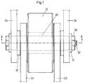
- the sleeve conveyor chain consists of rollers 10 arranged in a row, each rotatably supported on a sleeve 20. This sleeve rotatably receives a pin 30.
- an inner tab 23 is mounted, firmly pressed onto the sleeve 20. The inner tabs 23 connect two rollers to form a pair of rollers (inner link).
- An outer tab 24 is also arranged on each side, firmly pressed onto the bolt.
- Two outer brackets 24 each articulate connect two pairs of rollers (outer link). Between each inner tab 23 and an outer tab 24, a cover 37 is inserted, which protects the elements which are provided for sealing the spaces filled with grease or oil. Channels are also provided in the bolt for the supply of lubricant. The lubricant is supplied via a grease nipple 32. The axial position of the articulated brackets is secured by means of locking rings 31 attached to the bolt.
- FIG. 2 Here you can see the axial lubricant channel 33 in the bolt 30 from which radial lubricant channels 34 extend, which lead to the lubricant chamber 35. This is filled with lubricant for the lubrication of the cylindrical lubricating surface 36 between the pin and the bushing 20. The lubricant can also get into a cylindrical lubricant chamber 11, which is formed in the roller 10, via radial channels in the bushing 20. The lubricant in space 11 as a lubricant reserve serves to lubricate the cylindrical lubricating surface 12 between the bush and the roller.
- This cylindrical lubricant surface 12 is continued on each side of the roller by a lateral, that is to say flat, lubricating surface 13.
- the relevant lubricant space is delimited on each side by a cover 14 which is pressed firmly onto the bushing 20 and which has a cylindrical leg 14b into one circumferential groove 15 protrudes into the roller 10.
- An elastic sealing ring 16 with a square or rectangular cross section is inserted into the groove 22 on the shoulder 22 under prestress.
- a lip 16a is integrally formed on this sealing ring in such a way that it rests permanently elastically on the flat leg 14a of the cover 14. As a result, the space filled with lubricant between the roller 10 and the flat leg 14a of the cover 14 is blocked off.
- the sealing ring 16 is protected from dirt or damage by the cylindrical leg 14b of the cover.
- a lubricant space 35 is also formed on the pin, from which the lubricant can get into the cylindrical lubricating surface 36.
- the lubricant can also reach the end face of the bush 20, where a lateral lubricant space 36a is formed, on the one hand limited through the end face of the sleeve 20 and through the flat leg 37a of a cover 37 which is pressed firmly onto the bolt.
- FIG. 3 shows the sealing area III according to FIG. 2 on an enlarged scale. It can be seen from FIG. 3 that the sealing lip 38a also rests elastically and exerts its locking action when a maximum play has occurred between the cover and the bush in the axial direction. The sealing effect is not impaired even by play in the radial direction.
- Fig. 4 shows the position of the sealing elements with minimal play between the sleeve and cover.
Landscapes
- Engineering & Computer Science (AREA)
- Mechanical Engineering (AREA)
- General Engineering & Computer Science (AREA)
- Sealing Devices (AREA)
- Devices For Conveying Motion By Means Of Endless Flexible Members (AREA)
- Chain Conveyers (AREA)
- Pusher Or Impeller Conveyors (AREA)
- Attitude Control For Articles On Conveyors (AREA)
- General Details Of Gearings (AREA)
- Sealing Of Bearings (AREA)
- Rolling Contact Bearings (AREA)
Description
- Die Erfindung bezieht sich auf eine Büchsenförderkette mit den Merkmalen nach dem Oberbegriff des Anspruchs 1 (siehe z.B. FR-A-2 519 324).
- Der einwandfreie Betrieb von Büchsenförderketten dieser Art hängt davon ab, daß an der Gelenkstelle einerseits zwischen Büchse und Rolle und andererseits zwischen Büchse und Bolzen ständig Schmiermittel vorhanden ist. Da bei den Büchsenförderketten nach dem Stand der Technik während des Betriebs mit Verlusten an Schmiermittel gerechnet werden muß, erfordert dies eine fortlaufende Betriebsschmierung und damit verbunden Kosten für die Wartung, sowie Probleme bei der Entsorgung der Schmiermittel.
- Die Aufgabe der Erfindung ist darin zu sehen, eine Büchsenförderkette so auszubilden, daß der Aufwand für die Wartung gegenüber dem Stand der Technik erheblich vermindert wird.
- Diese Aufgabe wird durch die Merkmale nach dem Anspruch 1 gelöst. Der Anspruch 2 hat die Anwendung dieser Lösung an einer anderen Gelenkstelle der Büchsenförderkette zum Inhalt.
- Nach der Lösung des Anspruchs 1 sind spezielle Dichtungselemente eingebaut, welche seitlich einer jeden Kettenrolle, die mit Schmiermittel gefüllten Räume abdichten. Die zylindrischen Schmiermittelräume werden an jeder Seite der Rolle fortgesetzt durch ebene Schmiermittelräume, so daß das Schmiermittel auch an die Stirnseiten der Rolle gelangen kann. Diese seitlichen Schmiermittelräume sind an jeder Seite begrenzt durch den ebenen Schenkel eines auf die Büchse fest aufgepreßten Deckels. Daran liegt elastisch eine Lippe eines unter Vorspannung in eine Nut der Rolle eingesetzten Dichtungsrings, so daß dadurch auch bei Toleranzen eine Abdichtung bewirkt wird, die das Austreten von Schmiermittel verhindert. Ein zylindrischer Schenkel des Deckels schützt dabei mechanisch den elastischen Dichtungsring und verhindert das Eindringen von Schmutz.
- Das Dichtungskonzept nach der Erfindung stellt somit eine Kombination einer Labyrinthdichtung und einer schleifenden Dichtung dar, d.h. zwei Dichtungssysteme werden vereint eingesetzt in Form einer Doppeldichtung. Sie verhindert zuverlässig das Eindringen von Fremdpartikeln und Feuchtigkeit, sowie das Austreten von Erstschmiermittel aus den Gelenken, wobei trotzdem eine Nachschmierung der Gelenke über einen Schmiernippel im Kettenbolzen möglich ist. Ein notwendiges radiales sowie axiales Spiel der Kette wird ohne Minderung der Dichtwirkung ausgeglichen. Der Dichtungsring mit Lippe besteht aus einem vollelastischen Werkstoff. Für den Deckel verwendet man einen Werkstoff mit hoher Oberflächengüte im Dichtungsbereich. Der Deckel wird bei der Montage zusammen mit der Kettenlasche auf den Bolzen bzw. auf die Büchse gepreßt. Die Schlüsselflächen auf Bolzen und Büchse ergeben dabei die nötige Verdrehungssicherung des Deckels.
- Die Erfindung bezieht sich weiter auf eine Abdichtung der Schmiermittelräume an den Gelenkflächen zwischen Bolzen und Büchse. Zusammen mit den Maßnahmen nach Anspruch 1 entsteht ein universeller Schutz der Kettengelenke. Zur Aufnahme des elastischen Dichtungsringes für die Abdichtung zwischen Büchse und Bolzen sowie Rolle und Büchse ist am Endbereich der Büchse bzw. in der Nut ein Absatz vorgesehen, dessen Länge so gewählt ist, daß der Dichtungsring nicht zerstört wird. Das axiale Spiel von Rolle, Büchse und Bolzen ist so gewählt, daß der Vorspannweg der Dichtung nicht überschritten wird.
- Im folgenden wird ein Ausführungsbeispiel der Erfindung beschrieben unter Bezugnahme auf die beiliegenden Zeichnungen.
- Fig. 1
- zeigt eine Draufsicht auf eine Büchsenförderkette nach der Erfindung im Bereich eines Kettengelenkes;
- Fig. 2
- ist ein Schnitt nach II-II von Fig. 1;
- Fig. 3 und 4
- stellen die Abdichtungselemente nach III von Fig. 2 in unterschiedlichen Positionen dar.
- Zunächst wird auf Fig. 1 Bezug genommen. Die Büchsenförderkette besteht aus in Reihe angeordneten Rollen 10, jede drehbar gelagert auf einer Büchse 20. Diese nimmt drehbar einen Bolzen 30 auf. An jeder Seite der Rolle 10 ist eine innere Lasche 23 gelagert, fest auf die Büchse 20 aufgepreßt. Die inneren Laschen 23 verbinden zwei Rollen zu einem Rollenpaar (Innenglied).
- An jeder Seite ist außerdem eine äußere Lasche 24 angeordnet, fest auf dem Bolzen aufgepreßt. Zwei äußere Laschen 24 verbinden jeweils gelenkig zwei Rollenpaare (Außenglied). Zwischen jeder inneren Lasche 23 und einer äußeren Lasche 24 ist ein Deckel 37 eingesetzt, der die Elemente schützt, welche zur Abdichtung der mit Fett oder Öl gefüllten Räume vorgesehen sind. Für die Zuführung von Schmiermittel sind überdies im Bolzen Kanäle vorgesehen. Die Zuführung des Schmiermittels erfolgt über einen Schmiernippel 32. Durch auf den Bolzen aufgesteckte Sicherungsringe 31 ist die axiale Position der Gelenklaschen gesichert.
- Im folgenden wird auf Fig. 2 Bezug genommen. Hier erkennt man den axialen Schmiermittelkanal 33 im Bolzen 30 von dem radiale Schmiermittelkanäle 34 abgehen, welche zum Schmiermittelraum 35 führen. Dieser ist mit Schmiermittel gefüllt zur Schmierung der zylindrischen Schmierfläche 36 zwischen Bolzen und Büchse 20. Das Schmiermittel kann außerdem über radiale Kanäle in der Büchse 20 in einen zylindrischen Schmiermittelraum 11, der in der Rolle 10 gebildet ist, gelangen. Das Schmiermittel im Raum 11 als Schmiermittelreserve dient zur Schmierung der zylindrischen Schmierfläche 12 zwischen Büchse und Rolle.
- Diese zylindrische Schmiermittelfläche 12 ist an jeder Seite der Rolle fortgesetzt durch eine seitliche, also ebene Schmierfläche 13. Der diesbezügliche Schmiermittelraum ist begrenzt an jeder Seite durch einen Deckel 14, der fest auf die Büchse 20 aufgepreßt ist und der mit einem zylindrischen Schenkel 14b in eine umlaufende Nut 15 in der Rolle 10 hineinragt. In diese Nut ist auf dem Ansatz 22 unter Vorspannung ein elastischer Dichtungsring 16 mit quadratischem oder rechteckigem Querschnitt eingesetzt. An diesem Dichtungsring ist eine Lippe 16a angeformt derart, daß sie ständig elastisch am ebenen Schenkel 14a des Deckels 14 anliegt. Dadurch ist der mit Schmiermittel gefüllte Raum zwischen Rolle 10 und dem ebenen Schenkel 14a des Deckels 14 abgesperrt. Durch den zylindrischen Schenkel 14b des Deckels ist der Dichtungsring 16 vor Verschmutzung oder Beschädigung geschützt.
- Um den Vorrat des Schmiermittels, das zur Schmierung zwischen Bolzen und Büchse dient, zu vergrößern, ist gleichfalls am Bolzen ein Schmiermittelraum 35 gebildet von dem aus das Schmiermittel in die zylindrische Schmierfläche 36 gelangen kann. Das Schmiermittel kann aber auch an die Stirnseite der Büchse 20 gelangen, wo ein seitlicher Schmiermittelraum 36a gebildet ist, begrenzt einerseits durch die Stirnfläche der Büchse 20 und durch den ebenen Schenkel 37a eines Deckels 37, der fest auf den Bolzen aufgepreßt ist. Auf einem Absatz der Büchse ist unter Vorspannung auch hier ein elastischer Dichtungsring 38 aufgebracht mit einer Lippe 38a, die zur Absperrung des Schmiermittelraumes 36a elastisch am Deckel 37 anliegt.
- Fig. 3 stellt in vergrößertem Maßstab den Dichtungsbereich III nach Fig. 2 dar. Man erkennt aus Fig. 3, daß die Dichtungslippe 38a auch dann elastisch anliegt und ihre Sperrwirkung ausübt, wenn zwischen Deckel und Büchse in axialer Richtung ein maximales Spiel entstanden ist. Auch durch ein Spiel in radialer Richtung wird die Dichtwirkung nicht beeinträchtigt.
- Fig. 4 zeigt die Stellung der Dichtungselemente bei minimalen Spiel zwischen Büchse und Deckel.
Claims (4)
- Büchsenförderkette mit den Merkmalen:- sie hat in Reihe hintereinander angeordnete Rollen (10), die drehbar auf einer Büchse (20) gelagert sind, wobei diese drehbar auf einem Bolzen (30) gelagert ist;- an jeder Seite der Rolle ist eine innere Lasche (23) angeordnet, fest auf die Büchse aufgepreßt, wobei die beiden Laschen zwei Rollen zu einem Paar verbinden;- neben den inneren Laschen sind zwei äußere Laschen (24) angeordnet, fest auf den Bolzen gepreßt, die jeweils ein Rollenpaar gelenkig verbinden;- zwischen Rolle und Büchse einerseits und zwischen Büchse und Bolzen andererseits sind zylindrische Schmiermittelflächen bzw. Räume (11, 12, 35, 36) vorgesehen;gekennzeichnet durch die nachfolgend genannten Merkmale:- die zylindrischen Schmierflächen (12) zwischen Büchse (20) und Rolle (10) sind an jeder Seite durch eine seitliche Schmierfläche (13) fortgesetzt, begrenzt durch eine Stirnfläche der Rolle und durch einen ebenen Schenkel (14a) eines auf die Büchse fest aufgepreßten Deckels (14), dessen zylindrischer Schenkel (14b) in eine an der Rolle (10) gebildeten Nut (15) hineinragt;- ein Ansatz (22) in der Nut nimmt unter Vorspannung einen elastischen Dichtungsring (16) auf, mit einer am Deckel elastisch anliegenden Lippe (16a).
- Büchsenförderkette nach dem Oberbegriff des Anspruchs 1 oder nach Anspruch 1, gekennzeichnet durch die nachfolgend genannten Merkmale:- die zylindrischen Schmierflächen (36) zwischen Büchse (20) und Bolzen (30) sind seitlich fortgesetzt durch stirnseitige Schmierflächen (36a), jeweils begrenzt durch einen ebenen Schenkel (37a) eines auf den Bolzen aufgepreßten Deckels (37);- auf den Endbereich der Büchse (20) ist unter Vorspannung ein elastischer Dichtungsring (38) aufgebracht, mit einer elastisch am Deckel (37) anliegenden Lippe (38a);- der elastische Dichtungsring (38) ist von einem zylindrischen Schenkel (37b) des Deckels abgedeckt.
- Büchsenförderkette nach Anspruch 2, dadurch gekennzeichnet, daß der elastische Dichtungsring (38) von einem Ansatz (21) der Büchse aufgenommen ist.
- Büchsenförderkette nach Anspruch 1 oder 2, dadurch gekennzeichnet, daß in der Rolle (10) und im Bolzen (30) Schmiermittelräume (11, 35) gebildet sind, und daß im Bolzen ein axialer Schmiermittelkanal (33) und abzweigend radiale Schmiermittelkanäle (34) gebildet sind, welche zu den Schmiermittelräumen führen.
Applications Claiming Priority (2)
| Application Number | Priority Date | Filing Date | Title |
|---|---|---|---|
| DE4241758A DE4241758C2 (de) | 1992-12-11 | 1992-12-11 | Büchsenförderkette |
| DE4241758 | 1992-12-11 |
Publications (2)
| Publication Number | Publication Date |
|---|---|
| EP0601469A1 EP0601469A1 (de) | 1994-06-15 |
| EP0601469B1 true EP0601469B1 (de) | 1996-11-06 |
Family
ID=6474983
Family Applications (1)
| Application Number | Title | Priority Date | Filing Date |
|---|---|---|---|
| EP93119397A Expired - Lifetime EP0601469B1 (de) | 1992-12-11 | 1993-12-01 | Büchsenförderkette |
Country Status (5)
| Country | Link |
|---|---|
| EP (1) | EP0601469B1 (de) |
| AT (1) | ATE144962T1 (de) |
| DE (2) | DE4241758C2 (de) |
| DK (1) | DK0601469T3 (de) |
| ES (1) | ES2093903T3 (de) |
Cited By (2)
| Publication number | Priority date | Publication date | Assignee | Title |
|---|---|---|---|---|
| WO2008037009A1 (en) * | 2006-09-29 | 2008-04-03 | Super Track Enterprises Pty Ltd | Chain drive pin assembly |
| WO2022126553A1 (zh) * | 2020-12-17 | 2022-06-23 | 苏州挚略知识产权运营有限公司 | 一种具有自润滑功能的梯级链 |
Families Citing this family (21)
| Publication number | Priority date | Publication date | Assignee | Title |
|---|---|---|---|---|
| DE4334064C3 (de) * | 1993-10-06 | 1999-07-15 | O & K Rolltreppen Gmbh | Antriebssystem für Rolltreppen und Rollsteige |
| US5425679A (en) * | 1994-05-17 | 1995-06-20 | Rexnord Corporation | Chain with sealed joint and sealed roller |
| DE29514700U1 (de) * | 1995-09-13 | 1995-11-02 | Erich Wulf Und Sohn Gmbh & Co. Kg, 59889 Eslohe | Rollenkette (Gelenkkette) |
| DE29718235U1 (de) * | 1997-10-15 | 1997-11-27 | Erich Wulf Und Sohn Gmbh & Co. Kg, 59889 Eslohe | Rollenkette (Gelenkkette) |
| US5943855A (en) * | 1998-06-10 | 1999-08-31 | Tsubakimoto Chain Co. | Lubricant retaining chain |
| DE20002977U1 (de) | 2000-02-11 | 2000-07-27 | Louis Schierholz GmbH, 28277 Bremen | Förderkette, insbesondere für Kreis- und/oder Schleppkettenförderer |
| ES2220608T3 (es) | 2001-03-02 | 2004-12-16 | BEUMER MASCHINENFABRIK GMBH & CO. KG | Cadena articulada. |
| JP2006103884A (ja) * | 2004-10-05 | 2006-04-20 | Tsubakimoto Chain Co | コンベヤチェーン |
| JP2008075854A (ja) * | 2006-09-25 | 2008-04-03 | Tsubakimoto Chain Co | 無給油チェーン |
| JP4297939B2 (ja) * | 2006-12-27 | 2009-07-15 | 株式会社椿本チエイン | 無給油チェーン |
| JP4302754B2 (ja) * | 2007-05-15 | 2009-07-29 | 株式会社椿本チエイン | 無給油チェーン |
| DE102009031437B4 (de) * | 2009-07-01 | 2015-10-22 | Thiele Gmbh & Co. Kg | Becherwerkskette |
| CN104389950A (zh) * | 2014-11-12 | 2015-03-04 | 杭州顺峰链业有限公司 | 大型载重三轮摩托车专用高强度滚子链 |
| CN104948665B (zh) * | 2015-06-08 | 2017-06-20 | 江苏鸿华特种装备有限公司 | 一种精密传动链条 |
| DE102015213174A1 (de) * | 2015-07-14 | 2017-01-19 | Aktiebolaget Skf | Antriebskette |
| WO2017089478A1 (de) * | 2015-11-25 | 2017-06-01 | Ketten-Wulf Betriebs-Gmbh | Gelenkkette, insbesondere buchsenkette |
| CN105317928A (zh) * | 2015-11-27 | 2016-02-10 | 苏州环球集团科技股份有限公司 | 梯级链的润滑密封结构 |
| CN105317929A (zh) * | 2015-11-27 | 2016-02-10 | 苏州环球集团科技股份有限公司 | 免润滑梯级链 |
| DE102017107870A1 (de) * | 2017-04-11 | 2018-10-11 | Ketten-Wulf Betriebs-Gmbh | Gelenkkette |
| CN106966111A (zh) * | 2017-05-15 | 2017-07-21 | 常熟中材装备重型机械有限公司 | 板式喂料机 |
| CN114476513B (zh) * | 2022-03-07 | 2024-05-14 | 浙江永展自动化设备有限公司 | 一种夹膜链结构 |
Family Cites Families (10)
| Publication number | Priority date | Publication date | Assignee | Title |
|---|---|---|---|---|
| DE2422693A1 (de) * | 1974-05-10 | 1975-11-20 | Orenstein & Koppel Ag | Dichtung fuer kettengelenke insbesondere fuer eimer- oder becherketten |
| FR2519324A3 (fr) * | 1981-12-31 | 1983-07-08 | Gomez Robert | Chaine pour transporteur |
| CH655482B (de) * | 1982-05-06 | 1986-04-30 | ||
| DE3313341A1 (de) * | 1983-03-11 | 1984-10-18 | Intertractor Viehmann GmbH & Co, 5820 Gevelsberg | Bolzen/buchsen-scharnier, insbesondere fuer gleisketten |
| DE3308681A1 (de) * | 1983-03-11 | 1984-09-13 | Intertractor Viehmann GmbH & Co, 5820 Gevelsberg | Bolzen/buchsen-scharnier, insbesondere fuer gleisketten |
| JPH0452173Y2 (de) * | 1986-08-04 | 1992-12-08 | ||
| DE3629410A1 (de) * | 1986-08-29 | 1988-03-10 | Winkelhofer & Soehne Joh | Rollenkette |
| JPH0511212Y2 (de) * | 1989-01-19 | 1993-03-19 | ||
| DE4039095C2 (de) * | 1990-12-07 | 1995-03-30 | Intertractor Ag | Dichtungsanordnung an Scharniergelenken von Gleisketten |
| DE4101196A1 (de) * | 1991-01-17 | 1992-07-23 | Lausitzer Braunkohle Ag | Eimerkettenbolzengelenk |
-
1992
- 1992-12-11 DE DE4241758A patent/DE4241758C2/de not_active Expired - Fee Related
-
1993
- 1993-12-01 DK DK93119397.3T patent/DK0601469T3/da active
- 1993-12-01 DE DE59304415T patent/DE59304415D1/de not_active Expired - Lifetime
- 1993-12-01 AT AT93119397T patent/ATE144962T1/de not_active IP Right Cessation
- 1993-12-01 ES ES93119397T patent/ES2093903T3/es not_active Expired - Lifetime
- 1993-12-01 EP EP93119397A patent/EP0601469B1/de not_active Expired - Lifetime
Cited By (2)
| Publication number | Priority date | Publication date | Assignee | Title |
|---|---|---|---|---|
| WO2008037009A1 (en) * | 2006-09-29 | 2008-04-03 | Super Track Enterprises Pty Ltd | Chain drive pin assembly |
| WO2022126553A1 (zh) * | 2020-12-17 | 2022-06-23 | 苏州挚略知识产权运营有限公司 | 一种具有自润滑功能的梯级链 |
Also Published As
| Publication number | Publication date |
|---|---|
| DE4241758A1 (de) | 1994-06-16 |
| DE59304415D1 (de) | 1996-12-12 |
| ES2093903T3 (es) | 1997-01-01 |
| DK0601469T3 (da) | 1997-04-14 |
| DE4241758C2 (de) | 1997-05-28 |
| ATE144962T1 (de) | 1996-11-15 |
| EP0601469A1 (de) | 1994-06-15 |
Similar Documents
| Publication | Publication Date | Title |
|---|---|---|
| EP0601469A1 (de) | Büchsenförderkette | |
| DE3120660C2 (de) | ||
| DE10117235B4 (de) | Kartuschenanordung für eine Raupenkette | |
| DE3874538T2 (de) | Radialwellendichtungsring mit rippen, die ein mitdrehen verhindern. | |
| EP0814288B1 (de) | Vorrichtung zur Abdichtung eines Ringspaltes zwischen einem Gehäuse und einer Welle | |
| DE10113995B4 (de) | Verbindungselement für eine Raupenkettenanordnung einer Raupenarbeitsmaschine | |
| DE10113993B4 (de) | Verbindungselement für eine Raupenkettenanordnung und Kettengliedanordnung für eine Raupenkette | |
| DE69935944T2 (de) | Dichtungsanordnung für ein Wälzlager | |
| DE2844372A1 (de) | Aus zwei elementen bestehende dichtanordnung | |
| DE3132826A1 (de) | Universalgelenk mit flaechendichtungs- und rueckhalteeinheit | |
| DE69918910T2 (de) | Ringförmige Dichtung, insbesondere für eine Antriebswelle eines Kraftfahrzeuges | |
| AT400881B (de) | Spindelhubgetriebe | |
| DE19653188A1 (de) | Rollenanordnung für eine Fahrgastbeförderer-Stufenkette | |
| DE69919644T2 (de) | Wellenabstreifdichtung | |
| DE60108830T2 (de) | Dichtungseinheit für rotierende Körper, insbesondere Giessereiwalzen | |
| DE10261156A1 (de) | Abgedichtete Kette | |
| DE60132426T2 (de) | Dichtungseinrichtung für eine Gleisketten - Arbeitsmaschine | |
| DE2526327C3 (de) | Abdichtung der Bolzenlagerung einer Gleiskette | |
| EP0469329B1 (de) | Tretlagereinheit für Fahrräder | |
| DE3027263A1 (de) | Lagerung von zapfen in gabelaugen von kreuzgelenken mittels eines zylinderrollenlagers | |
| EP0662924B1 (de) | Becherwerk | |
| EP1190186B1 (de) | Kette | |
| DE3927775C2 (de) | ||
| DE19622676C2 (de) | Kettentrieb, insbesondere Nebenantrieb bei einer Brennkraftmaschine | |
| EP0128493A1 (de) | Dichtung für Spurkettengelenke von Kettenfahrzeugen |
Legal Events
| Date | Code | Title | Description |
|---|---|---|---|
| PUAI | Public reference made under article 153(3) epc to a published international application that has entered the european phase |
Free format text: ORIGINAL CODE: 0009012 |
|
| AK | Designated contracting states |
Kind code of ref document: A1 Designated state(s): AT BE CH DE DK ES FR GB GR IE IT LI LU MC NL PT SE |
|
| 17P | Request for examination filed |
Effective date: 19941210 |
|
| GRAG | Despatch of communication of intention to grant |
Free format text: ORIGINAL CODE: EPIDOS AGRA |
|
| GRAH | Despatch of communication of intention to grant a patent |
Free format text: ORIGINAL CODE: EPIDOS IGRA |
|
| 17Q | First examination report despatched |
Effective date: 19960422 |
|
| GRAH | Despatch of communication of intention to grant a patent |
Free format text: ORIGINAL CODE: EPIDOS IGRA |
|
| GRAA | (expected) grant |
Free format text: ORIGINAL CODE: 0009210 |
|
| AK | Designated contracting states |
Kind code of ref document: B1 Designated state(s): AT BE CH DE DK ES FR GB GR IE IT LI LU MC NL PT SE |
|
| PG25 | Lapsed in a contracting state [announced via postgrant information from national office to epo] |
Ref country code: GR Free format text: LAPSE BECAUSE OF FAILURE TO SUBMIT A TRANSLATION OF THE DESCRIPTION OR TO PAY THE FEE WITHIN THE PRESCRIBED TIME-LIMIT Effective date: 19961106 |
|
| REF | Corresponds to: |
Ref document number: 144962 Country of ref document: AT Date of ref document: 19961115 Kind code of ref document: T |
|
| ITF | It: translation for a ep patent filed | ||
| REG | Reference to a national code |
Ref country code: IE Ref legal event code: FG4D Free format text: 70549 |
|
| REF | Corresponds to: |
Ref document number: 59304415 Country of ref document: DE Date of ref document: 19961212 |
|
| PG25 | Lapsed in a contracting state [announced via postgrant information from national office to epo] |
Ref country code: LU Free format text: LAPSE BECAUSE OF NON-PAYMENT OF DUE FEES Effective date: 19961231 Ref country code: LI Effective date: 19961231 Ref country code: CH Effective date: 19961231 |
|
| REG | Reference to a national code |
Ref country code: ES Ref legal event code: FG2A Ref document number: 2093903 Country of ref document: ES Kind code of ref document: T3 |
|
| PG25 | Lapsed in a contracting state [announced via postgrant information from national office to epo] |
Ref country code: PT Effective date: 19970206 |
|
| GBT | Gb: translation of ep patent filed (gb section 77(6)(a)/1977) |
Effective date: 19970203 |
|
| ET | Fr: translation filed | ||
| REG | Reference to a national code |
Ref country code: DK Ref legal event code: T3 |
|
| PG25 | Lapsed in a contracting state [announced via postgrant information from national office to epo] |
Ref country code: IE Free format text: LAPSE BECAUSE OF NON-PAYMENT OF DUE FEES Effective date: 19970627 |
|
| PG25 | Lapsed in a contracting state [announced via postgrant information from national office to epo] |
Ref country code: MC Effective date: 19970630 |
|
| REG | Reference to a national code |
Ref country code: IE Ref legal event code: FD4D Ref document number: 70549 Country of ref document: IE |
|
| REG | Reference to a national code |
Ref country code: CH Ref legal event code: PL |
|
| PLBE | No opposition filed within time limit |
Free format text: ORIGINAL CODE: 0009261 |
|
| STAA | Information on the status of an ep patent application or granted ep patent |
Free format text: STATUS: NO OPPOSITION FILED WITHIN TIME LIMIT |
|
| 26N | No opposition filed | ||
| REG | Reference to a national code |
Ref country code: GB Ref legal event code: IF02 |
|
| PGFP | Annual fee paid to national office [announced via postgrant information from national office to epo] |
Ref country code: NL Payment date: 20081118 Year of fee payment: 16 Ref country code: DK Payment date: 20081112 Year of fee payment: 16 |
|
| PGFP | Annual fee paid to national office [announced via postgrant information from national office to epo] |
Ref country code: ES Payment date: 20081211 Year of fee payment: 16 Ref country code: AT Payment date: 20081106 Year of fee payment: 16 |
|
| PGFP | Annual fee paid to national office [announced via postgrant information from national office to epo] |
Ref country code: SE Payment date: 20081117 Year of fee payment: 16 |
|
| NLT1 | Nl: modifications of names registered in virtue of documents presented to the patent office pursuant to art. 16 a, paragraph 1 |
Owner name: KETTENWULF GMBH & CO. KG |
|
| PGFP | Annual fee paid to national office [announced via postgrant information from national office to epo] |
Ref country code: BE Payment date: 20090126 Year of fee payment: 16 |
|
| REG | Reference to a national code |
Ref country code: FR Ref legal event code: RM |
|
| REG | Reference to a national code |
Ref country code: FR Ref legal event code: CD Ref country code: FR Ref legal event code: CA |
|
| BERE | Be: lapsed |
Owner name: KETTENWULF G.M.B.H. & CO. K.G. Effective date: 20091231 |
|
| REG | Reference to a national code |
Ref country code: NL Ref legal event code: V1 Effective date: 20100701 |
|
| EUG | Se: european patent has lapsed | ||
| REG | Reference to a national code |
Ref country code: DK Ref legal event code: EBP |
|
| PG25 | Lapsed in a contracting state [announced via postgrant information from national office to epo] |
Ref country code: AT Free format text: LAPSE BECAUSE OF NON-PAYMENT OF DUE FEES Effective date: 20091201 |
|
| PG25 | Lapsed in a contracting state [announced via postgrant information from national office to epo] |
Ref country code: NL Free format text: LAPSE BECAUSE OF NON-PAYMENT OF DUE FEES Effective date: 20100701 Ref country code: BE Free format text: LAPSE BECAUSE OF NON-PAYMENT OF DUE FEES Effective date: 20091231 |
|
| PG25 | Lapsed in a contracting state [announced via postgrant information from national office to epo] |
Ref country code: DK Free format text: LAPSE BECAUSE OF NON-PAYMENT OF DUE FEES Effective date: 20100104 |
|
| REG | Reference to a national code |
Ref country code: ES Ref legal event code: FD2A Effective date: 20110310 |
|
| PG25 | Lapsed in a contracting state [announced via postgrant information from national office to epo] |
Ref country code: SE Free format text: LAPSE BECAUSE OF NON-PAYMENT OF DUE FEES Effective date: 20091202 |
|
| PG25 | Lapsed in a contracting state [announced via postgrant information from national office to epo] |
Ref country code: ES Free format text: LAPSE BECAUSE OF NON-PAYMENT OF DUE FEES Effective date: 20110309 |
|
| PG25 | Lapsed in a contracting state [announced via postgrant information from national office to epo] |
Ref country code: ES Free format text: LAPSE BECAUSE OF NON-PAYMENT OF DUE FEES Effective date: 20091202 |
|
| PGFP | Annual fee paid to national office [announced via postgrant information from national office to epo] |
Ref country code: IT Payment date: 20121221 Year of fee payment: 20 Ref country code: GB Payment date: 20121220 Year of fee payment: 20 |
|
| PGFP | Annual fee paid to national office [announced via postgrant information from national office to epo] |
Ref country code: FR Payment date: 20130130 Year of fee payment: 20 Ref country code: DE Payment date: 20121231 Year of fee payment: 20 |
|
| REG | Reference to a national code |
Ref country code: DE Ref legal event code: R071 Ref document number: 59304415 Country of ref document: DE |
|
| REG | Reference to a national code |
Ref country code: GB Ref legal event code: PE20 Expiry date: 20131130 |
|
| PG25 | Lapsed in a contracting state [announced via postgrant information from national office to epo] |
Ref country code: DE Free format text: LAPSE BECAUSE OF EXPIRATION OF PROTECTION Effective date: 20131203 Ref country code: GB Free format text: LAPSE BECAUSE OF EXPIRATION OF PROTECTION Effective date: 20131130 |