EP0601287A2 - Vorrichtung zur Reinigung von Abgasen einer Dieselbrennkraftmaschine - Google Patents
Vorrichtung zur Reinigung von Abgasen einer Dieselbrennkraftmaschine Download PDFInfo
- Publication number
- EP0601287A2 EP0601287A2 EP93114483A EP93114483A EP0601287A2 EP 0601287 A2 EP0601287 A2 EP 0601287A2 EP 93114483 A EP93114483 A EP 93114483A EP 93114483 A EP93114483 A EP 93114483A EP 0601287 A2 EP0601287 A2 EP 0601287A2
- Authority
- EP
- European Patent Office
- Prior art keywords
- filter
- exhaust gas
- valve
- pipe
- temperature
- Prior art date
- Legal status (The legal status is an assumption and is not a legal conclusion. Google has not performed a legal analysis and makes no representation as to the accuracy of the status listed.)
- Granted
Links
Images


Classifications
-
- F—MECHANICAL ENGINEERING; LIGHTING; HEATING; WEAPONS; BLASTING
- F01—MACHINES OR ENGINES IN GENERAL; ENGINE PLANTS IN GENERAL; STEAM ENGINES
- F01N—GAS-FLOW SILENCERS OR EXHAUST APPARATUS FOR MACHINES OR ENGINES IN GENERAL; GAS-FLOW SILENCERS OR EXHAUST APPARATUS FOR INTERNAL COMBUSTION ENGINES
- F01N3/00—Exhaust or silencing apparatus having means for purifying, rendering innocuous, or otherwise treating exhaust
- F01N3/02—Exhaust or silencing apparatus having means for purifying, rendering innocuous, or otherwise treating exhaust for cooling, or for removing solid constituents of, exhaust
- F01N3/021—Exhaust or silencing apparatus having means for purifying, rendering innocuous, or otherwise treating exhaust for cooling, or for removing solid constituents of, exhaust by means of filters
- F01N3/023—Exhaust or silencing apparatus having means for purifying, rendering innocuous, or otherwise treating exhaust for cooling, or for removing solid constituents of, exhaust by means of filters using means for regenerating the filters, e.g. by burning trapped particles
- F01N3/027—Exhaust or silencing apparatus having means for purifying, rendering innocuous, or otherwise treating exhaust for cooling, or for removing solid constituents of, exhaust by means of filters using means for regenerating the filters, e.g. by burning trapped particles using electric or magnetic heating means
-
- F—MECHANICAL ENGINEERING; LIGHTING; HEATING; WEAPONS; BLASTING
- F01—MACHINES OR ENGINES IN GENERAL; ENGINE PLANTS IN GENERAL; STEAM ENGINES
- F01N—GAS-FLOW SILENCERS OR EXHAUST APPARATUS FOR MACHINES OR ENGINES IN GENERAL; GAS-FLOW SILENCERS OR EXHAUST APPARATUS FOR INTERNAL COMBUSTION ENGINES
- F01N13/00—Exhaust or silencing apparatus characterised by constructional features ; Exhaust or silencing apparatus, or parts thereof, having pertinent characteristics not provided for in, or of interest apart from, groups F01N1/00 - F01N5/00, F01N9/00, F01N11/00
- F01N13/011—Exhaust or silencing apparatus characterised by constructional features ; Exhaust or silencing apparatus, or parts thereof, having pertinent characteristics not provided for in, or of interest apart from, groups F01N1/00 - F01N5/00, F01N9/00, F01N11/00 having two or more purifying devices arranged in parallel
-
- F—MECHANICAL ENGINEERING; LIGHTING; HEATING; WEAPONS; BLASTING
- F01—MACHINES OR ENGINES IN GENERAL; ENGINE PLANTS IN GENERAL; STEAM ENGINES
- F01N—GAS-FLOW SILENCERS OR EXHAUST APPARATUS FOR MACHINES OR ENGINES IN GENERAL; GAS-FLOW SILENCERS OR EXHAUST APPARATUS FOR INTERNAL COMBUSTION ENGINES
- F01N3/00—Exhaust or silencing apparatus having means for purifying, rendering innocuous, or otherwise treating exhaust
- F01N3/02—Exhaust or silencing apparatus having means for purifying, rendering innocuous, or otherwise treating exhaust for cooling, or for removing solid constituents of, exhaust
- F01N3/021—Exhaust or silencing apparatus having means for purifying, rendering innocuous, or otherwise treating exhaust for cooling, or for removing solid constituents of, exhaust by means of filters
- F01N3/031—Exhaust or silencing apparatus having means for purifying, rendering innocuous, or otherwise treating exhaust for cooling, or for removing solid constituents of, exhaust by means of filters having means for by-passing filters, e.g. when clogged or during cold engine start
- F01N3/032—Exhaust or silencing apparatus having means for purifying, rendering innocuous, or otherwise treating exhaust for cooling, or for removing solid constituents of, exhaust by means of filters having means for by-passing filters, e.g. when clogged or during cold engine start during filter regeneration only
-
- F—MECHANICAL ENGINEERING; LIGHTING; HEATING; WEAPONS; BLASTING
- F01—MACHINES OR ENGINES IN GENERAL; ENGINE PLANTS IN GENERAL; STEAM ENGINES
- F01N—GAS-FLOW SILENCERS OR EXHAUST APPARATUS FOR MACHINES OR ENGINES IN GENERAL; GAS-FLOW SILENCERS OR EXHAUST APPARATUS FOR INTERNAL COMBUSTION ENGINES
- F01N9/00—Electrical control of exhaust gas treating apparatus
- F01N9/002—Electrical control of exhaust gas treating apparatus of filter regeneration, e.g. detection of clogging
-
- F—MECHANICAL ENGINEERING; LIGHTING; HEATING; WEAPONS; BLASTING
- F01—MACHINES OR ENGINES IN GENERAL; ENGINE PLANTS IN GENERAL; STEAM ENGINES
- F01N—GAS-FLOW SILENCERS OR EXHAUST APPARATUS FOR MACHINES OR ENGINES IN GENERAL; GAS-FLOW SILENCERS OR EXHAUST APPARATUS FOR INTERNAL COMBUSTION ENGINES
- F01N2240/00—Combination or association of two or more different exhaust treating devices, or of at least one such device with an auxiliary device, not covered by indexing codes F01N2230/00 or F01N2250/00, one of the devices being
- F01N2240/36—Combination or association of two or more different exhaust treating devices, or of at least one such device with an auxiliary device, not covered by indexing codes F01N2230/00 or F01N2250/00, one of the devices being an exhaust flap
-
- F—MECHANICAL ENGINEERING; LIGHTING; HEATING; WEAPONS; BLASTING
- F01—MACHINES OR ENGINES IN GENERAL; ENGINE PLANTS IN GENERAL; STEAM ENGINES
- F01N—GAS-FLOW SILENCERS OR EXHAUST APPARATUS FOR MACHINES OR ENGINES IN GENERAL; GAS-FLOW SILENCERS OR EXHAUST APPARATUS FOR INTERNAL COMBUSTION ENGINES
- F01N2270/00—Mixing air with exhaust gases
- F01N2270/04—Mixing air with exhaust gases for afterburning
-
- F—MECHANICAL ENGINEERING; LIGHTING; HEATING; WEAPONS; BLASTING
- F01—MACHINES OR ENGINES IN GENERAL; ENGINE PLANTS IN GENERAL; STEAM ENGINES
- F01N—GAS-FLOW SILENCERS OR EXHAUST APPARATUS FOR MACHINES OR ENGINES IN GENERAL; GAS-FLOW SILENCERS OR EXHAUST APPARATUS FOR INTERNAL COMBUSTION ENGINES
- F01N2330/00—Structure of catalyst support or particle filter
- F01N2330/10—Fibrous material, e.g. mineral or metallic wool
-
- F—MECHANICAL ENGINEERING; LIGHTING; HEATING; WEAPONS; BLASTING
- F02—COMBUSTION ENGINES; HOT-GAS OR COMBUSTION-PRODUCT ENGINE PLANTS
- F02B—INTERNAL-COMBUSTION PISTON ENGINES; COMBUSTION ENGINES IN GENERAL
- F02B3/00—Engines characterised by air compression and subsequent fuel addition
- F02B3/06—Engines characterised by air compression and subsequent fuel addition with compression ignition
-
- Y—GENERAL TAGGING OF NEW TECHNOLOGICAL DEVELOPMENTS; GENERAL TAGGING OF CROSS-SECTIONAL TECHNOLOGIES SPANNING OVER SEVERAL SECTIONS OF THE IPC; TECHNICAL SUBJECTS COVERED BY FORMER USPC CROSS-REFERENCE ART COLLECTIONS [XRACs] AND DIGESTS
- Y02—TECHNOLOGIES OR APPLICATIONS FOR MITIGATION OR ADAPTATION AGAINST CLIMATE CHANGE
- Y02T—CLIMATE CHANGE MITIGATION TECHNOLOGIES RELATED TO TRANSPORTATION
- Y02T10/00—Road transport of goods or passengers
- Y02T10/10—Internal combustion engine [ICE] based vehicles
- Y02T10/40—Engine management systems
-
- Y—GENERAL TAGGING OF NEW TECHNOLOGICAL DEVELOPMENTS; GENERAL TAGGING OF CROSS-SECTIONAL TECHNOLOGIES SPANNING OVER SEVERAL SECTIONS OF THE IPC; TECHNICAL SUBJECTS COVERED BY FORMER USPC CROSS-REFERENCE ART COLLECTIONS [XRACs] AND DIGESTS
- Y10—TECHNICAL SUBJECTS COVERED BY FORMER USPC
- Y10S—TECHNICAL SUBJECTS COVERED BY FORMER USPC CROSS-REFERENCE ART COLLECTIONS [XRACs] AND DIGESTS
- Y10S55/00—Gas separation
- Y10S55/30—Exhaust treatment
Definitions
- the present invention relates to apparatus for purifying exhaust gas such that particulate matter material such as soot in the exhaust gas of an internal combustion engine such as a diesel engine is trapped by a filter.
- Fig. 12 shows the prior apparatus for purifying exhaust gas.
- the exhaust gas from a diesel engine 81 is first muffled by a muffler 82 and then purified by a filter 83.
- the filtering function of filter 83 is reduced after its use for a certain time period, during which carbon or soot components adhere to the filter. Therefore, in the prior apparatus, an exhaust pressure sensor 84 detects the malfunction of a filter.
- an controller ECU closes a valve 85 and opens a valve 86 to discharge the exhaust gas through a by-pass pipe 87, while heating up filter 83 by an electric heater 88 installed in the filter to burn up carbon components trapped in filter 83 and to reactivate the filter.
- the filter is made of ceramic material.
- Table 1 shows characteristics of main ceramic materials used for exhaust gas filters, and Fig. 2 shows characteristics of typical particulate filters.
- Table 1 Ceramic Materials Melting point (°C) Maximum working temperature (°C) Thermal expansion coefficient (x10 ⁇ 6/°C) Silica (SiO2) 1730 900 0.5 Cordierite (2MgO ⁇ 2Al2O3 ⁇ 6SiO2) 1465 1000 1.5 Mullite (3Al2O3 ⁇ 2SiO2 ) 1840 1200 5.0 Alumina (Al2O3) 2045 1500 8.8 Zirconia (ZrO2) 2580 1600 10.0
- Table 2 Fiber ceramic Ceramic honeycomb Ceramic foam Wire mesh Composition Mullite Cordierite Cordierite Stainless Steel Volume density (g/c ml) 0.3 ⁇ 0.4 1.6 ⁇ 1.8 0.3 ⁇ 0.4 ---- Vacancy rate (%) 85 ⁇ 92 35 ⁇ 50 84 ⁇ 88 90 ⁇ 98 Maximum working temperature(°C) 1200 1000 1000 1000 1000
- Fig. 13 shows time/temperature characteristics inside a filter when the prior engine switches the valves during its work at a high load to force the exhaust gas to flow into the filter.
- each line shows each of outputs of plural temperature sensors arranged at various positions in the filter.
- the internal temperature of the filter rises upto 500 °C or more within 30 seconds or so and this rapid temperature rise causes cracks in the ceramic material used for the filter. In fact, many cracks were observed in the filter when inspected after the experiment.
- An object of the present invention is therefore to prevent the cracking of a ceramic filter due to a rapid change of temperature and to provide an apparatus for purifying exhaust gas that properly functions as an exhaust gas filter.
- an apparatus for cleaning exhaust gas in accordance with the present invention comprises a filter that impacts and absorbs carbon components in the exhaust gas from an engine and burns up the adhering carbon components after a certain amount of them is deposited to activate the filter itself, a first pipe that leads the exhaust gas from the engine into the filter, a second pipe that leads the exhaust gas cleaned by the filter into a muffler, a by-pass pipe that branches off from the first pipe and is connected to the second pipe to by-pass the exhaust gas from the first pipe into the second pipe, a first valve that is installed inside the first pipe and controls the flow of exhaust gas into the filter, a second valve that is installed inside the by-pass pipe and controls the flow of exhaust gas in the by-pass pipe, a first temperature detector that detects the temperature of exhaust gas in the first pipe, a second temperature detector that detects the temperature of the filter, a heating system that heats up the filter, and a controller that controls the heating system, the first valve, and the second valve based on the output
- an apparatus of cleaning exhaust gas such that the detection of the temperatures is omitted, and the controller controls the opening and closing of the valves based on the lapse of time after the starting of the engine or based on a preprogrammed routine. For example, the controller closes the first valve and opens the second valve, when the engine has started, or the exhaust gas has not flowed into the filter for a certain time period (the temperature of the filter has declined).
- the present invention controls the first and second valves by detecting the temperatures of the exhaust gas and the ceramic filter with temperature detectors or by considering a rapid change of temperature immediately after the starting of the engine in order not give a rapid change of temperature to the filter, so that cracking of the ceramic filter is prevented.
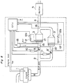
- Fig. 1 shows a block diagram of the first embodiment in accordance with the present invention.
- reference numeral 1 denotes an engine
- 2 denotes a first pipe for leading the exhaust gas of the engine into a filter
- 3 denotes a filter that cleans exhaust gas by impacting particulate matter of carbon components and others in exhaust gas
- 4 denotes a second pipe that leads exhaust gas discharged from filter 3 into a muffler 5, which reduces exhaust sound.
- 6 denotes a by-pass pipe that connects first pipe 2 and second pipe 4 to lead exhaust gas into muffler 5 bypassing filter 3
- 7 denotes a controller that controls valves 8, 9, a heating system 17, a blower 18 and others based on the outputs of engine 1, temperature detectors 13, 14, and pressure sensors 15, 16.
- Controller 7 comprises a CPU and memory.
- 8 denotes a valve installed inside first pipe 1 and controls the flow of exhaust gas into filter 3.
- the present embodiment uses a valve such that a disk is rotated to control the flow in a pipe.
- 9 denotes a valve of the same type and controls the flow in by-pass pipe 6.
- 10 and 11 denote actuator that respectively actuate valves 8 and 9, and the present embodiment uses a stepping motor to control them open loop.
- FIG. 12 denotes a battery that stores energy for burning up carbon components captured and deposited in filter 3, and the present embodiment uses type 24V300Ah.
- Battery 12 is charged by a dynamo, and its switch 12 is set to turn ON by controller 7 to provide an electric current to heating system 17 to burn up carbon components deposited in filter 3.
- 13 and 14 denote temperature detectors that detect the temperature T1 of exhaust gas in pipe 2 and the temperature T2 of filter 3, and the present invention uses thermo-couples.
- Temperature detector 14 may be installed in the rear of filter 3.
- 15 and 16 denote pressure sensors that detect the pressures P1 and P2 of exhaust gas in the pipes, and the present embodiment uses pressure sensors comprising semiconductors.
- 18 denotes a blower that blows air into filter 3 to prompt the burnup of carbon components in filter 3.
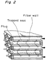
- Fig. 2 shows a partially cut perspective view of filter 3 used in the present embodiment.
- the material of filter 3 is mullite (3Al2O3 ⁇ 2SiO2), and the structure of the filter is fiber.
- Step 301 initializes temperature detectors 13, 14, pressure sensors 15, 16, valves 8, 9, and others.
- Valve 8 is initialised to the open state, and valve 9 is initialized to the closed state.
- Step 302 detects the temperature T1 of the exhaust gas and the temperature T2 of filter 3.
- Step 303 compares the detected temperatures T1 and T2, and if the difference between T1 and T2 is greater than or equal to a constant, then the operation goes to Step 313; otherwise, the operation goes to 304.
- the constant is set to 300 °C in the present embodiment.
- Step 303 judges that the difference between T1 and T2 is greater than or equal to 300 °C, then Step 313 opens valve 8 by 20% and opens valve 9 by 80% to prevent hot exhaust gas from rapidly flowing into filter 3, while sending a small quantity of exhaust gas into filter 3 to gradually increase the temperature of filter 3. Then the operation returns to Step 302 to detect the temperatures T1 and T2 again. If Step 303 judges that the difference between T1 and T2 is less than 300 °C, then Step 304 judges if the difference is greater than or equal to 250 °C.
- Step 314 opens valve 8 by 70% and opens valve 9 by 30%, so that more exhaust gas flows into filter 3, and the temperature of the filter increases.
- Step 305, 306, and 307 classifies the temperature difference between T1 and T2, and the opening of the valves are performed depending on the classified cases and based on previously calculated results. Specifically, as shown in Fig. 3, if the temperature difference is 200 °C ⁇ 250 °C, Step 315 opens valve 8 by 50% and valve 9 by 50%. If the temperature difference is 150 °C ⁇ 200 °C, then Step 306 opens valve 8 by 70% and valve 9 by 30%.
- Step 307 opens valve 8 by 80% and valve 9 by 20%. If the temperature difference is less than 100 °C, then Step 308 opens valve 8 by 100% and closes valve 9. In this way, by preventing a great amount of exhaust gas of high temperature from rapidly flowing into filter 3 and by gradually increasing the temperature of filter 3, the present embodiment prevents cracking of filter 3.
- Fig. 4 shows how the temperature of filter 3 increases after the starting of the engine, when an apparatus of the present embodiment is used. As seen from Fig. 4, the temperature of filter 3 increases with a smaller temperature gradient than a conventional apparatus.
- the apparatus does not perform the above operation. However, if the temperature difference between filter 3 and the exhaust gas becomes exceedingly high by some causes, then the above operation is performed to prevent cracking of filter 3. For example, if the driver wants to travel at the maximum power of the engine, he may close valve 8 and open valve 9 not to use filter 3. Further, if only urban areas are exhaust-gas regulated, then the driver may use filter 3 only when traveling in an urban area and may travel on roads outside urban areas without using filter 3. In these cases, filter 3 is cooled to become a normal temperature, so that the operation should be applied to prevent cracking of filter 3.
- Step 309 measures and detects the pressures P1, P2 of the exhaust gas in the first pipe and the second pipe by pressure sensors 15, 16.
- Step 310 compares the detected pressures P1 and P2. If the difference between P1 and P2 is greater than a constant, then filter 3 is judged to be stuffed and malfunctioning, and the operation goes to Step 311. Since the present embodiment uses a cylindrical filter 5. 66 inches in diameter and 6.00 inches long, the carbon components deposited in filter 3 are burned up, when the pressure difference between P1 and P2 reaches 1000 mmAq. The predetermined constant for the pressure difference depends on the shape and material of filter 3. Step 311 heats up filter 3 by heating system 16 and blows air in by blower 17, so that the deposited soot or the like is burned up and filter 3 is made cleanly reactivated.
- Fig. 5 shows a flowchart of the burnup operation of carbon components. Since this operation is the same as a prior one, its description is omitted. Although no indicated in the flowchart, catalysts may be used to lower the combustion temperature as in a prior operation. After carbon components are burned up by Step 31, the operation of the apparatus for cleaning exhaust gas of the present embodiment returns to Step 302 and repeats the same routine described above.
- the present embodiment detects the temperature of exhaust gas flowing into filter 3, and if the detected temperature is greatly different from the temperature of filter 3, then valves 8 and 9 are controlled so that too large quantity of exhaust gas of high temperature is not impacted against filter 3. As a result, cracking of filter 3 due to a rapid temperature change can be prevented.
- Fig. 6 shows a block diagram of the present embodiment.
- a component similar to one in the first embodiment has the same number.
- the second embodiment is different from the first embodiment in that temperature detectors 13 and 14 are omitted.
- the present embodiment simplifies and improves the first embodiment.
- the reason for omitting temperature detectors are as follows. A change of temperature that destroys filter 3 occurs, when exhaust gas of high temperature flows into cool filter 3 immediately after the engine is started or after driving without using filter 3. Therefore, The same effects as those of the first embodiments are obtained if a similar operation of gradually giving exhaust gas to filter 3 as in the first embodiment is performed immediately after the starting of the engine or after a period of not using filter 3.
- the present embodiment performs an initial operation of the apparatus for purifying exhaust gas, if controller 7 detects the starting of engine 1.
- composition of the present embodiment is omitted, since it is almost the same as that of the first embodiment.
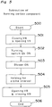
- Fig. 7 shows a flowchart of the operation of the present embodiment.
- Step 700 if the engine starts, this exhaust gas purifying routine starts (Step 700).
- Step 701 sets initial values and initializes valves 8, 9 and pressure sensors 15, 16.
- Steps 703 to 708 performs an initial operation by controlling valves 8 and 9. Specifically, Step 703 opens valve 8 by 20% and valve 9 by 80%. This state of valves 8, 9 lasts 5 seconds. This time period of 5 seconds can be counted using the clock frequency of the CPU.
- Step 704 opens valve 8 by 30% and valve 9 by 70%.
- Step 705 opens valve 8 by 50% and valve 9 by 30%
- Step 706 opens valve 8 by 70% and valve 9 by 30%
- Step 707 opens valve 8 by 80% and valve 9 by 20%
- Step 708 opens valve 8 by 100% and closes valve 9.
- the present embodiment assigns a time period of 5 seconds to each of Steps 703 to 708.
- Steps 701 to 708 are the initial operation, by which a rapid change of temperature and cracking of filter 3 are prevented.
- the operation proceeds with Steps 709, 710, 711, which are the same as Steps 309, 310, 311 of the first embodiment so that their description is omitted here. How the temperature of filter 3 increases when the above initial operation is performed is almost the same as the temperature change in the first embodiment shown in Fig. 4.
- controller 7 holds information on the rates and duration of the openings of valves 8, 9, so that the above operation is performed to prevent cracking of filter 3, if the time during which valve 8 is closed has become more than a predetermined period, for example, 2 minutes.
- the present embodiment controls valves 8, 9 not to give a rapid change of temperature to filter 3 by performing the initial operation depending on the time passing after the starting of the engine without using temperature detectors. Therefore, exhaust gas of high temperature does not rushing into filter 3, so that cracking of filter 3 can be prevented.
- valves 8 and 9 are performed stepwise in both the first and the second embodiments. However, this control may be performed continuously.
- the present embodiment also digitize the outputs of all the sensors, and controller 7 is programmed using a CPU and memory. However, the operation of controller can be realized by analog circuits.
- Fig. 8 shows a third embodiment of the present invention.
- the present embodiment provides one more filter 3' on the way of bypass pipe 6.
- two filters 3 and 3' are arranged in parallel to each other between engine 1 and muffler 5.
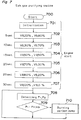
- Fig. 9 is a flowchart of exhaust gas purifying routine in the third preferred embodiment. As is apparent from comparison of Fig. 9 with Fig. 7, steps from 900 to 911 correspond to steps 700 to 711 of Fig. 7. Only differences are that valve 9 is replaced to valve 8' in Fig. 9 and rates of opening and closing of valves 8 and 8' are differentiated from those in the second preferred embodiment.
- this routine starts in response to the engine start, valves 8 and 8' are opened by 50% for first five seconds, respectively (Step 902). From 5 to 10 second, valves 8 and 8' are opened by 60% and 40%, respectively (Step 903).
- valve 8 is increased by 10% for every five seconds and that of valve 8' is decreased by 10% for every five seconds (Steps 904 to 907).
- valve 8 is opened fully and valve 8' is closed completely.
- all exhaust gas can be purified even during the engine start.
- filter 3' may be identical to filter 3.
- filters 3 and 3' are useable as the main filter alternatively.
- Fig. 10 shows a fourth embodiment of the present invention wherein there are provided two filters 3 and 3' arranged in parallel to each other and a bypass pipe 6 without any filter.
- Fig. 11 shows a flowchart of exhaust gas purifying routine by the fourth embodiment.
- Steps 1100 to 1110 of Fig. 11 correspond to Steps 900 to 910 of Fig. 9 one to one.
- the opening rate of valve 8 is increased 20% ⁇ 30% ⁇ 40% ⁇ 60% ⁇ 80% ⁇ 100% for every five seconds. That of valve 8' is increased first 20% ⁇ 30% ⁇ 40% until 15 seconds and, then, decreased 40% ⁇ 20% ⁇ 0% for remaining 15 seconds.
- Valve 9 is opened by 60% for first five seconds and, thereafter, is gradually closed 40% ⁇ 20% ⁇ 0% and, after 20 seconds elapsed, it is closed completely.
- amount of unpurified exhaust gas can be minimized when compared with the first and second preferred embodiments.
- the third and fourth embodiments are directed to the exhaust gas purifying during the engine start, they are applicable to the thermal control of filter as mentioned regarding the first preferred embodiment of the present invention.
- the present invention prevents a rapid change of temperature and cracking of the exhaust gas filter, so that durable apparatus for cleaning exhaust gas can be provided.
Landscapes
- Engineering & Computer Science (AREA)
- Chemical & Material Sciences (AREA)
- Combustion & Propulsion (AREA)
- Mechanical Engineering (AREA)
- General Engineering & Computer Science (AREA)
- Processes For Solid Components From Exhaust (AREA)
Applications Claiming Priority (2)
| Application Number | Priority Date | Filing Date | Title |
|---|---|---|---|
| JP4240316A JP2894103B2 (ja) | 1992-09-09 | 1992-09-09 | 排気ガス浄化装置 |
| JP240316/92 | 1992-09-09 |
Publications (3)
| Publication Number | Publication Date |
|---|---|
| EP0601287A2 true EP0601287A2 (de) | 1994-06-15 |
| EP0601287A3 EP0601287A3 (en) | 1994-08-17 |
| EP0601287B1 EP0601287B1 (de) | 1998-08-19 |
Family
ID=17057657
Family Applications (1)
| Application Number | Title | Priority Date | Filing Date |
|---|---|---|---|
| EP93114483A Expired - Lifetime EP0601287B1 (de) | 1992-09-09 | 1993-09-09 | Vorrichtung zur Reinigung von Abgasen einer Dieselbrennkraftmaschine |
Country Status (4)
| Country | Link |
|---|---|
| US (1) | US5489319A (de) |
| EP (1) | EP0601287B1 (de) |
| JP (1) | JP2894103B2 (de) |
| DE (1) | DE69320445T2 (de) |
Cited By (9)
| Publication number | Priority date | Publication date | Assignee | Title |
|---|---|---|---|---|
| EP0891806A2 (de) * | 1997-07-19 | 1999-01-20 | Volkswagen Aktiengesellschaft | Verfahren und Vorrichtung zur Regeneration einer Schwefelfalle |
| EP0892158A3 (de) * | 1997-07-19 | 1999-04-21 | Volkswagen Aktiengesellschaft | Verfahren und Vorrichtung zur Überwachung der De-Sulfatierung bei NOx-Speicherkatalysatoren |
| EP1270885A3 (de) * | 2001-06-20 | 2004-12-15 | Isuzu Motors Limited | Vorrichtung zur Abgasreinigung eines Dieselmotors |
| EP1882831A1 (de) * | 2006-07-25 | 2008-01-30 | Mann+Hummel Gmbh | Abgasanlage eines Dieselmotors |
| EP2137388A1 (de) * | 2007-04-16 | 2009-12-30 | Volvo Lastvagnar AB | Vorrichtung zur verwendung in einem abgasnachbehandlungssystem |
| US7640729B2 (en) | 2004-09-25 | 2010-01-05 | Robert Bosch Gmbh | Method for operating a particulate filter situated in the exhaust gas area of an internal combustion engine and device for carrying out the method |
| EP1914399B1 (de) * | 2006-10-17 | 2010-03-10 | Ibiden Co., Ltd. | Abgasreinigungsvorrichtung |
| GB2467949A (en) * | 2009-02-20 | 2010-08-25 | Clive Robert Rich | Apparatus for improving the operation of a particulate filter by heating |
| US8127592B2 (en) * | 2006-10-17 | 2012-03-06 | Ibiden Co., Ltd. | Particulate matter detection sensor |
Families Citing this family (56)
| Publication number | Priority date | Publication date | Assignee | Title |
|---|---|---|---|---|
| US5582002A (en) * | 1994-06-29 | 1996-12-10 | Pattas; Konstantin | Method of and an apparatus for controlled regeneration of a diesel soot filter |
| US5674634A (en) * | 1994-12-05 | 1997-10-07 | E. I. Du Pont De Nemours And Company | Insulator composition, green tape, and method for forming plasma display apparatus barrier-rib |
| JP3266749B2 (ja) * | 1994-12-28 | 2002-03-18 | 三菱電機株式会社 | 内燃機関の排気ガス浄化装置 |
| JPH08232643A (ja) * | 1995-02-28 | 1996-09-10 | Matsushita Electric Ind Co Ltd | 排ガス浄化方法及び排ガス浄化装置 |
| FR2747941B1 (fr) * | 1996-04-30 | 1998-05-15 | Commissariat Energie Atomique | Filtre electrostatique a procede de decolmatage rapide sans rupture de confinement |
| US6010547A (en) * | 1998-01-13 | 2000-01-04 | Korea Institute Of Machinery And Materials | Counterflow type particulate matter filter trap system having metal fiber filter |
| FR2778118B1 (fr) * | 1998-04-29 | 2000-06-02 | Inst Francais Du Petrole | Procede et dispositif de regeneration locale et controlee d'un filtre a particules |
| JP3557925B2 (ja) * | 1998-12-22 | 2004-08-25 | トヨタ自動車株式会社 | 内燃機関の排気浄化装置 |
| US6365108B1 (en) * | 1999-10-12 | 2002-04-02 | Caterpillar Inc. | Siloxane filter for O2 sensor for bio-gas engine |
| DE19959870A1 (de) * | 1999-12-10 | 2001-06-21 | Heraeus Electro Nite Int | Meßanordnung und Verfahren zur Überwachung der Funktionsfähigkeit eines Rußfilters |
| US6347511B1 (en) | 1999-12-21 | 2002-02-19 | Ford Global Technologies, Inc. | Exhaust gas purification system for lean burn engine |
| JP2001329830A (ja) | 2000-03-15 | 2001-11-30 | Ibiden Co Ltd | 排気ガス浄化フィルタの再生装置及びフィルタ再生方法、排気ガス浄化フィルタの再生プログラム及びそのプログラムを格納する記録媒体 |
| US6823665B2 (en) * | 2000-07-24 | 2004-11-30 | Toyota Jidosha Kabushiki Kaisha | Exhaust gas purification device |
| ES2250433T3 (es) * | 2000-07-24 | 2006-04-16 | Toyota Jidosha Kabushiki Kaisha | Dispositivo de control de la emision de escape de un motor de combustion interna. |
| US6725652B2 (en) * | 2000-10-03 | 2004-04-27 | Isuzu Motors Ltd. | Diesel particulate filtering device |
| US6422001B1 (en) * | 2000-10-10 | 2002-07-23 | Bae Systems Controls Inc. | Regeneration control of particulate filter, particularly in a hybrid electric vehicle |
| US6405528B1 (en) * | 2000-11-20 | 2002-06-18 | Ford Global Technologies, Inc. | Method for determining load on particulate filter for engine exhaust, including estimation of ash content |
| US6642489B2 (en) * | 2001-01-09 | 2003-11-04 | Applied Materials, Inc. | Method and apparatus for improving exhaust gas consumption in an exhaust conduit |
| JP2002349241A (ja) * | 2001-05-24 | 2002-12-04 | Isuzu Motors Ltd | ディーゼルエンジンの排気浄化装置 |
| JP3876705B2 (ja) * | 2001-12-13 | 2007-02-07 | いすゞ自動車株式会社 | ディーゼルエンジンの排気ガス浄化システム |
| AU2002351384A1 (en) * | 2002-04-12 | 2003-10-27 | Illinois Valley Holding Company | APPARATUS AND METHOD FOR FILTERING PARTICULATE AND REDUCING NOx EMISSIONS |
| JP4075573B2 (ja) * | 2002-06-13 | 2008-04-16 | 株式会社デンソー | 内燃機関の排ガス浄化装置 |
| US7326269B2 (en) * | 2003-01-31 | 2008-02-05 | Engineered Support Systems, Inc. | NBC filtration unit providing unfiltered and filtered air paths |
| US20040226287A1 (en) * | 2003-02-18 | 2004-11-18 | Edgar Bradley L. | Automated regeneration apparatus and method for a particulate filter |
| US7992382B2 (en) * | 2003-08-01 | 2011-08-09 | Illinois Valley Holding Company | Particulate trap system and method |
| KR100534737B1 (ko) * | 2003-10-24 | 2005-12-07 | 현대자동차주식회사 | 디젤 엔진의 입자상 물질 저감 시스템 및 저감 방법 |
| JP4415749B2 (ja) * | 2004-05-10 | 2010-02-17 | 株式会社デンソー | 内燃機関の排気浄化装置 |
| JP2006029239A (ja) * | 2004-07-16 | 2006-02-02 | Toyota Motor Corp | 排気浄化フィルタ過熱防止装置 |
| US7332016B2 (en) * | 2004-07-30 | 2008-02-19 | Caterpillar Inc. | Particulate trap with selective blocking element |
| US7418815B2 (en) * | 2004-07-30 | 2008-09-02 | Caterpillar Inc. | Particulate trap with electrostatic precipitator |
| US7251932B2 (en) * | 2004-11-08 | 2007-08-07 | Southwest Research Institute | Exhaust system and method for controlling exhaust gas flow and temperature through regenerable exhaust gas treatment devices |
| US20060223690A1 (en) * | 2005-04-01 | 2006-10-05 | Tsutomu Mutoh | Photosensitive thick-film dielectric paste composition and method for making an insulating layer using same |
| US7340888B2 (en) * | 2005-04-26 | 2008-03-11 | Donaldson Company, Inc. | Diesel particulate matter reduction system |
| US7481048B2 (en) * | 2005-06-30 | 2009-01-27 | Caterpillar Inc. | Regeneration assembly |
| US7468085B2 (en) * | 2005-12-19 | 2008-12-23 | Caterpillar Inc. | System and method for cleaning a filter |
| US20070158466A1 (en) * | 2005-12-29 | 2007-07-12 | Harmon Michael P | Nozzle assembly |
| US7862640B2 (en) | 2006-03-21 | 2011-01-04 | Donaldson Company, Inc. | Low temperature diesel particulate matter reduction system |
| US20070228191A1 (en) * | 2006-03-31 | 2007-10-04 | Caterpillar Inc. | Cooled nozzle assembly for urea/water injection |
| US20070235556A1 (en) * | 2006-03-31 | 2007-10-11 | Harmon Michael P | Nozzle assembly |
| EP1916394B1 (de) * | 2006-10-17 | 2009-03-25 | Ibiden Co., Ltd. | Abgasreinigungsvorrichtung und entsprechendes Verfahren sowie ein Verfahren zur Messung der Partikel |
| US7631492B2 (en) * | 2006-12-20 | 2009-12-15 | Suresh Arvind S | System and method for inhibiting uncontrolled regeneration of a particulate filter for an internal combustion engine |
| US7721536B2 (en) * | 2007-05-18 | 2010-05-25 | International Truck Intellectual Property Company, Llc | Particulate filter having expansible capture structure for particulate removal |
| DE102008010658B4 (de) * | 2008-02-22 | 2010-08-19 | Knorr-Bremse Systeme für Nutzfahrzeuge GmbH | Abgasregelsystem und Abgasregelverfahren |
| US20100064666A1 (en) * | 2008-09-15 | 2010-03-18 | Wen-Lo Chen | Carbon deposition elimination method |
| WO2011036772A1 (ja) * | 2009-09-25 | 2011-03-31 | イビデン株式会社 | 微粒子センサ及び排ガス浄化装置 |
| US8534055B2 (en) * | 2010-03-29 | 2013-09-17 | Thermo King Corporation | Filter arrangement for exhaust aftertreatment system |
| WO2013063137A1 (en) * | 2011-10-26 | 2013-05-02 | Boshart Automotive Testing Service, Inc. | Over temperature / pressure safety device for diesel particulate filters |
| DE102016001792A1 (de) * | 2015-02-26 | 2016-09-01 | Ngk Spark Plug Co., Ltd. | Partikelsammelsystem und Partikelsammelvorrichtung |
| DE102015211169A1 (de) * | 2015-06-17 | 2016-12-22 | Mtu Friedrichshafen Gmbh | Verfahren zum Betreiben eines Abgasnachbehandlungssystems, Abgasnachbehandlungssystem und Brennkraftmaschine mit einem Abgasnachbehandlungssystem |
| US20180128145A1 (en) * | 2016-11-09 | 2018-05-10 | Ford Global Technologies, Llc | Method and system for an exhaust diverter valve |
| CN107060953A (zh) * | 2017-04-13 | 2017-08-18 | 江苏豪赛科技股份有限公司 | 柴油发电机组烟羽微粒捕集装置及方法 |
| DE102018106588A1 (de) * | 2018-03-21 | 2019-09-26 | Dr. Ing. H.C. F. Porsche Aktiengesellschaft | Abgasanlage sowie Verfahren zum Betreiben einer Abgasanlage |
| JP7119874B2 (ja) * | 2018-10-10 | 2022-08-17 | トヨタ自動車株式会社 | 内燃機関の制御装置、内燃機関及び車両 |
| CN112796855B (zh) * | 2019-11-14 | 2022-07-01 | 广州汽车集团股份有限公司 | 车辆排气颗粒补集再生装置及其方法、车辆 |
| JP2022147445A (ja) * | 2021-03-23 | 2022-10-06 | 株式会社デンソーウェーブ | ガス燃焼器 |
| US11535238B2 (en) * | 2021-04-12 | 2022-12-27 | Ford Global Technologies, Llc | Exhaust heating system to reduce engine cold start emissions |
Citations (6)
| Publication number | Priority date | Publication date | Assignee | Title |
|---|---|---|---|---|
| JPS58128413A (ja) * | 1982-01-27 | 1983-08-01 | Nissan Motor Co Ltd | 内燃機関の排気浄化装置 |
| US4512147A (en) * | 1983-01-07 | 1985-04-23 | Cummins Engine Company, Inc. | Method and apparatus for removing carbon particles from engine exhausts |
| US4803838A (en) * | 1987-12-24 | 1989-02-14 | Kaeser Henry E | Diesel particulate infusion controller |
| DE3806219A1 (de) * | 1988-02-26 | 1989-09-07 | Pattas Konstantin N | Russfiltersystem |
| DE4042048A1 (de) * | 1989-12-28 | 1991-07-04 | Nissan Motor | Abgasreinigungsvorrichtung fuer eine verbrennungsmaschine mit innenverbrennung |
| WO1991013242A1 (en) * | 1990-02-21 | 1991-09-05 | Southwest Research Institute | Device and method for regeneration of an internal combustion exhaust particulate trap |
Family Cites Families (17)
| Publication number | Priority date | Publication date | Assignee | Title |
|---|---|---|---|---|
| JPS578311A (en) * | 1980-06-19 | 1982-01-16 | Toyota Motor Corp | Method and device for decreasing discharged quantity of diesel particulates |
| JPS5928009A (ja) * | 1982-08-06 | 1984-02-14 | Toyota Motor Corp | デイ−ゼルエンジンの排気微粒子浄化装置 |
| JPS59153914A (ja) * | 1983-02-21 | 1984-09-01 | Nissan Motor Co Ltd | 内燃機関における排気微粒子捕集用トラツプの再生用バ−ナ−の制御装置 |
| JPS60122214A (ja) * | 1983-11-30 | 1985-06-29 | Tokyo Roki Kk | 内燃機関の排ガス中の黒煙除去方法及び装置 |
| US4544388A (en) * | 1983-12-27 | 1985-10-01 | Ford Motor Company | Apparatus for periodically oxidizing particulates collected from exhaust gases |
| EP0168388B1 (de) * | 1983-12-27 | 1988-05-04 | Ford Motor Company Limited | Automatische startanlage zur regeneration eines partikelabscheidfilters |
| JPS61424A (ja) * | 1984-06-12 | 1986-01-06 | Nippon Denso Co Ltd | セラミツクフイルタ |
| US4651524A (en) * | 1984-12-24 | 1987-03-24 | Arvin Industries, Inc. | Exhaust processor |
| US4665690A (en) * | 1985-01-14 | 1987-05-19 | Mazda Motor Corporation | Exhaust gas cleaning system for vehicle |
| JPH01159029A (ja) * | 1987-12-16 | 1989-06-22 | Toyota Motor Corp | ディーゼルエンジンの排気浄化装置 |
| JPH0621546B2 (ja) * | 1988-03-11 | 1994-03-23 | 工業技術院長 | 排気中微粒子処理方法及び装置 |
| DE3832790C2 (de) * | 1988-09-27 | 1997-12-11 | Pattas Konstantin N | Verfahren und Einrichtung zum Regenerieren eines Rußfilters |
| JPH0621552B2 (ja) * | 1989-02-13 | 1994-03-23 | いすゞ自動車株式会社 | パティキュレートトラップの再燃焼装置 |
| JPH0623538B2 (ja) * | 1989-03-30 | 1994-03-30 | いすゞ自動車株式会社 | パティキュレートトラップの再燃焼装置 |
| JPH0621551B2 (ja) * | 1989-06-16 | 1994-03-23 | いすゞ自動車株式会社 | パティキュレートトラップの再生装置 |
| GB2239407B (en) * | 1989-12-27 | 1994-10-12 | Nissan Motor | Exhaust gas purifying device for an internal combustion engine |
| US5085049A (en) * | 1990-07-09 | 1992-02-04 | Rim Julius J | Diesel engine exhaust filtration system and method |
-
1992
- 1992-09-09 JP JP4240316A patent/JP2894103B2/ja not_active Expired - Fee Related
-
1993
- 1993-09-09 EP EP93114483A patent/EP0601287B1/de not_active Expired - Lifetime
- 1993-09-09 DE DE69320445T patent/DE69320445T2/de not_active Expired - Fee Related
- 1993-09-09 US US08/123,854 patent/US5489319A/en not_active Expired - Lifetime
Patent Citations (6)
| Publication number | Priority date | Publication date | Assignee | Title |
|---|---|---|---|---|
| JPS58128413A (ja) * | 1982-01-27 | 1983-08-01 | Nissan Motor Co Ltd | 内燃機関の排気浄化装置 |
| US4512147A (en) * | 1983-01-07 | 1985-04-23 | Cummins Engine Company, Inc. | Method and apparatus for removing carbon particles from engine exhausts |
| US4803838A (en) * | 1987-12-24 | 1989-02-14 | Kaeser Henry E | Diesel particulate infusion controller |
| DE3806219A1 (de) * | 1988-02-26 | 1989-09-07 | Pattas Konstantin N | Russfiltersystem |
| DE4042048A1 (de) * | 1989-12-28 | 1991-07-04 | Nissan Motor | Abgasreinigungsvorrichtung fuer eine verbrennungsmaschine mit innenverbrennung |
| WO1991013242A1 (en) * | 1990-02-21 | 1991-09-05 | Southwest Research Institute | Device and method for regeneration of an internal combustion exhaust particulate trap |
Non-Patent Citations (1)
| Title |
|---|
| PATENT ABSTRACTS OF JAPAN vol. 007, no. 240 (M-251) (1385) 25 October 1983 & JP-A-58 128 413 (NISSAN) 1 August 1983 * |
Cited By (12)
| Publication number | Priority date | Publication date | Assignee | Title |
|---|---|---|---|---|
| EP0891806A2 (de) * | 1997-07-19 | 1999-01-20 | Volkswagen Aktiengesellschaft | Verfahren und Vorrichtung zur Regeneration einer Schwefelfalle |
| EP0892158A3 (de) * | 1997-07-19 | 1999-04-21 | Volkswagen Aktiengesellschaft | Verfahren und Vorrichtung zur Überwachung der De-Sulfatierung bei NOx-Speicherkatalysatoren |
| EP0891806A3 (de) * | 1997-07-19 | 1999-04-21 | Volkswagen Aktiengesellschaft | Verfahren und Vorrichtung zur Regeneration einer Schwefelfalle |
| EP1270885A3 (de) * | 2001-06-20 | 2004-12-15 | Isuzu Motors Limited | Vorrichtung zur Abgasreinigung eines Dieselmotors |
| US7640729B2 (en) | 2004-09-25 | 2010-01-05 | Robert Bosch Gmbh | Method for operating a particulate filter situated in the exhaust gas area of an internal combustion engine and device for carrying out the method |
| EP1882831A1 (de) * | 2006-07-25 | 2008-01-30 | Mann+Hummel Gmbh | Abgasanlage eines Dieselmotors |
| EP1914399B1 (de) * | 2006-10-17 | 2010-03-10 | Ibiden Co., Ltd. | Abgasreinigungsvorrichtung |
| US7891176B2 (en) | 2006-10-17 | 2011-02-22 | Ibiden Co., Ltd. | Exhaust gas purifying apparatus |
| US8127592B2 (en) * | 2006-10-17 | 2012-03-06 | Ibiden Co., Ltd. | Particulate matter detection sensor |
| EP2137388A1 (de) * | 2007-04-16 | 2009-12-30 | Volvo Lastvagnar AB | Vorrichtung zur verwendung in einem abgasnachbehandlungssystem |
| EP2137388A4 (de) * | 2007-04-16 | 2013-05-22 | Volvo Lastvagnar Ab | Vorrichtung zur verwendung in einem abgasnachbehandlungssystem |
| GB2467949A (en) * | 2009-02-20 | 2010-08-25 | Clive Robert Rich | Apparatus for improving the operation of a particulate filter by heating |
Also Published As
| Publication number | Publication date |
|---|---|
| US5489319A (en) | 1996-02-06 |
| DE69320445T2 (de) | 1999-02-18 |
| EP0601287B1 (de) | 1998-08-19 |
| JP2894103B2 (ja) | 1999-05-24 |
| JPH0693828A (ja) | 1994-04-05 |
| EP0601287A3 (en) | 1994-08-17 |
| DE69320445D1 (de) | 1998-09-24 |
Similar Documents
| Publication | Publication Date | Title |
|---|---|---|
| EP0601287A2 (de) | Vorrichtung zur Reinigung von Abgasen einer Dieselbrennkraftmaschine | |
| JP3355943B2 (ja) | 排ガス浄化方法及び排ガスフィルタ並びにこれを用いた排ガスフィルタ浄化装置 | |
| US5458673A (en) | Exhaust gas particulate purifying process for internal combustion engine | |
| US4346557A (en) | Incineration-cleanable composite diesel exhaust filter and vehicle equipped therewith | |
| US5097665A (en) | Flattened profile diesel engine exhaust oxidizer | |
| US6447564B1 (en) | Regeneration system for an exhaust gas cleaning device | |
| US6770116B2 (en) | Regeneration device of exhaust gas purification filter and filter regeneration method | |
| CA2183537C (en) | A flow-through particulate incineration system coupled to an aerodynamically regenerated particulate trap for diesel engine exhaust gas | |
| US5121601A (en) | Diesel engine exhaust oxidizer | |
| JPH05240027A (ja) | 排気微粒子浄化装置 | |
| JP3264707B2 (ja) | 内燃機関の排気ガス微粒子浄化装置 | |
| JPH0771226A (ja) | 排気微粒子浄化装置 | |
| JPH08170522A (ja) | ディーゼル機関排ガス浄化装置 | |
| JP2957865B2 (ja) | 逆洗式パティキュレート捕集装置 | |
| JPH08218847A (ja) | ディーゼル機関の排気浄化方法 | |
| JPH10266826A (ja) | ディーゼルエンジンの排気ガス処理装置 | |
| JPH037010B2 (de) | ||
| KR20030021454A (ko) | 디젤엔진의 배기가스 후 처리시스템과 그 작동방법 | |
| JP3580563B2 (ja) | 内燃機関の排気ガス微粒子浄化装置 | |
| JPH06241022A (ja) | 排気浄化装置 | |
| JP3114357B2 (ja) | 排気フィルタの再生装置 | |
| JP3254860B2 (ja) | 排気ガス処理装置 | |
| JP3073375B2 (ja) | 排気ガス浄化装置 | |
| JP2816375B2 (ja) | パティキュレートトラップ機構 | |
| JPH05195748A (ja) | 内燃機関の排気浄化装置 |
Legal Events
| Date | Code | Title | Description |
|---|---|---|---|
| PUAI | Public reference made under article 153(3) epc to a published international application that has entered the european phase |
Free format text: ORIGINAL CODE: 0009012 |
|
| 17P | Request for examination filed |
Effective date: 19930911 |
|
| AK | Designated contracting states |
Kind code of ref document: A2 Designated state(s): DE FR GB |
|
| PUAL | Search report despatched |
Free format text: ORIGINAL CODE: 0009013 |
|
| AK | Designated contracting states |
Kind code of ref document: A3 Designated state(s): DE FR GB |
|
| 17Q | First examination report despatched |
Effective date: 19951219 |
|
| GRAG | Despatch of communication of intention to grant |
Free format text: ORIGINAL CODE: EPIDOS AGRA |
|
| GRAG | Despatch of communication of intention to grant |
Free format text: ORIGINAL CODE: EPIDOS AGRA |
|
| GRAH | Despatch of communication of intention to grant a patent |
Free format text: ORIGINAL CODE: EPIDOS IGRA |
|
| GRAH | Despatch of communication of intention to grant a patent |
Free format text: ORIGINAL CODE: EPIDOS IGRA |
|
| GRAA | (expected) grant |
Free format text: ORIGINAL CODE: 0009210 |
|
| AK | Designated contracting states |
Kind code of ref document: B1 Designated state(s): DE FR GB |
|
| REF | Corresponds to: |
Ref document number: 69320445 Country of ref document: DE Date of ref document: 19980924 |
|
| ET | Fr: translation filed | ||
| PLBE | No opposition filed within time limit |
Free format text: ORIGINAL CODE: 0009261 |
|
| STAA | Information on the status of an ep patent application or granted ep patent |
Free format text: STATUS: NO OPPOSITION FILED WITHIN TIME LIMIT |
|
| 26N | No opposition filed | ||
| REG | Reference to a national code |
Ref country code: GB Ref legal event code: IF02 |
|
| PGFP | Annual fee paid to national office [announced via postgrant information from national office to epo] |
Ref country code: GB Payment date: 20060906 Year of fee payment: 14 |
|
| PGFP | Annual fee paid to national office [announced via postgrant information from national office to epo] |
Ref country code: DE Payment date: 20060907 Year of fee payment: 14 |
|
| PGFP | Annual fee paid to national office [announced via postgrant information from national office to epo] |
Ref country code: FR Payment date: 20060908 Year of fee payment: 14 |
|
| GBPC | Gb: european patent ceased through non-payment of renewal fee |
Effective date: 20070909 |
|
| PG25 | Lapsed in a contracting state [announced via postgrant information from national office to epo] |
Ref country code: DE Free format text: LAPSE BECAUSE OF NON-PAYMENT OF DUE FEES Effective date: 20080401 |
|
| REG | Reference to a national code |
Ref country code: FR Ref legal event code: ST Effective date: 20080531 |
|
| PG25 | Lapsed in a contracting state [announced via postgrant information from national office to epo] |
Ref country code: FR Free format text: LAPSE BECAUSE OF NON-PAYMENT OF DUE FEES Effective date: 20071001 |
|
| PG25 | Lapsed in a contracting state [announced via postgrant information from national office to epo] |
Ref country code: GB Free format text: LAPSE BECAUSE OF NON-PAYMENT OF DUE FEES Effective date: 20070909 |