EP0598300A1 - Reifenlauffläche - Google Patents
Reifenlauffläche Download PDFInfo
- Publication number
- EP0598300A1 EP0598300A1 EP93118067A EP93118067A EP0598300A1 EP 0598300 A1 EP0598300 A1 EP 0598300A1 EP 93118067 A EP93118067 A EP 93118067A EP 93118067 A EP93118067 A EP 93118067A EP 0598300 A1 EP0598300 A1 EP 0598300A1
- Authority
- EP
- European Patent Office
- Prior art keywords
- tread
- grooves
- lateral
- circumferential
- width
- Prior art date
- Legal status (The legal status is an assumption and is not a legal conclusion. Google has not performed a legal analysis and makes no representation as to the accuracy of the status listed.)
- Granted
Links
Images


Classifications
-
- B—PERFORMING OPERATIONS; TRANSPORTING
- B60—VEHICLES IN GENERAL
- B60C—VEHICLE TYRES; TYRE INFLATION; TYRE CHANGING; CONNECTING VALVES TO INFLATABLE ELASTIC BODIES IN GENERAL; DEVICES OR ARRANGEMENTS RELATED TO TYRES
- B60C11/00—Tyre tread bands; Tread patterns; Anti-skid inserts
- B60C11/03—Tread patterns
- B60C11/13—Tread patterns characterised by the groove cross-section, e.g. for buttressing or preventing stone-trapping
- B60C11/1369—Tie bars for linking block elements and bridging the groove
-
- B—PERFORMING OPERATIONS; TRANSPORTING
- B60—VEHICLES IN GENERAL
- B60C—VEHICLE TYRES; TYRE INFLATION; TYRE CHANGING; CONNECTING VALVES TO INFLATABLE ELASTIC BODIES IN GENERAL; DEVICES OR ARRANGEMENTS RELATED TO TYRES
- B60C11/00—Tyre tread bands; Tread patterns; Anti-skid inserts
- B60C11/03—Tread patterns
- B60C11/0306—Patterns comprising block rows or discontinuous ribs
-
- B—PERFORMING OPERATIONS; TRANSPORTING
- B60—VEHICLES IN GENERAL
- B60C—VEHICLE TYRES; TYRE INFLATION; TYRE CHANGING; CONNECTING VALVES TO INFLATABLE ELASTIC BODIES IN GENERAL; DEVICES OR ARRANGEMENTS RELATED TO TYRES
- B60C11/00—Tyre tread bands; Tread patterns; Anti-skid inserts
- B60C11/03—Tread patterns
- B60C11/04—Tread patterns in which the raised area of the pattern consists only of continuous circumferential ribs, e.g. zig-zag
- B60C11/042—Tread patterns in which the raised area of the pattern consists only of continuous circumferential ribs, e.g. zig-zag further characterised by the groove cross-section
- B60C11/047—Tread patterns in which the raised area of the pattern consists only of continuous circumferential ribs, e.g. zig-zag further characterised by the groove cross-section the groove bottom comprising stone trapping protection elements, e.g. ribs
-
- B—PERFORMING OPERATIONS; TRANSPORTING
- B60—VEHICLES IN GENERAL
- B60C—VEHICLE TYRES; TYRE INFLATION; TYRE CHANGING; CONNECTING VALVES TO INFLATABLE ELASTIC BODIES IN GENERAL; DEVICES OR ARRANGEMENTS RELATED TO TYRES
- B60C11/00—Tyre tread bands; Tread patterns; Anti-skid inserts
- B60C11/03—Tread patterns
- B60C11/11—Tread patterns in which the raised area of the pattern consists only of isolated elements, e.g. blocks
-
- B—PERFORMING OPERATIONS; TRANSPORTING
- B60—VEHICLES IN GENERAL
- B60C—VEHICLE TYRES; TYRE INFLATION; TYRE CHANGING; CONNECTING VALVES TO INFLATABLE ELASTIC BODIES IN GENERAL; DEVICES OR ARRANGEMENTS RELATED TO TYRES
- B60C11/00—Tyre tread bands; Tread patterns; Anti-skid inserts
- B60C11/03—Tread patterns
- B60C11/12—Tread patterns characterised by the use of narrow slits or incisions, e.g. sipes
- B60C11/1204—Tread patterns characterised by the use of narrow slits or incisions, e.g. sipes with special shape of the sipe
- B60C2011/1213—Tread patterns characterised by the use of narrow slits or incisions, e.g. sipes with special shape of the sipe sinusoidal or zigzag at the tread surface
-
- B—PERFORMING OPERATIONS; TRANSPORTING
- B60—VEHICLES IN GENERAL
- B60C—VEHICLE TYRES; TYRE INFLATION; TYRE CHANGING; CONNECTING VALVES TO INFLATABLE ELASTIC BODIES IN GENERAL; DEVICES OR ARRANGEMENTS RELATED TO TYRES
- B60C11/00—Tyre tread bands; Tread patterns; Anti-skid inserts
- B60C11/03—Tread patterns
- B60C11/12—Tread patterns characterised by the use of narrow slits or incisions, e.g. sipes
- B60C11/1236—Tread patterns characterised by the use of narrow slits or incisions, e.g. sipes with special arrangements in the tread pattern
- B60C2011/1254—Tread patterns characterised by the use of narrow slits or incisions, e.g. sipes with special arrangements in the tread pattern with closed sipe, i.e. not extending to a groove
Definitions
- the invention relates to a tread for a pneumatic tire.
- the tread is particularly well suited for use on a drive axle tire for commercial trucks.
- Block element tread patterns achieve a high level of traction performance.
- the block elements provide laterally extending surfaces that enable the tire to grip the roadway and exert high contact pressure between the tire and the roadway.
- the major drawback to the use of block elements in the tread pattern of drive axle tires has been the propensity of such elements to exhibit irregular wear.
- the occurrence of irregular wear occurs in the blocks as a phenomena known in the art as heel-toe wear, and in the shoulders of such a tire a pattern of high-low wear can be exhibited.
- the tread can rapidly and irregularly wear.
- the irregularly worn tire transmits serious road vibration through the truck making the tire unsuitable for use.
- the operator of the vehicle must have the tire removed and have the tread ground to remove the high spots on the tread. By removing tread rubber, it is sometimes feasible to salvage an irregularly worn tire. Naturally, the tread loses many miles of useful life when such a problem occurs.
- Ribbed tires have historically achieved superior wear characteristics. Instead of having individual block elements, these ribbed tires have circumferentially continuous ribs of tread rubber. The ribs often have zigzag sides which provide some lateral edges to assist in providing tractive forces. Unfortunately rib tread patterns do not exhibit the traction characteristics achievable by block tires.
- U.S. Patent No. 4,223,712 describes a pneumatic tire for heavy duty vehicles.
- the tread has a pair of shoulder ribs and three rows of circumferentially elongated block elements, the block elements being designed to convert to ribs after the tire has worn between 30% and 70% of the tread.
- Such a design has some of the benefits of block element traction for part of the tread's useful life. After the tread is partially worn, the tire can presumably be removed from the drive axle position and used in a trailer position.
- the present invention provides a drive axle truck tire tread which employs a combination of block elements and ribs.
- a tire tread made according to the present invention can provide uniform wear and excellent traction characteristics over the expected life of the tread.
- An elastomeric tread for a pneumatic tire is disclosed.
- the tread extends circumferentially about an axis of rotation of the tire.
- the tread has an inner tread surface, a pair of shoulders, a pair of ribs, a plurality of lateral grooves, three circumferential grooves, and two circumferential rows of block elements.
- the shoulders define the lateral edges of a ground engageable surface.
- the axial distance between the lateral edges define the tread width.
- the ribs extend about the axis of rotation and radially outwardly from the inner tread surface. One rib is adjacent to each lateral edge.
- Each lateral groove extends generally axially from rib to rib.
- the three circumferential grooves are of a zigzag configuration.
- One circumferential groove is centrally located.
- the second and third circumferential grooves are spaced within 30% of the tread width from a lateral edge.
- the circumferential and lateral grooves cooperate to define block elements arranged in two circumferential rows.
- Each block element has first and second sides defined by lateral grooves.
- the circumferential grooves have an average depth of at least 19 mm and the lateral grooves between the first and second sides of the circumferentially adjacent block elements have an average depth of between 75% and 90% of the average depth of the circumferential grooves.
- the block elements each have a surface area which when taken from a footprint of the tire occupies at least 60% of an area defined by a rectangular boundary, preferably at least 65%.
- the boundary has two axially and two circumferentially extending sides. Each such side intersects an axis or circumferential extremity of the block element thereby enveloping the block element.
- the ribs include a circumferentially continuous band or area devoid of lateral grooves.
- the band having an axial width of at least 10% of the tread width as measured between a pair of planes perpendicular to the axis of rotation of the tread.
- One of the planes intersects the axially inner ends of any axially innermost lateral edge notches and the other plane intersecting axially outer ends of any axially outermost notch formed by the lateral grooves.
- “Circumferential” means lines or directions extending along the perimeter of the surface of the annular tread perpendicular to the axial direction.
- Ring and radially are used to mean directions radially toward or away from the axis of rotation of the tire.
- “Lateral” means an axial direction.
- Aspect ratio of a tire means the ratio of the section height to the section width.
- “Footprint” means the contact patch or area of contact of the tire tread with a flat surface at zero speed and under normal load and pressure, including the area occupied by grooves as well as the tread elements.
- Net-to-gross means the total area of ground contacting tread elements with the footprint divided by the gross area of the footprint.
- “Groove” means an elongated void area in a tread that may extend circumferentially or laterally about the tread in a straight, curved, or zigzag manner. Circumferentially and laterally extending grooves sometimes have common portions and may be subclassified as “wide,” “intermediate width,” “narrow,” or “sipe.”
- the sipe typically is formed by steel blades inserted into a cast or machined mold or tread ring therefor. In the appended drawings, sipes are illustrated by single lines because they are so narrow.
- a “sipe” is a groove having a width in the range from about 0.3% to 0.5% of the tread width, whereas a wide groove has a width (W) greater than 5% of the tread width, an intermediate width groove has a width 1/2 to less than 5% of the tread width, and a narrow groove has a width of 1/5 to less than 1/2 W.
- the "groove width” is equal to tread surface area occupied by a groove or groove portion, the width of which is in question, divided by the length of such groove or groove portion; thus, the groove width is its average width over its length. Grooves, as well as other voids, reduce the stiffness of the tread regions in which they are located. Sipes often are used for this purpose, as are laterally extending narrow or wide grooves.
- Grooves may be of varying depths in a tire.
- the depth of a groove may vary around the circumference of the tread, or the depth of one groove may be constant but vary from the depth of another groove in the tire. If such narrow or wide grooves are of substantially reduced depth as compared to wide circumferential grooves which they interconnect, they are regarded as forming "tie bars" tending to maintain a rib-like character in the tread region involved and providing stone penetration protection.
- “Sipe” means small slots molded into the tread elements of a tire that subdivide the tread surface and improves traction.
- Inside shoulder as used herein means the shoulder nearest the vehicle.
- Outside shoulder as used herein means the shoulder farthest away from the vehicle.
- Ring means a circumferentially extending strip of rubber on the tread which is defined by at least one circumferential groove and either a second such groove or a lateral edge, the strip being laterally undivided by full-depth grooves.
- Thread element means a rib or a block element.
- Equatorial plane means the plane perpendicular to the tire's axis of rotation and passing through the center of its tread.
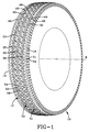
- Fig. 1 is a perspective view of a tread according to the present invention annularly attached to a tire.
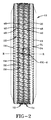
- Fig. 2 is a plan view of the tread illustrated in Fig. 1.
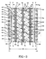
- Fig. 3 is a view illustrating the footprint of the tire.
- Fig. 4 is a cross-sectional view of the tire taken along lines 4-4 of Fig. 3.
- Fig. 5 is an enlarged view of the tread as taken from Fig. 4.
- Fig. 6 is an enlarged view of a block element of the tire.
- the tread 12 is annularly attached to a tire 10.
- the tread when configured annularly, has an axis of rotation R, a pair of lateral edges 14,16 defined by the shoulders of the tread, and an inner tread surface 20.
- the distance between the lateral edges is defined as the tread width (TW).
- rib 30,32 Adjacent each of the lateral edges 14,16 is a rib 30,32.
- the ribs 30,32 extend circumferentially about the axis of rotation R and radially outwardly from the inner tread surface 20.
- the tread has a plurality of lateral extending grooves 40.
- Each lateral groove 40 extends generally axially from rib 30 to rib 32.
- the lateral grooves 40 extend into the two shoulder ribs 30,32 forming a notch 42 in each rib.
- the notch has an axially outer end 46 and a base 44 which is inclined and extends radially above the inner tread surface 20 by at least 10% of the groove depth.
- the illustrated tread 12 has three circumferentially extending zigzag grooves 35,36,37.
- One such groove 35 being centrally located and the second and third such grooves 36,37 being axially spaced within 30% of the tread width (TW) from a lateral edge 14,16.
- the circumferential and lateral grooves 35,36,37,40 cooperate to define block elements 50.
- the block elements 50 are arranged in two circumferential rows 51,52.
- Each block element 50 has a first and second side 54,56 defined by the lateral grooves.
- Each shoulder rib 30,32 includes a plurality of axially extending notches 34 which extend from the lateral edge 14,16 to axially inner ends 31.
- each of the ribs 30,32 include a circumferentially continuous band 33 devoid of lateral grooves having an axial width RW of at least 10% of the tread width TW as measured between a pair of planes perpendicular to the axis of rotation of the tread 12 with one side plane X-X intersecting axially inner ends of the axial innermost lateral edge notches and the other plane Y-Y intersecting the axially outer ends of the axially outermost notches formed by the lateral grooves 40.
- the circumferential zigzag grooves 35,36,37 include a short lateral extending portion 60 about equally spaced between the lateral grooves 40.
- the short lateral portion 60 extends into the ribs 30,32 or the block elements 50.
- Each short lateral portion 60 included a notch 62 at the extremities of the groove.
- Each notch 62 has an axially outermost end 63 and an axially innermost end 64.
- the axially outermost ends 63 in the illustrated embodiment are axially unaligned. Alternatively, the ends of the notches 62 could be axially aligned.
- the circumferentially continuous band 33 would have a width is determined by planes X-X and Y-Y, each plane being perpendicular to the axis of rotation and intersecting the ends of the notches that extend furthest into the rib.
- the ribs as described above may further include a narrow circumferentially continuous groove, known in the art as a decoupling groove 38.
- a decoupling groove 38 could be placed within the continuous band without adversely affecting wear.
- the preferred embodiment does not employ such a decoupling groove.
- the shoulder ribs 30,32 as illustrated exhibit excellent wear characteristics. It is believed that the continuous band 33 being of a width of at least 10% of the tread width TW provides a sufficiently stiff shoulder region having a large amount of tread rubber in contact with the roadway such that the occurrence of irregular wear can be minimized.
- the prior art drive axle tire for trucks either provided block elements in the shoulder or ribs with lateral grooves extending sufficiently into the rib that the rib acted as a block element. The lateral grooves improved the flexibility of the rib while simultaneously weakening the rib such that irregular high-low wear problems were common.
- the present invention permits the rib to maintain stiffness and a high contact surface area. Both features are believed to improve the overall tread wear performance.
- the circumferential grooves 35,36,37 have a depth (d) of at least 19 mm.
- the lateral grooves between the first and second sides 54,56 of the circumferentially adjacent block elements 50 has an average depth of between 75% and 90% of the average depth (d) of the circumferential grooves 35,36,37.
- This reduced depth at the location between the first and second sides creates a tie-bar 48 between the adjacent block elements 50.
- the height of the tie-bar 48 is kept to a minimum in an attempt to insure that the tread block elements 50 maintain their tractive performance throughout the useful life of the tread.
- the shape of the tread pattern is not appreciably altered until the elements are worn to about the level of tie-bar 48.
- the tread grooves 35,36,37 have a depth of at least 22 mm as measured from the inner tread surface radially outwardly.
- stiff shoulder ribs 30,32 and the unique block element shapes with tie bars 48 enables the tread 12 to have these deep grooves.
- This increased groove depth enables the tread to achieve extremely high tread wear mileage.
- drive axle treads have a tread rubber groove depth of less than 26/32 of one inch, or about 20 mm or less.
- the deepness of the tread grooves makes the block elements 50 more flexible or less stiff. This increased flexibility is a limiting factor in how deep the tread may be because flexible tread elements tend to induce uneven tread wear problems.
- the inclination of the elements relative to the direction of travel also had the resultant effect of a loss of tractive performance.
- the tractive forces could be improved.
- Such a design tended to exhibit heel and toe wear and other uneven wear problems.
- the present design as depicted in the figures has block elements 50 that have leading and trailing first and second sides 54,56 that approach a normal or almost perpendicular orientation relative to the direction of travel.
- the average inclination ⁇ of the leading and trailing edges of the tread elements is about between 70° and 85° relative to the direction of travel. This orientation approaches the optimal shape for tractive performance greatly reducing uneven wear problems.
- the use of only two rows of block elements 51,52 enables the blocks 50 to have an average axial width that is greater than 75% of the average circumferential length.
- the block elements each have a surface area which when taken from a footprint of the tire occupies at least 60% of an area defined by a rectangular boundary having two axial and two circumferential extending sides.
- the axially extending sides 80 are parallel to the axis of rotation and the circumferentially extending sides 82 are perpendicular to the axis of rotation.
- the boundary has each side intersecting axial or circumferential extremities of the block element 50 thereby enveloping the element.
- the elements occupy at least 65% of the area defined by the rectangular boundary.
- the tread block elements as illustrated have a circumferential extent as measured between the first and second sides which is in the range of 75% to 125% of the axial extent of the block element.
- the tread pattern of the present invention should have a net-to-gross ratio of at least 55%.
- the illustrated embodiment has a net-to-gross ratio of above 65%. This higher percentage of rubber contacting the road is believed to contribute to improve overall tread wear.
- the central circumferential zigzag groove 35 has a width of greater than 5% of the tread width TW.
- the central groove 35 preferably has a width of 7% of the tread width while the second and third circumferential grooves 36,37 have a width of less than 90% of the width of the central groove, preferably less than 85%.
- This facilitates designing the tread with a zigzag amplitude greater at the central groove than at the shoulder grooves 36,37. It is believed that the irregular wear problems are more prone to occur near the shoulders than in the central region of the tread and therefore, the higher zigzag amplitude can be tolerated in that central region.
- the zigzag amplitude be at least 10% greater in the central groove 35 than in the second and third circumferential grooves 36 and 37.
- the zigzag amplitude as used herein refers to the lateral extending displacement of the centerline of the circumferentially extending grooves.
- the ribs 30,32 have a minimum cross section width of not less than 10.0% of the tread width TW as measured in any radial plane. The 10.0% minimum width is measured in any direction along the rib surface. In the event an optional narrow decoupling groove 38 is added to the rib 30,32, it should be ignored for purposes of measuring the minimum rib width.
- the lateral grooves 40 have an average depth equal to the depth of the circumferential grooves 35,36,37 at the intersections of these grooves.
- a plurality of projections 70 are located in the bottoms of the lateral and circumferential grooves 40,35,36,37. These projections 70 help reduce the occurrence of trapping stones between the deep groove walls and also assist in preventing the stone from drilling through the inner tread surface 20 and exposing the reinforcing cords of the tire to damage.
- a limited amount of siping 90 may be employed in the tread ribs 30,32 and block elements 50.
- the sipes 90 provide additional edges to assist in traction performance and reduce or delay the initiation of erosion type wear on protruding elements.
- the siping 90 adjacent the circumferential grooves 35,36,37 follows a path parallel to these grooves.
- the sipes 90 that laterally extend within the block elements 50 follow a path generally parallel to the lateral grooves 40.
- Tires employing a tread pattern according to the present invention were tested under normal drive axle loading conditions. The tires were tested for occurrence of uneven wear and for tread wear mileage performance. After 181,667 miles, the left front drive axle inside position tire exhibited some minor yet noticeable right shoulder wear. After 171,659 miles, the outside position tire was extremely uniform with no signs of irregular wear.
- the absence of irregular wear in the present tire combined with the preferred deep nonskid tread means that the tire may be capable of in excess of 200,000 miles of tread wear life.
- a tread made according to the present invention can improve the overall treadwear performance compared to commercially available treads for drive axle use on commercial trucks.
- tread rubber compound may be altered to permit extended mileage without employing the preferred 22 mm nonskid depth.
- Conventional truck tire rubber compounds employing a tread pattern according to the present invention should preferably employ the deeper nonskid to achieve maximum mileage.
- the design as described above could permit alternative rubber compounds to be employed that have particularly excellent wear characteristics without a significant concern for uneven wear or traction problems due to the unique combination of the ribs and the block element's shape and orientation.
Landscapes
- Engineering & Computer Science (AREA)
- Mechanical Engineering (AREA)
- Tires In General (AREA)
Applications Claiming Priority (2)
| Application Number | Priority Date | Filing Date | Title |
|---|---|---|---|
| US07/976,860 US5361815A (en) | 1992-11-16 | 1992-11-16 | Tread for a tire with blocks and ribs |
| US976860 | 1992-11-16 |
Publications (2)
| Publication Number | Publication Date |
|---|---|
| EP0598300A1 true EP0598300A1 (de) | 1994-05-25 |
| EP0598300B1 EP0598300B1 (de) | 1997-04-23 |
Family
ID=25524557
Family Applications (1)
| Application Number | Title | Priority Date | Filing Date |
|---|---|---|---|
| EP93118067A Expired - Lifetime EP0598300B1 (de) | 1992-11-16 | 1993-11-08 | Reifenlauffläche |
Country Status (10)
| Country | Link |
|---|---|
| US (1) | US5361815A (de) |
| EP (1) | EP0598300B1 (de) |
| AU (1) | AU669010B2 (de) |
| BR (1) | BR9304669A (de) |
| CA (1) | CA2088303C (de) |
| DE (1) | DE69310100T2 (de) |
| ES (1) | ES2102579T3 (de) |
| MX (1) | MX9306872A (de) |
| MY (1) | MY113696A (de) |
| TR (1) | TR28130A (de) |
Cited By (6)
| Publication number | Priority date | Publication date | Assignee | Title |
|---|---|---|---|---|
| EP0855291A2 (de) * | 1997-01-25 | 1998-07-29 | Continental Aktiengesellschaft | Profil für PKW-Luftreifen |
| WO2000026040A1 (en) * | 1998-10-30 | 2000-05-11 | Pirelli Pneumatici S.P.A. | Motor vehicle tyre, particularly for lorries and the like |
| US6736175B2 (en) | 1998-10-30 | 2004-05-18 | Pirelli Pneumatici S.P.A. | Motor vehicle tire, particularly for lorries and the like |
| WO2007055065A1 (ja) | 2005-11-09 | 2007-05-18 | The Yokohama Rubber Co., Ltd. | 空気入りタイヤ |
| EP2990235A1 (de) * | 2014-08-27 | 2016-03-02 | Continental Reifen Deutschland GmbH | Fahrzeugluftreifen |
| CN108202565A (zh) * | 2016-12-19 | 2018-06-26 | 诺基安伦卡特股份有限公司 | 充气轮胎,胎面带,及包含刀槽花纹的胎面块,及制造刀槽花纹的薄层板 |
Families Citing this family (37)
| Publication number | Priority date | Publication date | Assignee | Title |
|---|---|---|---|---|
| USD384011S (en) * | 1995-05-23 | 1997-09-23 | The Yokohama Rubber Co., Ltd. | Automobile tire |
| US6176284B1 (en) * | 1996-07-19 | 2001-01-23 | Sumitomo Rubber Industries, Ltd. | Pneumatic tire |
| US6000451A (en) * | 1996-07-19 | 1999-12-14 | Sumitomo Rubber Industries, Ltd. | Pneumatic tire including at least one projection |
| DE69722728T2 (de) * | 1996-08-05 | 2003-12-04 | Sumitomo Rubber Industries Ltd., Kobe | Luftreifen |
| USD388369S (en) * | 1996-08-15 | 1997-12-30 | The Goodyear Tire & Rubber Company | Tire tread |
| JP3507634B2 (ja) * | 1996-10-01 | 2004-03-15 | 住友ゴム工業株式会社 | 空気入りタイヤ |
| JP3515296B2 (ja) * | 1996-10-28 | 2004-04-05 | 横浜ゴム株式会社 | 重荷重用空気入りタイヤ |
| IT1287154B1 (it) | 1996-11-12 | 1998-08-04 | Pirelli | Fascia battistrada di pneumatico,particolarmente per autoveicoli fuoristrada |
| USD432960S (en) * | 1998-11-12 | 2000-10-31 | The Goodyear Tire & Rubber Company | Tire tread |
| USD425457S (en) * | 1999-04-20 | 2000-05-23 | The Goodyear Tire & Rubber Company | Tire tread |
| BR0100126A (pt) * | 2000-02-01 | 2001-08-28 | Goodyear Tire & Rubber | Pneu radial com linha de lona aperfeiçoada |
| DE602005020773D1 (de) * | 2004-05-27 | 2010-06-02 | Bridgestone Corp | Luftreifen |
| JP5311841B2 (ja) * | 2008-02-19 | 2013-10-09 | 株式会社ブリヂストン | 空気入りタイヤ |
| US9033013B2 (en) * | 2008-06-06 | 2015-05-19 | Continental Tire North America, Inc. | Undercut stone bumper structure for vehicle tire groove |
| US20100236681A1 (en) * | 2009-03-17 | 2010-09-23 | Daniel Ray Beha | Tire having tread blocks with blended walls |
| US20110265926A1 (en) * | 2010-04-28 | 2011-11-03 | Societe De Technologie Michelin | Tire tread for preventing irregular wear |
| US9616716B2 (en) | 2011-12-14 | 2017-04-11 | Bridgestone Americas Tire Operations, Llc | Three dimensional sipe |
| JP6135070B2 (ja) * | 2012-08-22 | 2017-05-31 | 横浜ゴム株式会社 | 空気入りタイヤ |
| JP5722932B2 (ja) * | 2013-02-01 | 2015-05-27 | 株式会社ブリヂストン | 空気入りタイヤ |
| JP6013979B2 (ja) * | 2013-06-13 | 2016-10-25 | 住友ゴム工業株式会社 | 空気入りタイヤ |
| USD739815S1 (en) * | 2013-07-30 | 2015-09-29 | Hankook Tire Co. Ltd. | Tire tread |
| JP1496209S (de) * | 2013-08-28 | 2015-07-21 | ||
| JP5932761B2 (ja) * | 2013-12-18 | 2016-06-08 | 住友ゴム工業株式会社 | 空気入りタイヤ |
| JP2017501082A (ja) | 2013-12-26 | 2017-01-12 | ブリヂストン アメリカズ タイヤ オペレーションズ、 エルエルシー | 可撓性ゲート装置を有するタイヤトレッド |
| JP6366525B2 (ja) * | 2015-02-27 | 2018-08-01 | 東洋ゴム工業株式会社 | 空気入りタイヤ |
| WO2016204719A1 (en) * | 2015-06-15 | 2016-12-22 | Bridgestone Americas Tire Operations, Llc | Conductive splicing cement |
| EP3176006B1 (de) * | 2015-11-24 | 2018-06-20 | Sumitomo Rubber Industries Limited | Reifen |
| NZ747566A (en) * | 2016-04-26 | 2020-06-26 | American Pacific Ind Inc | Tire with unique tread block and up sidewall designs |
| DE102016211108A1 (de) * | 2016-06-22 | 2017-12-28 | Continental Reifen Deutschland Gmbh | Fahrzeugluftreifen |
| JP6781578B2 (ja) * | 2016-06-30 | 2020-11-04 | Toyo Tire株式会社 | 空気入りタイヤ |
| JP6682386B2 (ja) * | 2016-06-30 | 2020-04-15 | Toyo Tire株式会社 | 空気入りタイヤ |
| JP6763705B2 (ja) * | 2016-06-30 | 2020-09-30 | Toyo Tire株式会社 | 空気入りタイヤ |
| EP3323637B1 (de) * | 2016-11-22 | 2019-09-04 | Sumitomo Rubber Industries, Ltd. | Reifen |
| JP6946851B2 (ja) * | 2017-08-18 | 2021-10-13 | 住友ゴム工業株式会社 | タイヤ |
| JP6965671B2 (ja) * | 2017-10-03 | 2021-11-10 | 住友ゴム工業株式会社 | タイヤ |
| JP7000836B2 (ja) * | 2017-12-15 | 2022-01-19 | 住友ゴム工業株式会社 | タイヤ |
| JP7156337B2 (ja) * | 2020-06-16 | 2022-10-19 | 住友ゴム工業株式会社 | タイヤ |
Citations (6)
| Publication number | Priority date | Publication date | Assignee | Title |
|---|---|---|---|---|
| GB2003804A (en) * | 1977-09-01 | 1979-03-21 | Bridgestone Tire Co Ltd | Pneumatic tyre for heavy duty vehicles |
| EP0233135A2 (de) * | 1986-01-29 | 1987-08-19 | The Goodyear Tire & Rubber Company | Ganzjahres-Luftreifen mit abgeschliffenen Blöcken |
| EP0348335A2 (de) * | 1988-06-20 | 1989-12-27 | The Goodyear Tire & Rubber Company | Reifenlaufflächen und Reifen |
| EP0413502A1 (de) * | 1989-08-08 | 1991-02-20 | Bridgestone Corporation | Luftreifen für LKW |
| EP0468815A1 (de) * | 1990-07-27 | 1992-01-29 | Bridgestone Corporation | Luftreifen |
| EP0477542A2 (de) * | 1990-09-04 | 1992-04-01 | The Goodyear Tire & Rubber Company | Luftreifen |
Family Cites Families (6)
| Publication number | Priority date | Publication date | Assignee | Title |
|---|---|---|---|---|
| BE790875A (fr) * | 1971-11-08 | 1973-05-03 | Michelin & Cie | Perfectionnements aux enveloppes de pneumatiques |
| JPS60189607A (ja) * | 1984-03-09 | 1985-09-27 | Yokohama Rubber Co Ltd:The | 空気入りラジアルタイヤ |
| US4807679A (en) * | 1987-06-11 | 1989-02-28 | The Goodyear Tire & Rubber Company | Pneumatic tire tread having sipes |
| JP2738549B2 (ja) * | 1988-11-15 | 1998-04-08 | 株式会社ブリヂストン | 重荷重用空気入りラジアルタイヤ |
| JPH0392402A (ja) * | 1989-09-06 | 1991-04-17 | Bridgestone Corp | 空気入りタイヤ |
| US5085259A (en) * | 1990-07-16 | 1992-02-04 | The Goodyear Tire & Rubber Company | Tire tread |
-
1992
- 1992-11-16 US US07/976,860 patent/US5361815A/en not_active Expired - Fee Related
-
1993
- 1993-01-28 CA CA002088303A patent/CA2088303C/en not_active Expired - Fee Related
- 1993-11-02 TR TR01005/93A patent/TR28130A/xx unknown
- 1993-11-03 MY MYPI93002301A patent/MY113696A/en unknown
- 1993-11-04 MX MX9306872A patent/MX9306872A/es not_active IP Right Cessation
- 1993-11-08 ES ES93118067T patent/ES2102579T3/es not_active Expired - Lifetime
- 1993-11-08 DE DE69310100T patent/DE69310100T2/de not_active Expired - Fee Related
- 1993-11-08 EP EP93118067A patent/EP0598300B1/de not_active Expired - Lifetime
- 1993-11-09 BR BR9304669A patent/BR9304669A/pt not_active IP Right Cessation
- 1993-11-15 AU AU50698/93A patent/AU669010B2/en not_active Ceased
Patent Citations (7)
| Publication number | Priority date | Publication date | Assignee | Title |
|---|---|---|---|---|
| GB2003804A (en) * | 1977-09-01 | 1979-03-21 | Bridgestone Tire Co Ltd | Pneumatic tyre for heavy duty vehicles |
| US4223712A (en) * | 1977-09-01 | 1980-09-23 | Bridgestone Tire Company, Limited | Pneumatic tire for heavy duty vehicles |
| EP0233135A2 (de) * | 1986-01-29 | 1987-08-19 | The Goodyear Tire & Rubber Company | Ganzjahres-Luftreifen mit abgeschliffenen Blöcken |
| EP0348335A2 (de) * | 1988-06-20 | 1989-12-27 | The Goodyear Tire & Rubber Company | Reifenlaufflächen und Reifen |
| EP0413502A1 (de) * | 1989-08-08 | 1991-02-20 | Bridgestone Corporation | Luftreifen für LKW |
| EP0468815A1 (de) * | 1990-07-27 | 1992-01-29 | Bridgestone Corporation | Luftreifen |
| EP0477542A2 (de) * | 1990-09-04 | 1992-04-01 | The Goodyear Tire & Rubber Company | Luftreifen |
Cited By (13)
| Publication number | Priority date | Publication date | Assignee | Title |
|---|---|---|---|---|
| EP0855291A2 (de) * | 1997-01-25 | 1998-07-29 | Continental Aktiengesellschaft | Profil für PKW-Luftreifen |
| EP0855291A3 (de) * | 1997-01-25 | 2000-05-10 | Continental Aktiengesellschaft | Profil für PKW-Luftreifen |
| KR100839139B1 (ko) * | 1998-10-30 | 2008-06-19 | 피렐리 타이어 소시에떼 퍼 아찌오니 | 특히 화물차 및 화물차와 유사한 차량용 원동 차량 타이어 |
| US6736175B2 (en) | 1998-10-30 | 2004-05-18 | Pirelli Pneumatici S.P.A. | Motor vehicle tire, particularly for lorries and the like |
| WO2000026040A1 (en) * | 1998-10-30 | 2000-05-11 | Pirelli Pneumatici S.P.A. | Motor vehicle tyre, particularly for lorries and the like |
| WO2007055065A1 (ja) | 2005-11-09 | 2007-05-18 | The Yokohama Rubber Co., Ltd. | 空気入りタイヤ |
| JP2007131106A (ja) * | 2005-11-09 | 2007-05-31 | Yokohama Rubber Co Ltd:The | 空気入りタイヤ |
| EP1946941A1 (de) * | 2005-11-09 | 2008-07-23 | The Yokohama Rubber Co., Ltd. | Luftreifen |
| EP1946941A4 (de) * | 2005-11-09 | 2009-12-02 | Yokohama Rubber Co Ltd | Luftreifen |
| JP4730063B2 (ja) * | 2005-11-09 | 2011-07-20 | 横浜ゴム株式会社 | 空気入りタイヤ |
| EP2990235A1 (de) * | 2014-08-27 | 2016-03-02 | Continental Reifen Deutschland GmbH | Fahrzeugluftreifen |
| CN108202565A (zh) * | 2016-12-19 | 2018-06-26 | 诺基安伦卡特股份有限公司 | 充气轮胎,胎面带,及包含刀槽花纹的胎面块,及制造刀槽花纹的薄层板 |
| CN108202565B (zh) * | 2016-12-19 | 2021-10-15 | 诺基安伦卡特股份有限公司 | 充气轮胎,胎面带,及包含刀槽花纹的胎面块,及制造刀槽花纹的薄层板 |
Also Published As
| Publication number | Publication date |
|---|---|
| AU5069893A (en) | 1994-05-26 |
| AU669010B2 (en) | 1996-05-23 |
| MX9306872A (es) | 1994-05-31 |
| BR9304669A (pt) | 1994-05-24 |
| EP0598300B1 (de) | 1997-04-23 |
| TR28130A (tr) | 1996-02-13 |
| DE69310100T2 (de) | 1997-10-09 |
| DE69310100D1 (de) | 1997-05-28 |
| CA2088303A1 (en) | 1994-05-17 |
| ES2102579T3 (es) | 1997-08-01 |
| MY113696A (en) | 2002-05-31 |
| CA2088303C (en) | 2003-11-25 |
| US5361815A (en) | 1994-11-08 |
Similar Documents
| Publication | Publication Date | Title |
|---|---|---|
| EP0598300B1 (de) | Reifenlauffläche | |
| US6116309A (en) | Tread for a tire including five rib parts | |
| US6142200A (en) | Truck steer tire tread including circumferential grooves | |
| US6481480B1 (en) | Convertible tread for a radial truck or trailer tire | |
| EP0485883B1 (de) | Lauffläche für Winterreifen | |
| EP0456949B1 (de) | Lauffläche für Luftreifen | |
| EP0678402B1 (de) | Lauffläche für Reifen | |
| US4934424A (en) | Pneumatic tire having blocks with plural transverse sipes at different depths | |
| EP0205233B1 (de) | Luftreifen | |
| US6000450A (en) | Studless tire | |
| EP0904960B1 (de) | Spikeloser luftreifen | |
| EP0342908B1 (de) | Luftreifen | |
| EP0313361A2 (de) | Luftreifen für LKW ohne unregelmässige Abnutzung | |
| EP0715973B1 (de) | Luftreifen für vereiste/verschneite Böden | |
| GB2120183A (en) | Pneumatic radial tire tread | |
| KR20030084954A (ko) | 특히 눈 덮인 지면용의 차량용 광폭 트레드 타이어 | |
| EP0912355B1 (de) | Eine umwandelbare lauffläche für lkw-reifen oder anhängerreifen | |
| JP4262817B2 (ja) | 空気入りタイヤ | |
| EP0194069A2 (de) | Fahrzeugrad und radialer Luftreifen | |
| EP1363789B1 (de) | Laufrichtungsgebundenes laufflächenprofil für einen winterreifen | |
| JPS626802A (ja) | ウエツト性に優れた空気入りタイヤ | |
| US6102093A (en) | Pneumatic tire including long blocks and wide blocks | |
| EP1093939B1 (de) | Reifenlauffläche für Strassen/geländegängige Fahrzeuge | |
| JP4441009B2 (ja) | 空気入りタイヤ | |
| JPH05178015A (ja) | 重荷重用空気入りラジアルタイヤ |
Legal Events
| Date | Code | Title | Description |
|---|---|---|---|
| PUAI | Public reference made under article 153(3) epc to a published international application that has entered the european phase |
Free format text: ORIGINAL CODE: 0009012 |
|
| 17P | Request for examination filed |
Effective date: 19931108 |
|
| AK | Designated contracting states |
Kind code of ref document: A1 Designated state(s): DE ES FR GB IT |
|
| 17Q | First examination report despatched |
Effective date: 19951123 |
|
| GRAG | Despatch of communication of intention to grant |
Free format text: ORIGINAL CODE: EPIDOS AGRA |
|
| GRAH | Despatch of communication of intention to grant a patent |
Free format text: ORIGINAL CODE: EPIDOS IGRA |
|
| GRAH | Despatch of communication of intention to grant a patent |
Free format text: ORIGINAL CODE: EPIDOS IGRA |
|
| GRAA | (expected) grant |
Free format text: ORIGINAL CODE: 0009210 |
|
| AK | Designated contracting states |
Kind code of ref document: B1 Designated state(s): DE ES FR GB IT |
|
| REF | Corresponds to: |
Ref document number: 69310100 Country of ref document: DE Date of ref document: 19970528 |
|
| ET | Fr: translation filed | ||
| REG | Reference to a national code |
Ref country code: ES Ref legal event code: FG2A Ref document number: 2102579 Country of ref document: ES Kind code of ref document: T3 |
|
| PLBE | No opposition filed within time limit |
Free format text: ORIGINAL CODE: 0009261 |
|
| STAA | Information on the status of an ep patent application or granted ep patent |
Free format text: STATUS: NO OPPOSITION FILED WITHIN TIME LIMIT |
|
| 26N | No opposition filed | ||
| REG | Reference to a national code |
Ref country code: GB Ref legal event code: IF02 |
|
| PGFP | Annual fee paid to national office [announced via postgrant information from national office to epo] |
Ref country code: GB Payment date: 20021002 Year of fee payment: 10 |
|
| PGFP | Annual fee paid to national office [announced via postgrant information from national office to epo] |
Ref country code: FR Payment date: 20021105 Year of fee payment: 10 |
|
| PGFP | Annual fee paid to national office [announced via postgrant information from national office to epo] |
Ref country code: ES Payment date: 20021120 Year of fee payment: 10 |
|
| PGFP | Annual fee paid to national office [announced via postgrant information from national office to epo] |
Ref country code: DE Payment date: 20021127 Year of fee payment: 10 |
|
| PG25 | Lapsed in a contracting state [announced via postgrant information from national office to epo] |
Ref country code: GB Free format text: LAPSE BECAUSE OF NON-PAYMENT OF DUE FEES Effective date: 20031108 |
|
| PG25 | Lapsed in a contracting state [announced via postgrant information from national office to epo] |
Ref country code: ES Free format text: LAPSE BECAUSE OF NON-PAYMENT OF DUE FEES Effective date: 20031110 |
|
| PG25 | Lapsed in a contracting state [announced via postgrant information from national office to epo] |
Ref country code: DE Free format text: LAPSE BECAUSE OF NON-PAYMENT OF DUE FEES Effective date: 20040602 |
|
| GBPC | Gb: european patent ceased through non-payment of renewal fee |
Effective date: 20031108 |
|
| PG25 | Lapsed in a contracting state [announced via postgrant information from national office to epo] |
Ref country code: FR Free format text: LAPSE BECAUSE OF NON-PAYMENT OF DUE FEES Effective date: 20040730 |
|
| REG | Reference to a national code |
Ref country code: FR Ref legal event code: ST |
|
| REG | Reference to a national code |
Ref country code: ES Ref legal event code: FD2A Effective date: 20031110 |
|
| PG25 | Lapsed in a contracting state [announced via postgrant information from national office to epo] |
Ref country code: IT Free format text: LAPSE BECAUSE OF NON-PAYMENT OF DUE FEES;WARNING: LAPSES OF ITALIAN PATENTS WITH EFFECTIVE DATE BEFORE 2007 MAY HAVE OCCURRED AT ANY TIME BEFORE 2007. THE CORRECT EFFECTIVE DATE MAY BE DIFFERENT FROM THE ONE RECORDED. Effective date: 20051108 |