EP0597093A1 - Verfahren und vorrichtung zur herstellung von metallstäben - Google Patents
Verfahren und vorrichtung zur herstellung von metallstäben Download PDFInfo
- Publication number
- EP0597093A1 EP0597093A1 EP91916223A EP91916223A EP0597093A1 EP 0597093 A1 EP0597093 A1 EP 0597093A1 EP 91916223 A EP91916223 A EP 91916223A EP 91916223 A EP91916223 A EP 91916223A EP 0597093 A1 EP0597093 A1 EP 0597093A1
- Authority
- EP
- European Patent Office
- Prior art keywords
- strands
- pair
- cut
- slit rolls
- rolls
- Prior art date
- Legal status (The legal status is an assumption and is not a legal conclusion. Google has not performed a legal analysis and makes no representation as to the accuracy of the status listed.)
- Granted
Links
Images






Classifications
-
- B—PERFORMING OPERATIONS; TRANSPORTING
- B21—MECHANICAL METAL-WORKING WITHOUT ESSENTIALLY REMOVING MATERIAL; PUNCHING METAL
- B21B—ROLLING OF METAL
- B21B1/00—Metal-rolling methods or mills for making semi-finished products of solid or profiled cross-section; Sequence of operations in milling trains; Layout of rolling-mill plant, e.g. grouping of stands; Succession of passes or of sectional pass alternations
- B21B1/08—Metal-rolling methods or mills for making semi-finished products of solid or profiled cross-section; Sequence of operations in milling trains; Layout of rolling-mill plant, e.g. grouping of stands; Succession of passes or of sectional pass alternations for rolling structural sections, i.e. work of special cross-section, e.g. angle steel
- B21B1/0815—Metal-rolling methods or mills for making semi-finished products of solid or profiled cross-section; Sequence of operations in milling trains; Layout of rolling-mill plant, e.g. grouping of stands; Succession of passes or of sectional pass alternations for rolling structural sections, i.e. work of special cross-section, e.g. angle steel from flat-rolled products, e.g. by longitudinal shearing
Definitions
- the present invention relates to methods and apparatuses for producing metal bars wherein at least four strands of metal bars, particularly steel bars, are obtained by simultaneously rolling from a single billet.
- a steel bar of 9 to 20 mm in diameter as a concrete bar for reinforcing concrete is produced in large quantities.
- the bar includes not only a bar whose cross section is substantially round, but also a bar whose cross section is slightly oval or square-shaped and a ribbed bar which is the above-mentioned bar, on which ribs are formed.
- Said bars are produced by a bar rolling mill generally having 16 to 20 stands in the following manner:
- a finishing rolling train is composed of 4 stands K 4 , K 3 , K 2 , and Ki.
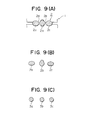
- the K 4 and K 3 stands roll a preformed billet to produce three strands of bars 2a, 2b and 2c connected to each other by means of thin connecting portions 2d and 2e as shown in Figure 9 (A).
- a pair of slit rolls cuts the three strands of bars 2a, 2b and 2c along the connecting portions, and then K 2 stand, composed of a pair of calibered rolls, rolls the three cut strands of bars 2a, 2b and 2c to produce bars of oval cross section as shown in Figure 9(B), and the K 1 stand, composed of a pair of rolls with a finishing caliber (a bore type), rolls the three strands to produce final product bars 3a, 3b, and 3c as shown in Figure 9(C).
- Figure 9(A) shows a state of rolling a billet at the stand K 3 .
- Figure 9(B) shows a state of strands having been cut off by means of a pair of slit rolls, following the K 2 stand.
- Figure 9(C) shows the shapes of bars 3a, 3b and 3c after the bars have been rolled at the stand K i .
- the "Prior Art 1" is limited to simultaneously producing three strands of bars from a single preformed billet by means of such a finishing rolling train.
- the present invention provides a method for producing metal bars, which solves said problems and is further improved, and it is an object of the present invention to provide a method for simultaneously producing at least four metal bars and an apparatus therefor.
- the present invention proposes a new construction of a finishing rolling train and a new rolling method for producing metal bars wherein the conventional roughing rolling train is used.
- the stands of a finishing rolling train are stands K 4 , K 3 , K 2 and K 1 arranged in series in the rolling direction.
- reference numeral 9 denotes a final stand K 5 in a roughing rolling train.
- the final stand has a pair of vertical rolls (hereafter referred to as "V roll") and finally controls the shape of a preformed billet supplied to the next stand K 4 .
- Reference numeral 11 denotes a stand K 4 , 13 a stand K 3 16 a first pair of slit rolls, 17 a second pair of slit rolls, 18 a stand K 2 and 20 a stand K i .
- An ordinary roughing rolling train (not shown) is arranged before the stand Ks.
- a finishing billet yard is laid out, which includes cutting devices and cooling beds. Roll calibers arranged in the stands as shown in Figure 1 and a process of deformation of strands are described with specific reference to Figure 2.
- Figure 2(A) shows a shape of a roll caliber of said stand K 5 and a shape of a preformed billet 10.
- the stand K 5 provides a shape of the preformed billet 10 by means of a pair of V rolls required for rolling in the stand K 4 .
- FIG 2(B) shows an oval caliber rolls 11 and the strands divided into four in the case of simultaneously rolling four strands.
- the caliber roll 11 has three convex portions 11 a, 11 b and 11 c as shown in Figure 2(B) and divides the preformed billet 10 into four strands 12a through 12d having a substantially equal cross sectional area.
- the depth of the convex portions is from 1 to 4 mm, and the four strands are sufficiently connected to each other with shallow cleavages.
- the depth of the cleavages is from 10 to 20 % of the thickness of the strand 12.
- the four strands divided are substantially square-shaped or oval in shape.
- Figure 2(C) shows that the connected four strands are further rolled by the stand K 3 .
- Both the outer roll calibers 13a and 13d are of oval shape or box-shaped and the roll calibers 13b and 13c at the intermediate portion are diamond-shaped in principle. Accordingly, both the outer strands 14a and 14d are box-shaped and the two strands 14b and 14c at the intermediate portion are diamond-shaped.
- the four strands are connected to each other by means of thin connecting portions (hereinafter referred to as the "connecting portion") 14e through 14g.
- Figure 2(D) shows that the connecting portions 14e and 14g of the connecting portions are cut by means of a first pair of slit rolls.
- Figure 2(E) shows the four strands 14a through 14d after the center connecting portion 14f has been cut by means of a second pair of slit rolls.
- Figure 2(F) shows roll calibers 18a through 18d and strands 19a through 19d in the stand K 2 .
- the stand K 2 has oval roll calibers so that the four strands as shown in Figure 2(E) are rolled to be adapted to the final rolling, whereby four strands 19a to 19d of oval shape are formed.
- Figure 2(G) shows roll calibers 20a through 20d on the stand K 1 for carrying out the final rolling.
- the roll caliber is a round caliber.
- the roll calibers in the stand K 1 are required to have the shape of the final product.
- the roll caliber should be a caliber which gives ribs on the bars.
- Approximate dimensions of the preformed billet are shown to show specific examples of the present invention.
- a square billet of 150 mm in each side was rolled by means of a roughing rolling train.
- a preformed billet 10 obtained in the final stand K 5 had a box-shape with a breadth of 41.24 mm and a thickness of 13.48 mm and the central portion of the preformed billet was swelling. Accordingly, the roll calibers also were box-shaped.
- a roll caliber in the stand K 4 had a breadth of approximately 48.1 mm and had an oval shape as a whole, the maximum thickness of which was about 10.5 mm.
- the roll caliber had convex portions 11 a through 11 at positions where the roll caliber was divided into about four equal portions.
- the breadth of each of the divided strands was from 11.5 to 12.5 mm.
- Each of both the outer roll calibers 13a and 13d in the stand K 3 had a breadth of about 7.9 mm and a thickness of 9.5 mm and had an oval shape.
- Diamond-shaped roll calibers 13b and 13c at the intermediate portion had a breadth of about 11.4 mm and a thickness of 12 mm.
- the connecting portions had a breadth of about 0.8 mm and a thickness of 1 mm or less.
- Roll calibers 18a through 18d in the stand K 2 had a breadth of 17.8 mm and a thickness of 6.6 mm and were flat oval- shaped.
- Roll calibers 20a through 20d in the stand K 1 were round calibers of about 8.9 mm in diameter. In consequence, a bar of about 8.8 mm in diameter as a final product could be produced.
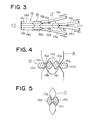
- Figure 3 is a top plan view showing an arrangement of a first pair of slit rolls 16 and a second pair of slit rolls 17 placed just behind a stand K 3 .
- Reference numerals 16c, 16d and 17b denote guides for controlling the directions of movement of cut strands.
- the strands 14a through 14d are cut off as shown in Figure 4.
- the present invention is characterized in that connecting portions of two strands 14a and 14d on the outer sides out of divided four strands 14a through 14d are cut off by means of two edges 16a and 16b of a first pair of slit rolls 16.
- the important points in the shape of the two edges 16a and 16b consist in that the edges are formed so that the cut strands 14a and 14d can be directed outwardly, as shown by the arrows in Figure 3.
- the two central strands 14b and 14c are cut off along the connecting portion 14f by means of the edge 17a of the second pair of slit rolls 17 as shown in Figure 5.
- the angle of the edge 17a of the second pair of slit rolls is formed so that the cut strand can be directed outwardly.
- the present invention is characterized in that initially both the outer strands are cut off and then two inside strands are sequentially cut off, in contrast to the Prior Art 2.
- a method is adopted wherein the strands are sequentially cut off from both the outer strands to the central portion thereof.
- This method has an advantage in that the position of the second pair of slit rolls 17 can be fixed in relation to the position of the first pair of slit rolls 16 independent of the rolling speed of the strands and that the cutting of the strands can be performed to change of the rolling speed and the like.
- the first pair of slit rolls 16 and the second pair of slit rolls 17 are accommodated into a housing 22.
- Reference numeral 23 denotes a guide for leading cut strands.
- the device as a whole is referred to as a slit roll guide.
- Figure 7 shows an embodiment wherein five bars are simultaneously produced.
- Figure 8 shows an embodiment wherein six bars are simultaneously produced.
- the method for simultaneously producing five bars or six bars is quite the same as the method for simultaneously producing four bars. However, additional explanation is given below as follows:
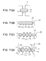
- Figure 7(A) shows a roll caliber 9a in a stand K 5 and a preformed billet 10.
- Figure 7(B) shows a process in which five strands 25a through 25e, each having equal cross sectional area, are rolled by means of a pair of rolls 24 in the stand K 4 .
- Figure 7(C) shows a process in which both the outer strands 27a and 27e are rolled to form strands of oval shape or of a box-shape, and intermediate three strands 27b through 27d are rolled to form strands of a diamond shape or oval shape which is longer in vertical directions, by means of a pair of rolls 26 in the stand K 3 .
- Figure 7(D) shows a process in which both the outer two strands 27a and 27e are cut off by means of two edges 28a and 28b of the first pair of slit rolls 28.
- Figure 7(E) shows a process in which connected three strands 27b, 27c and 27d are cut off by means of the second pair of slip rolls 29 having two edges 29a and 29b along the connecting portions 27g and 27h.
- Figures 7(F) to 7(H) show a process in which the cut strands 27a through 27e are rolled on the stands K 2 and Ki.
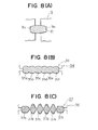
- Figures 8(A) to 8(1) show roll calibers and deformation of the strands when six bars are simultaneously produced.
- Figure 8(A) shows the deformation of the billet in the stand K 5
- Figure 8(B) shows the deformation of the strands in the stand K 4
- Figure 8(C) shows the deformation of the strands in the stand K 3 .
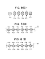
- Figure 8(D) shows a cutting procedure of the strands by means of the first pair of slit rolls 38.
- Figure 8(E) shows a cutting procedure of the strands by means of the second pair of slit rolls 39.
- Figure 8(F) shows a cutting procedure of the strands by means of the third pair slit rolls 40.
- N If the number of bars to be simultaneously produced is N (N 4), 1/2 x N pairs of slit rolls are provided in the slit roll guide when N is an even number. When N is an odd number, 1/2 x (N - 1) pairs of slit rolls are provided in the slit roll guide.
- Figure 8(H) shows a rolling process at the stand K 2 .
- Figure 8(1) shows a rolling process at the stand Ki.
- the present invention is intended to simultaneously roll mainly four steel bars or more. It is clear that the present invention can be applied to the production of aluminium bars, copper bars and other metal bars in general.
Landscapes
- Engineering & Computer Science (AREA)
- Mechanical Engineering (AREA)
- Metal Rolling (AREA)
- Shearing Machines (AREA)
- Reduction Rolling/Reduction Stand/Operation Of Reduction Machine (AREA)
- Wire Processing (AREA)
Applications Claiming Priority (3)
| Application Number | Priority Date | Filing Date | Title |
|---|---|---|---|
| JP2218329A JP2590598B2 (ja) | 1990-08-20 | 1990-08-20 | 1つのビレットから少なくとも4本の金属丸棒を同時に製造するための方法および装置 |
| CA002071545A CA2071545C (en) | 1990-08-20 | 1991-09-21 | Method and apparatus for producing metal bars |
| PCT/JP1991/001263 WO1993005897A1 (en) | 1990-08-20 | 1991-09-21 | Method of manufacturing metal bars and apparatus therefor |
Publications (3)
| Publication Number | Publication Date |
|---|---|
| EP0597093A4 EP0597093A4 (de) | 1994-03-24 |
| EP0597093A1 true EP0597093A1 (de) | 1994-05-18 |
| EP0597093B1 EP0597093B1 (de) | 1997-12-10 |
Family
ID=27169105
Family Applications (1)
| Application Number | Title | Priority Date | Filing Date |
|---|---|---|---|
| EP91916223A Revoked EP0597093B1 (de) | 1990-08-20 | 1991-09-21 | Verfahren und vorrichtung zur herstellung von metallstäben |
Country Status (6)
| Country | Link |
|---|---|
| EP (1) | EP0597093B1 (de) |
| JP (1) | JP2590598B2 (de) |
| CA (1) | CA2071545C (de) |
| DE (1) | DE69128432T2 (de) |
| ES (1) | ES2111575T3 (de) |
| WO (1) | WO1993005897A1 (de) |
Cited By (3)
| Publication number | Priority date | Publication date | Assignee | Title |
|---|---|---|---|---|
| EP0612274A4 (de) * | 1991-11-04 | 1995-01-25 | Structural Metals Inc | Verfahren und vorrichtung zum gleichzeitigen formen von vier rundprofilen aus metall. |
| EP1621264A1 (de) * | 2004-07-29 | 2006-02-01 | Morgan Construction Company | Verfahren zum kontinuierlichen Warmwalzen von erwärmten Knüppeln in eine Vielzahl von Fertigprodukten |
| CN1325180C (zh) * | 2004-07-29 | 2007-07-11 | 摩根建设公司 | 将热坯料连续热轧成多个成品的方法 |
Families Citing this family (7)
| Publication number | Priority date | Publication date | Assignee | Title |
|---|---|---|---|---|
| JP2630067B2 (ja) * | 1991-09-21 | 1997-07-16 | 日本鋼管株式会社 | 金属棒材の製造方法および装置 |
| IT1260567B (it) * | 1992-06-30 | 1996-04-16 | Danieli Off Mecc | Procedimento per ottenere a caldo profili tondi singoli da elementi unici multiprofilo caldi e relativo dispositivo |
| US5626044A (en) * | 1995-05-19 | 1997-05-06 | Lara-Castro; Manuel | Method of producing steel bars from billets |
| JP2002015630A (ja) * | 2000-06-28 | 2002-01-18 | Nakadai Kinzoku:Kk | 角型線の製造方法及びその装置 |
| CN105032936B (zh) * | 2015-06-29 | 2017-11-07 | 四川省达州钢铁集团有限责任公司 | 一种切分轧制工艺 |
| CN110280591B (zh) * | 2019-06-26 | 2020-09-11 | 安阳钢铁股份有限公司 | 一种棒材生产控轧工艺的多线切分轧制中线处理方法 |
| CN112404131A (zh) * | 2020-10-30 | 2021-02-26 | 张家港宏昌钢板有限公司 | 一种控制螺纹钢切分道次条形均匀性的方法 |
Family Cites Families (7)
| Publication number | Priority date | Publication date | Assignee | Title |
|---|---|---|---|---|
| DE341049C (de) * | ||||
| NL115227C (de) * | 1939-06-18 | |||
| JPS6018241B2 (ja) * | 1979-12-07 | 1985-05-09 | 新日本製鐵株式会社 | スラブの幅多分割方法 |
| JPS591001A (ja) * | 1982-06-28 | 1984-01-06 | Showa Kogyo Kk | 棒鋼の多条圧延方法 |
| JPS5924503A (ja) * | 1982-07-31 | 1984-02-08 | ストラクチュラル メタルス,インコーポレーテッド | 3つの均一な丸い金属棒を同時に圧延する方法とその装置 |
| JPS6092001A (ja) * | 1983-10-27 | 1985-05-23 | Nippon Kokan Kk <Nkk> | 多条素材の切り裂きによる条鋼の製造方法および多条素材の切り裂き装置 |
| JP6018241B2 (ja) | 2015-02-26 | 2016-11-02 | 津田工業株式会社 | ガラス容器およびガラス容器の製造方法 |
-
1990
- 1990-08-20 JP JP2218329A patent/JP2590598B2/ja not_active Expired - Lifetime
-
1991
- 1991-09-21 ES ES91916223T patent/ES2111575T3/es not_active Expired - Lifetime
- 1991-09-21 CA CA002071545A patent/CA2071545C/en not_active Expired - Fee Related
- 1991-09-21 WO PCT/JP1991/001263 patent/WO1993005897A1/ja not_active Ceased
- 1991-09-21 DE DE69128432T patent/DE69128432T2/de not_active Revoked
- 1991-09-21 EP EP91916223A patent/EP0597093B1/de not_active Revoked
Cited By (4)
| Publication number | Priority date | Publication date | Assignee | Title |
|---|---|---|---|---|
| EP0612274A4 (de) * | 1991-11-04 | 1995-01-25 | Structural Metals Inc | Verfahren und vorrichtung zum gleichzeitigen formen von vier rundprofilen aus metall. |
| EP1621264A1 (de) * | 2004-07-29 | 2006-02-01 | Morgan Construction Company | Verfahren zum kontinuierlichen Warmwalzen von erwärmten Knüppeln in eine Vielzahl von Fertigprodukten |
| US7191628B2 (en) | 2004-07-29 | 2007-03-20 | Morgan Construction Company | Method of continuously hot rolling a heated billet into a plurality of finished products |
| CN1325180C (zh) * | 2004-07-29 | 2007-07-11 | 摩根建设公司 | 将热坯料连续热轧成多个成品的方法 |
Also Published As
| Publication number | Publication date |
|---|---|
| EP0597093A4 (de) | 1994-03-24 |
| DE69128432T2 (de) | 1998-05-07 |
| JPH04100603A (ja) | 1992-04-02 |
| CA2071545C (en) | 1996-01-30 |
| JP2590598B2 (ja) | 1997-03-12 |
| EP0597093B1 (de) | 1997-12-10 |
| CA2071545A1 (en) | 1993-03-22 |
| DE69128432D1 (de) | 1998-01-22 |
| WO1993005897A1 (en) | 1993-04-01 |
| ES2111575T3 (es) | 1998-03-16 |
Similar Documents
| Publication | Publication Date | Title |
|---|---|---|
| EP0597093B1 (de) | Verfahren und vorrichtung zur herstellung von metallstäben | |
| US6568056B2 (en) | Hot continuous-rolling system with vertical-roll stand | |
| US6050122A (en) | Slitter for the production of multiple sections | |
| US5284042A (en) | Method to obtain sections and/or bars in the cold state, and sections and/or bars thus obtained | |
| JPS5930481B2 (ja) | ビレットの圧延方法 | |
| EP0156405B2 (de) | Profilwalzverfahren mit Längsteilung von Winkelstahl und T-Träger | |
| US4007617A (en) | Method of rolling metal blanks | |
| CA1200707A (en) | Process for the production of a blank for a sabot | |
| KR950011310B1 (ko) | 금속봉재의 제조방법 및 장치 | |
| JPH0796301A (ja) | 1系列圧延方法 | |
| US4204416A (en) | Method of rolling section billets | |
| RU2104104C1 (ru) | Способ прокатки-разделения | |
| JP2630067B2 (ja) | 金属棒材の製造方法および装置 | |
| JPH0677762B2 (ja) | 形鋼の多条圧延方法 | |
| EP0030525A2 (de) | Verfahren und Vorrichtung zum Schmieden von Profilen | |
| US4295354A (en) | Method for producing beam blank for large size H-beam from flat slab | |
| JP2004322105A (ja) | H形鋼の製造方法及び孔型ロール | |
| JPH06297003A (ja) | フランジ先端r付h形鋼の製造法およびその熱間圧延装置列 | |
| RU2255819C2 (ru) | Система калибров валков прокатного стана | |
| JPWO1993005897A1 (ja) | 金属棒材の製造方法および装置 | |
| DE19623786A1 (de) | Verfahren und Anlage zur Inline Herstellung von Draht | |
| JPH0794041B2 (ja) | T形鋼の製造方法 | |
| GB2099737A (en) | Manufacture of rolled sections | |
| JPS58303A (ja) | 金属細線の製造方法 | |
| SU1057130A1 (ru) | Способ производства сортовых заготовок |
Legal Events
| Date | Code | Title | Description |
|---|---|---|---|
| PUAI | Public reference made under article 153(3) epc to a published international application that has entered the european phase |
Free format text: ORIGINAL CODE: 0009012 |
|
| 17P | Request for examination filed |
Effective date: 19920526 |
|
| AK | Designated contracting states |
Kind code of ref document: A1 Designated state(s): DE ES FR GB |
|
| 17Q | First examination report despatched |
Effective date: 19960105 |
|
| GRAG | Despatch of communication of intention to grant |
Free format text: ORIGINAL CODE: EPIDOS AGRA |
|
| GRAH | Despatch of communication of intention to grant a patent |
Free format text: ORIGINAL CODE: EPIDOS IGRA |
|
| GRAH | Despatch of communication of intention to grant a patent |
Free format text: ORIGINAL CODE: EPIDOS IGRA |
|
| GRAA | (expected) grant |
Free format text: ORIGINAL CODE: 0009210 |
|
| AK | Designated contracting states |
Kind code of ref document: B1 Designated state(s): DE ES FR GB |
|
| REF | Corresponds to: |
Ref document number: 69128432 Country of ref document: DE Date of ref document: 19980122 |
|
| ET | Fr: translation filed | ||
| REG | Reference to a national code |
Ref country code: ES Ref legal event code: FG2A Ref document number: 2111575 Country of ref document: ES Kind code of ref document: T3 |
|
| PLBQ | Unpublished change to opponent data |
Free format text: ORIGINAL CODE: EPIDOS OPPO |
|
| PLBQ | Unpublished change to opponent data |
Free format text: ORIGINAL CODE: EPIDOS OPPO |
|
| PLBI | Opposition filed |
Free format text: ORIGINAL CODE: 0009260 |
|
| PLBF | Reply of patent proprietor to notice(s) of opposition |
Free format text: ORIGINAL CODE: EPIDOS OBSO |
|
| 26 | Opposition filed |
Opponent name: BADISCHE STAHL-ENGINEERING GMBH Effective date: 19980909 Opponent name: MORGARDSHAMMAR AB Effective date: 19980907 |
|
| PLBF | Reply of patent proprietor to notice(s) of opposition |
Free format text: ORIGINAL CODE: EPIDOS OBSO |
|
| PLBF | Reply of patent proprietor to notice(s) of opposition |
Free format text: ORIGINAL CODE: EPIDOS OBSO |
|
| RDAH | Patent revoked |
Free format text: ORIGINAL CODE: EPIDOS REVO |
|
| APAC | Appeal dossier modified |
Free format text: ORIGINAL CODE: EPIDOS NOAPO |
|
| APAE | Appeal reference modified |
Free format text: ORIGINAL CODE: EPIDOS REFNO |
|
| APAC | Appeal dossier modified |
Free format text: ORIGINAL CODE: EPIDOS NOAPO |
|
| REG | Reference to a national code |
Ref country code: GB Ref legal event code: IF02 |
|
| PGFP | Annual fee paid to national office [announced via postgrant information from national office to epo] |
Ref country code: GB Payment date: 20020828 Year of fee payment: 12 |
|
| PGFP | Annual fee paid to national office [announced via postgrant information from national office to epo] |
Ref country code: FR Payment date: 20020916 Year of fee payment: 12 |
|
| PGFP | Annual fee paid to national office [announced via postgrant information from national office to epo] |
Ref country code: ES Payment date: 20020926 Year of fee payment: 12 |
|
| PGFP | Annual fee paid to national office [announced via postgrant information from national office to epo] |
Ref country code: DE Payment date: 20021129 Year of fee payment: 12 |
|
| APBU | Appeal procedure closed |
Free format text: ORIGINAL CODE: EPIDOSNNOA9O |
|
| RDAG | Patent revoked |
Free format text: ORIGINAL CODE: 0009271 |
|
| STAA | Information on the status of an ep patent application or granted ep patent |
Free format text: STATUS: PATENT REVOKED |
|
| 27W | Patent revoked |
Effective date: 20031021 |
|
| GBPR | Gb: patent revoked under art. 102 of the ep convention designating the uk as contracting state |
Free format text: 20031021 |
|
| APAH | Appeal reference modified |
Free format text: ORIGINAL CODE: EPIDOSCREFNO |